J. Cent. South Univ. Technol. (2008) 15: 382-386
DOI: 10.1007/s11771-008-0072-1

Modeling and parameter estimation for hydraulic system of excavator’s arm
HE Qing-hua(何清华), HAO Peng(郝 鹏), ZHANG Da-qing(张大庆)
(School of Mechanical and Electrical Engineering, Central South University, Changsha 410083, China)
Abstract: A retrofitted electro-hydraulic proportional system for hydraulic excavator was introduced firstly. According to the principle and characteristic of load independent flow distribution(LUDV) system, taking boom hydraulic system as an example and ignoring the leakage of hydraulic cylinder and the mass of oil in it, a force equilibrium equation and a continuous equation of hydraulic cylinder were set up. Based on the flow equation of electro-hydraulic proportional valve, the pressure passing through the valve and the difference of pressure were tested and analyzed. The results show that the difference of pressure does not change with load, and it approximates to 2.0 MPa. And then, assume the flow across the valve is directly proportional to spool displacement and is not influenced by load, a simplified model of electro-hydraulic system was put forward. At the same time, by analyzing the structure and load-bearing of boom instrument, and combining moment equivalent equation of manipulator with rotating law, the estimation methods and equations for such parameters as equivalent mass and bearing force of hydraulic cylinder were set up. Finally, the step response of flow of boom cylinder was tested when the electro-hydraulic proportional valve was controlled by the step current. Based on the experiment curve, the flow gain coefficient of valve is identified as 2.825×10⁻⁴ m3/(s×A) and the model is verified.
Key words: excavator; electro-hydraulic proportional system; load independent flow distribution(LUDV) system; modeling; parameter estimation
1 Introduction
For its high efficiency and multifunction, hydraulic excavator is widely used in mines, road building, civil and military construction, and hazardous waste cleanup areas. The hydraulic excavator also plays an important role in construction machines[1-2]. Nowadays, mechatronics and robotization have been the latest trend for the construction machines. So, the automatic excavator gradually becomes popular in many countries and is considered a focus[3]. Many control methods can be used to automatically control the manipulator of excavator. Whichever method is used, the researchers must know the structure of manipulator and the dynamic and static characteristics of hydraulic system. That is, the exact mathematical models are helpful to design controller. However, it is difficult to model on time-variable parameters in mechanical structures and various nonlinearities in hydraulic actuators, and disturbance from outside. Researches on time delay control for excavator were carried out in Refs.[4-6]. NGUYEN[7] used fuzzy sliding mode control and impedance control to automate the motion of excavator’s manipulator. SHAHRAM et al[8] adopted impedance control to the teleoperated excavator. Nonlinear models of hydraulic system were developed by some researchers. However, it is complicated and expensive to design controller, which limits its application. In this paper, based on the proposed model, the model of boom hydraulic system of excavator was simplified according to engineering and by considering the force equilibrium, continuous equation of hydraulic cylinder and flow equation of electro-hydraulic proportional valve; at the same time, the estimation methods and equations for the parameters of model were developed.
2 Overview of robotic excavator
The backhoe hydraulic excavator studied is shown in Fig.1. In Fig.1, Fc presents the resultant force of hydraulic cylinder, gravity of boom, dipper, bucket and so on at point B, whose direction is along cylinder AB; Fc can be decomposed into Fc1 and Fc2, and their directions are vertical and parallel to that of  , respectively; ac is the acceleration whose direction is same to that of Fc, and ac can be decomposed into ac1 and ac2 too; G1, G2 and G3 are the gravity centers of boom, dipper and bucket, respectively; m1, m2 and m3 are the masses of them, and their values can be given by experiment (m1=868.136 kg, m2=357.115 kg and m3=210.736 kg); O1, O2 and O3 are
the hinged points; 
 and
and  are projections of

Fig.1 Schematic diagram of excavator’s arm
G1, G2 and G3 on x axis, respectively.
The arm of excavator was considered a manipulator with three degrees of freedom (three inclinometers were set on the boom, dipper and bucket, respectively). In tracking control experiment, the objective trajectories were planed based on the kinematic equation of excavator’s manipulator. Then, the motion of boom, dipper and bucket was set by the controller. In order to suit for automatic control, the normal hydraulic control excavator should be retrofitted to electro-hydraulic controller.
Based on original hydraulic system of SWE-85, the hydraulic pilot control system was replaced by an electro-hydraulic pilot control system. The retrofitted hydraulic system is shown in Fig.2. In this work, because boom, dipper and bucket are of the same characteristics, the hydraulic system of boom was taken as an example. In the electro-hydraulic pilot control system, the pilot electro-hydraulic proportional valves were derived from adding proportional relief valves on the original SX-14 main valve, and hydraulic pilot handle was substituted by electrical one. The retrofitted system of excavator was
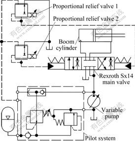
Fig.2 Schematic diagram of retrofitted electro-hydraulic system of excavator
still the LUDV system (Fig.3) of Rexroth[9] with good controllability. In Fig.3, y is the displacement of piston; Q1 and Q2 are the flows in and out to the cylinder, respectively; p1, p2, ps and pr are the pressures of head and rod sides of cylinder, system and return oil, respectively; A1 and A2 are the areas of piston in the head and rod sides of cylinder, respectively; xv is the displacement of spool; m is the equivalent mass of load.

Fig.3 Schematic diagram of LUDV hydraulic system after retrofitting
3 Model of electro-hydraulic proportional system
3.1 Dynamics of electro-hydraulic proportional valve
In this work, the electro-hydraulic proportional valve consists of proportional relief valves and SX-14 main valve. A transfer function from input current to the displacement of spool can be obtained as follows:
 (1)
(1)
where Xv is the Laplace transform of xv, m; KI is the current gain of electro-hydraulic proportional valves, m/A; b is the time constant of the first order system, s; Iv=I(t)-Id, I(t) and Id are respectively the control current of proportional valve and the current to overcome dead band, A.
3.2 Flow equation of electro-hydraulic proportional valve
In this work, LUDV system was adopted in the experimental robotic excavator. According to the theory of LUDV system[9], the flow equation can be gotten[10-11]:
 (2)
(2)
 (3)
(3)
where Δp is the spring-setting pressure of load sense valve, MPa; cd is the flow coefficient, m5/(N・s); w is the area gradient of orifice, m2/m; r is the oil density, kg/m3; Δp1 and Δp2 are the two orifices pressure, respectively, MPa. When the flow of excavator is not saturated, Δp is a nearly constant. In this work, the value was tested and gotten byexperiment.
In Fig.4, ps, pls and ?p represent the system pressure, the load sense valve pressure and the difference of pressure, respectively. The pressure experiment curves of the system show the variation of three kinds of pressures. Although ps and pls change with load, their difference does not change with load, the value approximates to 2.0 MPa. So, the effect of Δp on the flow across the valve can be neglected. It is assumed that the flow across the valve is proportional to the size of orifice valve, and the flow is not influenced by load. Then, Eqn.(2) can be simplified as
Q1=Kqxv(t), I(t)≥0 (4)
where Kq is the flow gain coefficient of valve, m2/s, and 

Fig.4 Curves of pressure experiment under boom moving condition
3.3 Continuity equation of hydraulic cylinder
Generally speaking, construction machine does not permit external leakage. At present, the external leakage can be controlled by sealing technology. On the other hand, it has been proven that the internal leakage of excavator is quite little by experiments. So, the influence of internal and external leakage of hydraulic system can be ignored. When the oil flows into head side of cylinder and discharges from rod side, the continuity equation[12-13] can be written as
 (5)
(5)
where V1 and V2 are the volumes of fluid flowing into and out the hydraulic cylinder, m3; βe is the effective bulk modulus (including liquid, air in oil and so on), N/m2.
3.4 Force equilibrium equation of hydraulic cylinder
It is assumed that the mass of oil in hydraulic cylinder is negligible, and the load is rigid[14-16]. Then the force equilibrium equation of hydraulic cylinder can be calculated from the Newton’s second law:
 (6)
(6)
where Bc is the viscous damping coefficient, N?s/m.
3.5 Simplified model of electro-hydraulic propor- tional system
After the Laplace transform of Eqns.(4)-(6), the simplified model can be expressed as
Y(s)=[b1Xv(s)+bfsFc(s)]/[s(a0s2+a1s+a2)] (7)
where Y(s) is the Laplace transform of y; b1=βeKq?  bf=V1V2; a0= V1V2m; a1=BcV1V2; a2=
4 Parameters estimation
From the process of modeling and Eqn.(7), it is clear that all parameters in the simplified model are related to the structure, the motional situation and the posture of excavator’s arm. Moreover, these parameters are time variable[13-16]. So it is quite difficult to get accurate values and mathematic equations of these parameters. To solve this problem, those important parameters of model were estimated approximately by the estimation equation and method proposed in this work.
4.1 Equivalent mass estimation for load on hydraulic cylinder
The load of boom hydraulic cylinder (it is assumed there is no external load) consists of boom, dipper and bucket. In Fig.1, boom, dipper and bucket rotate around points O1, O2 and O3, respectively. So their motions are not straight line motions about the cylinders, that is to say, their motion directions are different from y in Eqn.(5). So, m in Eqn.(6) cannot be simply regarded as the sum mass of boom, dipper and bucket.
Considering O1 at an axis of manipulator, the torque and angular acceleration can be given as follows:
 (8)
(8)
where M and w are the torque and angular acceleration of manipulator to O1, respectively;  is the length from point O1 to point B. According to the rotating law: M=Jω, we get
  that is
 (9)
(9)
where J is the equivalent moment inertia of manipulator to point O1, kg×m2, and it can be written as follows:
 (10)
(10)
J1, J2 and J3 are the moment inertia of boom, dipper and bucket to their own bary center respectively. The values of them can be obtained by dynamic simulation based on the dynamic model, J1= 450.9 N×m, J2 =240.2 N×m, J3= 94.9 N×m.
Comparing Eqn.(9) with Fc=mac, the equivalent mass at point B can be given:
 (11)
(11)
4.2 Estimation for load on hydraulic cylinder
The equivalent moment equation of manipulator to O1 is
 (12)
(12)
where 
 and
and  are the length from point O1 to point and
  respectively. Then, the counter force of load is
 (13)
(13)
4.3 Estimation for flow gain coefficient of valve
The flow of pump can be measured by flow transducer. The instrument used in this work was Multi-system 5050. The step response of flow of boom cylinder under the electro-hydraulic proportional valve controlled by the step current is shown in Fig.5. At the same time, the curve verifies Eqn.(1). Based on the experiment curve, the range of KqKI can be identified according to Eqns.(1) and (4). And then, according to data in Fig.4, we can get: KqKI=2.825×10⁻⁴ m3/(s・A).

Fig.5 Flow of boom cylinder under electro-hydraulic proportional value controlled by step current
5 Conclusions
1) The mathematic model of electro-hydraulic system is developed according to the characteristics of excavator. It is assumed that the flow across the valve is directly proportional to the size of valve orifice, and the influence of internal and external leakage of hydraulic system is ignored. The simplified model can be obtained: Y(s)= [b1Xv(s)+ bfsFc(s)]/[s(a0s2+a1s+a2)], where Y(s) and Xv(s) represent the displacement of piston and the displacement of spool.
2) From the model of electro-hydraulic system, we can obtain the equivalent mass  bearing force
  flow gain coefficient of value KqKI=2.825×10⁻⁴ m3/(s・A), where KI is the current gain of electro-hydraulic proportional valves.
References
[1] WANG Fei-yue, LEVEL P J A. On-line trajectory planning for autonomous robotic excavation based on force/torque sensor measurements [C]// The 1994 IEEE International Conference on Multisensory Fusion and Intelligent Systems. Piscatauny: IEEE, 1994: 371-378.
[2] HAGA M, HIROSHI W, FUJISHIMA K. Digging control system for hydraulic excavator [J]. Mechatronics, 2001, 11(6): 665-676.
[3] ZHANG Da-qing, HE Qing-hua, HAO Peng. Trajectory tracking control of hydraulic excavator bucket [J]. Journal of Jilin University: Engineering and Technology Edition, 2005, 35(5): 490-494. (in Chinese)
[4] LEE S U, CHANG P H. Control of a heavy-duty robotic excavator using time delay control with switching action with integral sliding surface [C]// The 2001 IEEE international Conference on Robotics & Automation. Seoul: IEEE, 2001: 3955-3960.
[5] PYUNG H C, LEE S J. A straight-line motion tracking control of hydraulic excavator system [J]. Mechatronics, 2002, 12(1): 119-138.
[6] LEE S U, CHANG H C. Control of a heavy-duty robotic excavator using time delay control with integral sliding surface [J]. Control Engineering Practice, 2002, 12(1): 697-711.
[7] NGUYEN H Q. Robust low level control of robotic excavation [D]. Sydney: University of Sydney, 2000: 8-11.
[8] SHAHRAM T, SEPTIMIU S E, KEYVAN H Z. Impedance control of a teleoperated excavator [J]. IEEE Transactions on Control Systems Technology, 2002, 10(3): 355-367.
[9] CHEN Qian-gen, JI Yun-feng, WU Wang-rong. Load independent flow distribution control system [J]. Hydraulic and Pneumatic, 2003(10): 9-11. (in Chinese)
[10] LI Hong-ren. Hydraulic controlling system [M]. Beijing: Defense Industry Press, 1981: 59-60. (in Chinese)
[11] BORA E. Improved nonlinear modeling and control of electro-hydraulic systems [D]. Boston: Northeastern University, 2000: 78-80.
[12] ZHANG Wei-han. The research of non-symmetry oil cylinder system controlled by symmetry valve and characteristic [D]. Changchun: Changchun University of Science and Technology, 2002: 55-56. (in Chinese)
[13] HE Qing-hua, LI Li-zheng, ZHOU Hong-bing. Modeling and parameter estimation for double triangle boom and its hydraulic system [J]. Journal of Central South University: Natural Science, 2001, 32(5): 519-522. (in Chinese)
[14] ZHANG Cheng-qian, ZHANG Guo-qiang. System identification and parameters estimation [M]. Beijing: China Machine Press, 1986: 101-103. (in Chinese)
[15] SHAHRAM T, PETER D L, SALCUDEAN S E. Identification of inertial and friction parameters for excavator arms [J]. IEEE Transactions on Robotics and Automation, 1999, 15(5): 966-971.
[16] BU Fan-ping, YAO Bin. Nonlinear adaptive robust control of hydraulic actuators regulated by proportional directional control valves with dead band and nonlinear flow gains [C]// Proceedings of the American Control Conference. Danvers: American Autom Control Council, 2000: 4129-4133.
(Edited by YANG Hua)
Foundation item: Project(2003AA430200) supported by the National High-Tech Research and Development Program of China
Received date: 2007-10-26; Accepted date: 2007-12-28
Corresponding author: HAO Peng, Doctoral candidate; Tel: +86-731-4020667; E-mail: hao_peng2000@163.com

