Improved control of intelligent excavator using proportional-integral-plus gain scheduling
来源期刊:中南大学学报(英文版)2012年第2期
论文作者:顾军 D. SEWARD
文章页码:384 - 392
Key words:robotic excavator; gain scheduling control; proportional-integral-plus; robustness
Abstract:
Consider the design and implementation of an electro-hydraulic control system for a robotic excavator, namely the Lancaster University computerized and intelligent excavator (LUCIE). The excavator was developed to autonomously dig trenches without human intervention. One stumbling block is the achievement of adequate, accurate, quick and smooth movement under automatic control, which is difficult for traditional control algorithm, e.g. PI/PID. A gain scheduling design, based on the true digital proportional-integral-plus (PIP) control methodology, was utilized to regulate the nonlinear joint dynamics. Simulation and initial field tests both demonstrated the feasibility and robustness of proposed technique to the uncertainties of parameters, time delay and load disturbances, with the excavator arm directed along specified trajectories in a smooth, fast and accurate manner. The tracking error magnitudes for oblique straight line and horizontal straight line are less than 20 mm and 50 mm, respectively, while the velocity reaches 9 m/min.
J. Cent. South Univ. (2012) 19: 384-392
DOI: 10.1007/s11771-012-1016-3![]()
GU Jun(顾军)1, D. SEWARD2
1. School of Mechanical and Electric Engineering, Soochow University, Suzhou 215006, China;
2. Engineering Department, Lancaster University, Lancaster, LA1 4YR, UK
? Central South University Press and Springer-Verlag Berlin Heidelberg 2012
Abstract: Consider the design and implementation of an electro-hydraulic control system for a robotic excavator, namely the Lancaster University computerized and intelligent excavator (LUCIE). The excavator was developed to autonomously dig trenches without human intervention. One stumbling block is the achievement of adequate, accurate, quick and smooth movement under automatic control, which is difficult for traditional control algorithm, e.g. PI/PID. A gain scheduling design, based on the true digital proportional-integral-plus (PIP) control methodology, was utilized to regulate the nonlinear joint dynamics. Simulation and initial field tests both demonstrated the feasibility and robustness of proposed technique to the uncertainties of parameters, time delay and load disturbances, with the excavator arm directed along specified trajectories in a smooth, fast and accurate manner. The tracking error magnitudes for oblique straight line and horizontal straight line are less than 20 mm and 50 mm, respectively, while the velocity reaches 9 m/min.
Key words: robotic excavator; gain scheduling control; proportional-integral-plus; robustness
1 Introduction
In the civil and construction industries, a large number of manually controlled plants are currently deployed for a wide variety of tasks within the construction process. The excavation of foundations, general earthworks and earth removal tasks are activities which involve the machine operator in a series of repetitive operations. Full or partial automation may improve excavation productivity, efficiency and operator safety, especially in applications such as underground mining or the removal of hazardous waste.
The Engineering Department of Lancaster University has a long record of research on autonomous excavation. In particular, the Lancaster University computerized intelligent excavator (LUCIE) is based on a commercial manual hydraulic excavator, but with an on-board computer system in place of a driver to control the hydraulics and therefore the machine [1-3].
In this work, an intelligent excavator was developed that could autonomously dig a trench in virgin ground without human intervention. Smooth, fast and accurate control of the excavator joints is an essential component of the system. In this regard, the present work applies the proportional-integral-plus (PIP) methodology to the joint control problem. Such PIP controllers are based on true digital control (TDC) design philosophy, in which the design of control systems is carried out overtly in discrete time [4-7]. Non-minimal state space (NMSS) models [8-9] are formulated so that full state variable feedback control can be implemented directly from the measured input and output signals of the controlled process, without resorting to the design of a deterministic state reconstructor or a stochastic Kalman filter.
Over the last few years, such NMSS/PIP control systems have been successfully employed in a range of practical examples, including piling rig positioning [10], automated verticality alignment system for a vibro-lance [11] and LUCIE [3, 12]. However, in the latter case, the nonlinear joint dynamics can sometimes yield an oscillatory response for bucket position. In order to maintain smooth control, therefore, previous control algorithms typically utilized a relatively slow control action.
2 Theory of proposed approach
2.1 NMSS/PIP control
Although there are some interactions between the dipper and boom hydraulics, the implementation results considered below suggest that a fully multivariable control approach is not required in practice. For this reason, this work was based on the simplest multiple loop, single input, single output control algorithms, i.e. PIP controllers were designed for each joint separately.
In order to develop a linear PIP algorithm, a linearized representation of the system is first required. In this regard, the small perturbation behavior of each joint was approximated by the following discrete-time transfer function:
![]() (1)
(1)
where yk is the joint angle (degree); uk is the applied voltage, expressed as a percentage in the range from -1 000 to +1 000 V. Positive and negative inputs open or close the joint respectively. Here, A(z-1) and B(z-1) are appropriately defined polynomials in the backward shift operator.
For convenience, any pure time delay of δ (δ>1) samples can be accounted for by setting the δ-1 leading parameters of the B(z-1) polynomial to zero.
This work utilizes the simplified refined instrumental variable (SRIV) algorithm to estimate the model parameters [6, 13]. The model structure first need to be identified, i.e. the most appropriate values for the triad [n, m, δ]. Two main statistical measures employed to help determine these values are the coefficient of determination ![]() based on the response error; and young’s information criterion (YIC), which provides a combined measure of model fit and parametric efficiency [6, 13].
based on the response error; and young’s information criterion (YIC), which provides a combined measure of model fit and parametric efficiency [6, 13].
These statistical tools and associated estimation algorithms have been assembled as the Captain toolbox within the Matlab software environment [14].
It is easy to show that Eq. (1) can be represented by the following linear non-minimal state space NMSS equation:
![]() (2)
(2)
where F, g, d and h are defined as [4-6]
F=
 (3)
(3)
![]() (4)
(4)
![]() (5)
(5)
![]() (6)
(6)
The (n+m) dimensional non-minimal state vector xk consists of the present and past sampled values of the input and output variables, i.e.,
![]() (7)
(7)
where zk=zk-1+(yd,k-yk) is the integral-of-error between the reference or command input yd,k and the sampled output yk. Inherent type 1 servo-mechanism performance is introduced by means of the integral-of-error state zk. If the closed-loop system is stable, then this ensures that steady-state tracking of the command is inherent in the design.
The control law associated with the NMSS Eq. (2) takes the usual state variable feedback (SVF) form:
uk=-kTxk (8)
where ![]() is the SVF control gain vector. In more conventional block-diagram terms, the SVF controller (Eq. (8)) can be implemented, as shown in Fig. 1.
is the SVF control gain vector. In more conventional block-diagram terms, the SVF controller (Eq. (8)) can be implemented, as shown in Fig. 1.

Fig. 1 PIP control in feedback form
It is clear from Fig. 1 that PIP control can be considered as one particular extension of the ubiquitous PI controller, where the PI action is, in general, enhanced by the higher order forward path and feedback compensators 1/G(z-1) and F(z-1):
![]() (9)
(9)
However, because it fully exploits the power of SVF within the NMSS setting, PIP control is inherently much more flexible and sophisticated, allowing for well-known SVF strategies such as closed-loop pole assignment, with decoupling control in the multivariable case; or optimization in terms of a conventional linear- quadratic (LQ) cost function, determined by the steady state solution of the ubiquitous discrete-time matrix Riccati equation. One of the main advantages of the PIP controller lies in its inherent state-space formation, which guarantees closed-loop stability and allows both for pole assignment and optimal LQ control [5].
Note that, in the NMSS/PIP case, the elements of the LQ weighting matrices have particularly simple interpretation, since the diagonal elements directly define weights assigned to the measured input and output variables.
2.2 Gain scheduling control
Gain scheduling is a powerful approach for the control of nonlinear and time-varying systems because of its simplicity and ability to use linear design methods [15]. The design of a gain scheduling controller involves the following steps [16]:
1) Linearize the plant about a finite number of representative operating points;
2) Design linear controllers for plant linearizations at each operating point;
3) Interpolate the parameters of various linear controllers to achieve adequate performance of linearized closed-loop system at all points where the plant is expected to operate so that the resulting family of linear controllers is the gain scheduling controller;
4) Implement the gain scheduling controller on the nonlinear plant.
The parameters of the gain scheduling controller evolve as functions of the plant states, inputs, outputs and exogenous parameters or some combination of these. The gain-scheduled controller takes the general form, as shown in Fig. 2. However, for this particular implementation, interpolation between different operating points does not appear necessarily. The inherent robustness of the basic PIP design over a range of operating levels ensures that the simple approach discussed below (based on two models for each joint) works very well in practice. This also has the advantage that the final design is particularly straightforward to implement.
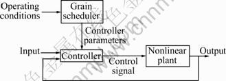
Fig. 2 Gain-scheduled controller
3 Excavator control
The tracked excavator used as the platform for the LUCIE project is a JCB 801 mini excavator, as shown in Fig. 3. The machine has an operating mass of 1.4 t, a width less than 1 m, a bucket capacity of approximately 9 200 N and a maximum vertical digging depth of about 1.5 m. All of the arm movements are hydraulically driven. It had been refitted with electro-hydraulic servo valves, associated sensors and a computer control system, to allow for the development, experimental evaluation and refinement of the new intelligent control systems. References [1-2, 12, 17] described the details about LUCIE system architecture including hardware and software.

Fig. 3 LUCIE platform: JCB 801 mini excavator
During automatic digging, the most important sub-target was to keep the bucket moving along a specified path quickly, smoothly and accurately. The straight line was the most common path employed, as in the case of dragging a flat bottomed trench in the ground, or moving the earth from the digging point to the dumping point.
Numerous researchers had considered this problem with various degrees of success. For example, NGUYEN et al [18] applied feedback linearization methods. In this case, experimental results indicate that the performance could be degraded by the presence of noise. Fuzzy moving sliding mode [19] and impedance controllers [20] had similarly been developed for robot excavators.
BUDNY et al [21] considered the control of an excavator bucket in straight lines by applying Danfoss PVG32 load-independent hydraulic valves. Here, the bucket was moved along planar vertical and horizontal lines in both free space and in a soil box filled with homogenous mildly humid sand. Although the accuracy was kept within 10 cm, the velocity achieved was relatively low, only about 2 m/min.
Similar tests for LUCIE, utilizing conventional PI methods [1], also required slow movement of the bucket in order to maintain accurate control. This was the motivation for the development of a fixed-gain PIP algorithm for regulating the joint dynamics [3, 12]. The following section was built on this earlier research, by developing a scheduled-gain PIP control system for LUCIE and implementing further field tests.
3.1 Control design for LUCIE
In order to identify the dominant dynamics of the excavator, joint data were collected for typical step changes in the applied voltage. In this case, the simplified refined instrumental variable (SRIV) algorithm [2], combined with the YIC and ![]() identification criteria, suggested that a first order transfer function model with either one or two samples time delay provided the best explanation of data across a wide range of operating conditions [3].
identification criteria, suggested that a first order transfer function model with either one or two samples time delay provided the best explanation of data across a wide range of operating conditions [3].
Furthermore, in common with many other hydraulic systems, such as system illustrated in Ref. [10], it is clear that both the boom and dipper angles behave as integrators, with an almost constant rate of change for a given input signal. For simplicity in the initial study, therefore, the following model structure was employed [22]:
![]() (10)
(10)
where y(k) represents the boom or dipper joint angle; u(k) is the associated input voltage; the time varying numerator b(u) is estimated using SRIV methods. A sampling rate of 0.1 s was utilized throughout, since it was within the capabilities of the on-line computer and was found to work well in practice.
Note that for all the analyses in the present work, the dead-zone was removed at the data collection stage, so that a positive voltage scale from 0 to 1 000 V caused the boom to open, whilst a negative voltage up to -1 000 V reverse the direction. In this manner, the boom could be positioned at an angle between 0° and 60°, where the later figure represents fully open. Similarly, a scaled input voltage to the dipper in the range from -1 000 to 1 000 V causes the dipper angle to vary from -30° (fully open) to -140°.
For example, a boom opening experiment with an input voltage of 60 V yielded Eq. (10) with b=0.005. In this case, specifying closed-loop poles at 0.6 on the real axis of the complex z-plane, yielded robust PIP control of the boom angle when the latter followed an opening trajectory. The PIP control gain vector was defined as
![]() (11)
(11)
By contrast, the PIP control algorithm for a decreasing boom angle, was based on a boom closing experiment with an input voltage of -40 V, which yielded b=0.018 and
![]() (12)
(12)
A similar approach was taken for the dipper angle. With an input voltage of -100 and 100 V to open or close the joint, b=-0.012 and b=-0.018, respectively. The associated PIP gain vectors were given by
![]() (13)
(13)
and
![]() (14)
(14)
The above feedback gains (Eqs. (11)-(14)) were utilized in the design of a scheduled control algorithm.
Here, the key decision is how to choose appropriate control gains for each sampling period. In this regard, the controller utilized a comparison between the current measured joint angle and the expected (or commanded) angle of arm at each sampling instant. For example, if the angle was larger than its expected value, the scheduler would choose the control parameters for joint closing case.
3.2 Simulation
To demonstrate the behavior of proposed control scheme, this work considered the simulation response shown in the polar coordinate plot of Fig. 4. The simulation was based on a combination of excavator kinematics and data-based nonlinear dynamic models, implemented using the Matlab/Simulink package, as described by Ref. [3].
The objective of this simulation was to move the bucket from its initial position (1 378, 109) to (2 000, -600), and then to (1 000, -600), where the (x, y) coordinates were given in millimeter from the point of attachment of the boom to the vehicle.
To avoid discontinuous force variations that may cause the arms to jerk during operation, the acceleration of arms should be continuous. In this regard, the trajectory between each set of coordinates took the form of the fifth order polynomial jerk-free straight line as suggested by Ref. [23]. The objective was to complete the whole motion within 5 s, including a wait of 0.3 s at the initial position.
To achieve this aim, appropriate time varying (x, y) coordinates were first calculated off-line. These were shown as the dashed lines on the lower two plots of Fig. 4(a). The joint angle set points were calculated on-line, shown as dashed traces in the middle two plots of Fig. 4(a). The PIP-gain scheduling control algorithms were used to adjust the input drive-demand (top two graphs) in order to meet these targets. It is clear from Fig. 4(b) that the bucket was moved along the defined straight-line trajectories (dashed line) well within the required accuracy (solid trace) and within the demanded time limitation. The excellent control performance of the simulation demonstrates that the idea of using the state of current sample time to schedule the current control parameters is a good choice.
Although it is not shown in Fig. 4, PIP-gain scheduling algorithms provided considerably improved performance over a PID controller obtained using the Ziegler-Nichols ultimate sensitivity method [3]. As discussed in Ref. [3], the latter algorithm only provided accurate control for relatively slow movements of the bucket.

Fig. 4 Simulation of bucket position movement in desired straight lines utilizing PIP-gain scheduling controller: (a) Time response; (b) Polar coordinate plot
3.3 Field experiments
The test illustrated here was designed to move the bucket along a desired oblique straight line and a horizontal straight line. For safety reasons, all the bucket movements for these preliminary field tests were in air only. A Turbo C++ program was executed under the DOS 6.0 operating system, to realize the PIP-gain scheduling control algorithm. During the experiment, the hydraulic pressure was kept at 1.1×10⁷ Pa.
Figure 5(a) shows the bucket moving from its initial position at (1 368, 829) to (1 600, 1 320) along an oblique straight line in 4 s. Following a programmed 1 s delay, the bucket moved to (2 200, 1 320) along a horizontal straight line in a further 4 s. The (x, y) coordinates were given in millimeter from the reference point as before.
As expected, the bucket moved closely along the reference path with an error magnitude less than 20 mm during the oblique straight line motion. When the bucket moved along the horizontal straight line, the error magnitude was maintained lower than 50 mm. The velocity reached 9 m/min during the whole tracking operation. Compared with the performance of fixed-gain PIP controller which was developed in Ref. [12], the tracking accuracies of oblique straight line and horizontal straight line were at least 10 mm better and 30 mm better, respectively.

Fig. 5 Implementation results of desired trajectory, simulation response and LUCIE experimental data: (a) Bucket tracking; (b) Boom angle tracking; (c) Dipper angle tracking
Since the bucket position was decided by the angle of boom and dipper according to the kinematic relationship of joints established by Ref. [2], the key to the proposed bucket position control depended on the respective boom and dipper angle controllers. In this regard, Figs. 5(b) and (c) show the tracking responses of the boom and dipper, respectively. In these figures, the actual angles of boom and dipper closely followed the equivalent simulated values, attesting to the accuracy of the previously developed nonlinear simulation model [3], as well as the associated linear transfer functions for control system design.
However, it was clear from Fig. 5(b) that there were some vibrations when the boom tracked the desired angle. Although this vibration was less than 1.5°, it yielded a noticeable positional error in bucket position because of the long transmission length of over 1.5 m. This was the main factor that led to bucket position errors. Most commonly, such vibration occurred when: 1) the boom changed its direction of motion, e.g. from opening to closing; 2) any movement from stationary; or 3) big changes of drive-demand even if they were in the same direction.
Another factor that could partially explain the position errors was delayed responses from the hydraulic system, i.e. the response time of hydraulic system sometimes lagged behind the real time requirements. In particular, longer pure time delays than the unity implied by Eq. (10) sometimes occurred.
For this reason, controllers based on models with longer time delays were considered. In fact, one of the key advantages of PIP control over conventional PI/PID design is that the former approach robustly accommodates such long pure time delays [3-4].
4 Robustness of PIP-gain scheduling controller
Since the hydraulic system was nonlinear, it was impossible to expect the linear model to describe all the dynamic behaviors of the system. Many uncertainties in the operation affected the performance, e.g. unmodelled dynamics and time delay mismatch. The strategy was that the controller should overcome strong nonlinearity and significant uncertainty. Here, the robustness of the PIP-gain scheduling controller was discussed in more detail by means of simulation.
4.1 Robustness to parametric uncertainty
An important practical consideration in model based control system design is the robustness of the control system performance to uncertainty associated with the model parameters. In general, PIP control is relatively robust against realistic modelling uncertainties [24].
In the bucket position controller, the transfer function models used to describe the system dynamics were in the form of Eq. (1). The numerator B(z-1) was different corresponding to different drive-demands in the opening and closing case, respectively. For simplicity, the coefficients of A(z-1) were assumed to be (1-z-1) for any drive-demand. In theory, a set of control parameters should be provided corresponding to different numerators to ensure that the closed-loop response was stable. Actually, only two sets of parameters, Eqs. (11) and (12), were utilized to cope with the boom opening and closing cases, respectively. And similarly, two sets of parameters, Eqs. (13) and (14), were utilized to cope with the dipper opening and closing cases, respectively. The good performance of simulations and real machine experiments all demonstrate the robustness of the approach to uncertainty in B(z-1) and A(z-1).
Additionally, it should be noted that although the PIP control form had a strong ability to remain robust against parameters uncertainty, the larger motion inertia caused by sudden quick movements may change the structure of the transfer function utilized to describe the system dynamics. This could severely degrade the control performance.
4.2 Robustness to time delay uncertainty
One assumption discussed above was that the model parameters were subjected to uncertainty but the transfer function model structure (i.e., the order of model numerator polynomial, the order of model denominator polynomial and time delay) remained constant in all the realizations. In the analysis above, for example, the unity time delay was assumed for the boom transfer function models. In fact, the responses of boom to some drive- demands were not exactly one time delay. For example when the drive-demands changed from positive to negative or in the opening case, the response appeared was slower than one time delay. It was interesting to examine the situation where this assumption was relaxed to allow for uncertainty in the time delay.
The PIP controller automatically handled pure time delays when it was short in comparison with the dominant time constant of the system by simply feeding back sufficient past values of the input variable to span the time delay in NMSS form. In particular, the result in Fig. 6 was based on single simulation using the boom system with the control design based on the original one sample time delay, but with the simulated delay changed to two samples for the boom opening models. It was clear that the boom tracking response of two time delay model was almost as good as the response of unity delay model. In this example, the oscillations that degraded the tracking performance only existed when the delay was increased to three samples, as shown in Fig. 6.
4.3 Robustness to load disturbances
In practice, the bucket position control system was subjected to a number of load disturbances, especially when the excavator was digging in the earth. Here, the closed-loop computer simulation was used to study the performance of the controllers in relation to such load disturbances.

Fig. 6 Tracking responses of boom PIP-gain scheduling control with time delay mismatch
In simulation, the disturbances added to the boom and dipper are shown in Figs. 7(a) and (b). The result showed that the bucket trace was not as smooth as that of Fig. 4, since there were jumps in the joint angles occurring when the magnitude of the disturbances were changed, as shown in Figs. 7(a) and (b) (e.g. at 7.1 s, 8.1 s, 9.1 s and 10.1 s). The performance shown in Fig. 7(c) indicated that with the load disturbances, the bucket still kept moving along the defined straight-lines within the required accuracy (less than 50 mm). Although overshoots appeared, the magnitude was limited and the output settled down to the command level quickly.
The results could be explained straightforwardly by considering the closed-loop transfer function without model mismatch for the standard structure:
![]()
![]()
![]() (15)
(15)
The transfer function took the usual form, where the overall response of the system could be divided into two components: the standard closed-loop response to the command input, yd(k) and the response to the load disturbance, v(k).
It is clear that the F(z-1)B(z-1) component was the approximate negative of the G(z-1)A(z-1) term [19], and normally, kiB(z-1) was much larger than G(z-1)A(z-1)・ (1-z-1). So, if the load disturbances were not very severe, the latter part of Eq.(15) rejected the effects of the load disturbance (i.e., the output variable returned to the desired level).
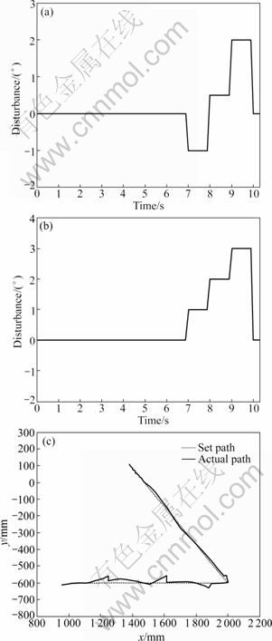
Fig. 7 Simulation results of bucket position PIP-gain scheduling control moving in straight lines with load disturbances: (a) Disturbances applied to boom; (b) Disturbances applied to dipper; (b) Simulation result
5 Conclusions
1) This work follows up earlier research into PIP control of the LUCIE by developing a gain scheduling system. Appropriate PIP control gains are chosen at each sampling instant, based on the current operating state of the excavator arm.
2) Unmodelled dynamic effects such as vibrations of the boom, together with occasional large time delays, both influence the tracking performance of the bucket position controller. Nonetheless, the results obtained in both simulation and preliminary field tests are promising. The PIP control structure inherently avoids problems such as integral windup and provides good robustness against parametric uncertainties, short time delay mismatch, and outside disturbances. Gain scheduling is a simple but powerful technique used to deal with the problem of controlling the nonlinear and time-varying system. Combining the principles of gain-scheduling control with PIP design methods helps to achieve good robustness and performance for this application.
3) In particular, the bucket positional accuracy is within 50 mm, while the velocity reaches 9 m/min, which are within the requirements of normal excavation tasks. In fact, the new control system offers performance that is comparable to that achieved by an average human operator. The control techniques developed here can also be developed for other difficult nonlinear systems.
References
[1] SEWARD D W, QUAYLE S. LUCIE―Lancaster University computerised intelligent excavator [J]. Circuit Cellar: Computer Applications, 1997, 79: 67-73.
[2] BRADLEY D A, SEWARD D W. The development, control and operation of an autonomous robotic excavator [J]. Journal of Intelligent and Robotic Systems, 1998, 21(1): 73-97.
[3] GU J, TAYLOR C J, SEWARD D. Proportional-integral-plus control of an intelligent excavator [J]. Journal of Computer-Aided Civil and Infrastructure Engineering, 2004, 19(1): 16-27.
[4] YOUNG P C, BEHZADI M A, WANG C L,CHOTAI A. Direct digital and adaptive control by input-output, state variable feedback pole assignment [J]. International Journal of Control, 1987, 46(6): 1861-1881.
[5] Taylor C J, Chotai A, Young P C. State space control system design based on non-minimal state-variable feedback: Further generalisation and unification results [J]. International Journal of Control, 2000, 73(14): 1329-1345.
[6] Young P C. Simplified refined instrumental variable (SRIV) estimation and true digital control (TDC): A tutorial introduction[C]// Proceedings of the First European Control Conference. Grenoble, 1991: 1295-1306.
[7] TAYLOR C J, CHOTAI A, YOUNG P C. Nonlinear control by input-output state variable feedback pole assignment [J]. International Journal of Control, 2009, 82(6): 1029-1044.
[8] EXADAKTYLOS V, TAYLOR C J, WANG L, YOUNG P C. Forward path model predictive control using a non-minimal state space form [C]// Proceedings Journal of Systems and Control. IMECHE, 2009, 223(3): 353-369.
[9] WANG L, GAWTHROP P, YOUNG P C, TAYLOR C J. Non-minimal state space model-based continuous-time model predictive control with constraints [J]. International Journal of Control, 2009, 82(6): 1122-1137.
[10] SHABAN E M, AKO S, TAYLOR C J, SEWARD D W. Development of an automated verticality alignment system for a vibro-lance [J]. Automation in Construction, 2008, 17(5): 645-655.
[11] DIXON R, CHOTAI A, YOUNG P C, SCOTT J N. The automation of piling rig positioning utilising multivariable proportional-integral- plus (PIP) control [C]// Processing of 12th International Conference on Systems Engineering, ICSE’97. Coventry University, UK, 1997: 9-11.
[12] GU J, SEWARD D. Digital servo control of a robotic excavator [J]. Chinese Journal of Mechanical Engineering, 2009, 22(2): 190-197.
[13] YOUNG P C. Recursive estimation and time series analysis (communication and control engineering series) [M]. Berlin: Springer-Verlag, 1984.
[14] TAYLOR C J, PEDREGAL D J, YOUNG P C, TYCH W. Environmental time series analysis and forecasting with the captain toolbox [J]. Environmental Modelling and Software, 2007, 22(6): 797-814.
[15] MURRAY-SMITH R, JOHANSEN T A. Multiple model approaches to modelling and control [M]. Oxford: Taylor and Francis, 1997.
[16] KAMINER K, PASCOAL A M, KHARGONEKAR P P, COLEMAN E E. A velocity algorithm for the implementation of gain-scheduled controllers [J]. Automatica, 1995, 31(8): 1185-1191.
[17] Seward D W, Pace C, Agate R. Safe and effective navigation of autonomous robots in hazardous environments [J]. Autonomous Robots, 2007, 22(3): 223-242.
[18] NGUYEN Q, HA Q, RYE D, DURRANT-WHYTE H. Feedback linearization control of electro hydraulic systems of a robotic excavator [C]// Processing of Australian Conference on Robotics and Automation. Brisbane, 1999: 190-195.
[19] HA Q, RYE D, DURRANT-WHYTE H. Fuzzy moving sliding mode control with application to robotic manipulators [J]. Automatica, 1999, 35(4): 607-616.
[20] Ha Q, Nguyen Q, Rye D, DURRANT-WHYTE H. Impedance control of a hydraulic actuated robotic excavator [J]. Journal of Automation in Construction, 2000, 9(5/6): 421-435.
[21] BUDNY E, CHLOSTA M, GUTKOWSKI W. Load-independent control of a hydraulic excavator [J]. Journal of Automation in Construction, 2003, 12(3): 245-254.
[22] Gu J, Taylor C J, Seward D. Modelling of an hydraulic excavator using simplified refined instrumental variable (SRIV) algorithm [J]. Journal of Control Theory and Applications, 2007, 5(4): 391-396.
[23] Chiang M H, Murrenhoff H. Adaptive servo-control for hydraulic excavators [C]// Power Transmission and Motion Control [PTMC’98]. UK: Professional Engineering Publishing Limited London and Bury St Edmunds, 1998: 81-95.
[24] Taylor C J. Generalized proportional-integral-plus (PIP) control [D]. Lancaster: Lancaster University, 1996.
(Edited by DENG Lü-xiang)
Foundation item: Project(K5117827) supported by Scientific Research Foundation for the Returned Overseas Chinese Scholars; Project(08KJB510021) supported by the Natural Science Research Council of Jiangsu Province, China; Project(Q3117918) supported by Scientific Research Foundation for Young Teachers of Soochow University, China; Project(60910001) supported by National Natural Science Foundation of China
Received date: 2011-01-07; Accepted date: 2011-03-29
Corresponding author: GU Jun, Associate Professor, PhD; Tel: +86-512-67165607; E-mail: gujun@suda.edu.cn

