J. Cent. South Univ. (2017) 24: 2010-2018
DOI: https://doi.org/10.1007/s11771-017-3610-x

Development of dynamic-mathematical model of hydraulic excavator
Vujic Dragoljub1, Lazarevic Olgica2, Batinic Vojislav2
1. Military Technical Institute, Belgrade 11000, Serbia;
2. Military Academy, Belgrade 11000, Serbia
 Central South University Press and Springer-Verlag GmbH Germany 2017
Abstract: This work deals with analysis of dynamic behaviour of hydraulic excavator on the basis of developed dynamic-mathematical model. The mathematical model with maximum five degrees of freedom is extended by new generalized coordinate which represents rotation around transversal main central axis of inertia of undercarriage. The excavator is described by a system of six nonlinear, nonhomogenous differential equations of the second kind. Numerical analysis of the differential equations has been done for BTH-600 hydraulic excavator with moving mechanism with pneumatic wheels.
Key words: hydraulic excavator; dynamic behaviour; dynamic-mathematical model
1 Introduction
Hydraulic excavators are the machines intended for terrain excavation, with cyclic operating in different terrain conditions. Possible mistakes or omissions in design, manufacture and exploitation may be the cause for the great number of unwanted consequences, such as failure, influence on environment, influence on operator. Construction and nature of operating process of hydraulic excavators may generate considerable vibrations which reflect in additional dynamic loads of excavator. That is why an adequate dynamic- mathematical model is necessary prerequisite for testing dynamic load and forces in joints of excavator��s construction parts. Also, using the mathematical model in the design phase, would reduce expenses of testing in real conditions. Available literature offers different approaches to modeling dynamics of hydraulic excavators, which are most often different by purpose, the way of performing and number of degrees of freedom.
The first group of research dynamic behaviour of excavator is oriented to the design of excavator model for the purpose of testing its stability, because the stability of excavator��s operating is one of its most important parameters. International standards prescribe the requirements for determining coefficient of excavator��s static stability and coefficient of hydraulic stability of excavator��s driving mechanisms [1]. The defined coefficients of stability are placed as limitations already at synthesis of kinematic chain and driving mechanism of excavator. It is known that the static stability does not always provide dynamic stability of the system. So, it is necessary to analyze stability of balance position by causing disturbance of the system. Besides, during the time, displacements (generalized coordinates) of the system are followed, do they decline, do they grow or remain at allowed limits. In Ref. [2], a dynamic behaviour of excavator by using linear model with five degrees of freedom is analyzed, where equations in the model are with constant coefficients, with applying the Langrange equations of the second kind. The same principle was used in Ref. [3] for analysis of dynamics and kinematics of hydraulic excavator with three degrees of freedom, from the aspect of following the manipulator��s motion. In Ref. [4], a dynamic behaviour of hydraulic excavator with three degrees of freedom that refers to manipulator is analyzed. The problem, like in Refs. [5, 6], has been solved by applying the Newton- Euler methods. In Ref. [7], dynamics of behaviour of mechanism for lifting the load is analyzed, where it has been shown that for vertical load lifting it is necessary to provide adequate conditions for regular dynamic analysis while in the design phase.
The second group of models refers to examining dynamic loads and vibrations of the system. In Ref. [8], an ambient simulation of excavator��s operating is shown, by which a dynamics of operating is explained including dynamics of hydraulic and mechanical system. In Ref. [9], a strenght of hydraulic excavator's cabin is analyzed under the impact of dynamic loads. Durability of the cabins is estimated by durability tests with the help of exciting vibrations. In Ref. [10], absorbing the vibrations is analysed with the help of acceleration and changing feedback.
The control of hydraulic excavator manipulator��s operating is analyzed and effective and reliable way for control of excavator automated systems is proposed [11]. A model of numerical analysis of excavator��s vibrations is presented [12]. Dynamics of mechanism for cutting with polymer sheets is analyzed [13]. Hydraulic excavators equipped with hybrid systems are considered with the aim of saving energy and reducing environment pollution by exhaust gases [14]. For modeling and simulation of dynamic parameters, a package Autodesk Inventov is used as well as its dynamic simulator [15]. A 3D model of excavator��s operating equipment is developed and is used for research of geometry, forces, kinematic and dynamic parameters of mechanical system.
The third group of papers, which refers to testing the effect of hydraulic excavator's vibrations to human body, basically does not represent a new approach, but because of its significance a considerable part of scientific audience studies this problem as an independent one. A vibration influence to human body is tested [16]. KIM et al [17] analyzed dynamic modeling of the operator��s seat, in the excavators, on the basis of measuring inertia matrix when centre of the body moves forward and back or moves in vertical direction. Results of the research [18] reveal the connection between change of modal parameters and dynamic characteristics of the structure and set the foundations for improving the general quality of mechanical products.
By the analysis of available literature it is established that the dynamics of the behaviour of hydraulic excavator is analyzed with maximum five degrees of freedom [2]. However, taking in mind functioning of excavator it would be natural for the model space to expand for one more degree of freedom, i.e. rotating around transversal main central axis of inerta of undercarriage, which is one of the aims of this paper. By this, a model is enriched for one more generalized coordinate, by which an excavator's behaviour regarding transversal axis of the system is followed. The developed model enables testing changes of generalized coordinates.
The rest of this work is organized in the following way: after the introduction a physical excavator model is described, the coordinate systems are established and the model space as well as kinetic and potential energy is described. Then, equations of system motion are set and solved and simulation results are analyzed on a computer. In the end, a conclusion is made.
2 Dynamic model of excavator
In the analysis of the dynamic stability of the excavator, we observe a physical model (Fig. 1) of the general configuration consisting of: undercarriage (1), rotary link (2), boom (3), arm (4) and bucket (5). The links of kinematic pairs are connected, indirectly or directly, by hydraulic actuators: hydromotor driving rotation platform (S2) and hydraulic cylinders driving manipulator (S3, S4, S5).

Fig. 1 Physical model of hydraulic excavator:(1-Undercarriage (pneumatics); 2-Rotary link (platform); 3-Boom; 4-Arm (stick); 5-Bucket)
For the shown physical excavator model, a dynamic model (Fig. 2) is presented, with the following assumptions:
1) Dynamic model of excavator is nonconservative system with stationary and ideal connections;
2) Small oscillations of the system around the position of the stable balance are observed;
3) Foundation supporting the excavator has elastic- damped features;
4) The links of kinematic chain of excavator are rigid bodies;
5) Hydraulic actuators of driving mechanisms are elastic-dampering elements.

Fig. 2 Dynamic model of hydraulic excavator:
2.1 Model space
The motion of the excavator (Fig. 2) is defined by generalized coordinates q:
 (1)
(1)
where zc is vertical displacement of the mass centre of undercarriage; �� is the angle of rotation around longitudinal main central axis of inertia O1x1 of undercarriage; �� is the angle of rotation around transversal main central axis of inertia O1y1 of undercarriage; �� is the angle of manipulator boom rotation around the axis O3y3 of the joint to which rotary link is attached; �� is the angle of manipulator arm rotation around the axis O4y4 of the joint in the end of the boom and �� is the angle of manipulator bucket rotation around the axis O5y5 of the joint in the end of the arm.
It is supposed that generalized coordinates are of small size measured from the position of the stable balance of the system. The critical positions of the excavator are analyzed when the plane of the manipulator is normal to longitudinal plane of undercarriage (Fig. 2).
2.2 Coordinate systems
The position of the excavator is defined in regard to stationary (absolute) coordinate system Oxyz. The coordinate beginning O of the absolute system is in the mass centre of undercarriage for the whole system (undercarriage, rotary link, boom, arm and bucket). The axis Ox is directed at direction of longitudinal axis, and the axis Oy is directed at direction of transversal main central axis of inertia in a position of static balance of the whole system and axis Oz is directed vertically downward.
For determining the position of links of kinematic chain, excavator local coordinate systems (Fig. 2) are established.
1) O1x1y1z1 is the moving coordinate system adopted for the mass centre O1 of undercarriage. The axis Ox1 coincides with longitudinal axis, and the axis Oy1 with transversal main central axis of inertia of undercarriage in balance position and the axis Oz1 is directed vertically downward.
2) O2x2y2z2 is the moving coordinate system connected to the center of axial bearing O2;
3) O3x3y3z3 is the coordinate system connected to center of the joint O3 and rotated for the generalized coordinate �� in regard to coordinate system O3x3y3z3;
4) O4x4y4z4 is the coordinate system connected to the center of joint O4 and rotated for the generalized coordinate �� in regard to coordinate system O3x3y3z3;
5) O5x5y5z5 is the coordinate system connected to the center of joint O5 and rotated for generalized coordinate �� in regard to coordinate system O4x4y4z4.
2.3 Kinetic energy of system
Kinetic energy of the system is equal to total of kinetic energies of the system segments:
 (2)
(2)
where Ek1 is the kinetic energy of undercarriage; Ek2 is the kinetic energy of platform; Ek3 is the kinetic energy of boom; Ek4 is the kinetic energy of arm-stick and Ek5 is the kinetic energy of bucket.
Further,
 (3)
(3)
 (4)
(4)
 (5)
(5)
 (6)
(6)
 (7)
(7)


 (8)
(8)
where mi (i=1, 2, 3, 4, 5) is mass of particular parts of excavator: undercarriage, platform, boom, arm and bucket; vi (i=1, P, S, R, K) is absolute velocity of the mass centre of particular parts of the excavator: undercarriage, platform, boom, arm and bucket; Jjxk (j, k=1, 2, 3, 4, 5) is main central axial moment of mass inertia of particular parts of the excavator for longitudinal axis Ojxk which passes through the mass centre Oj; J1y1 is main central axial moment of mass inertia of undercarriage for transversal axis O1y1 which passes through the mass centre O1; J2y2 is main central axial moment of mass inertia of rotary link for transversal axis O2y2 which passes through the mass centre O2; 
 are anglular velocities of undercarriage around its longitudinal O1x1 and transversal O1y1 axis of inertia, respectively;
  are anglular velocities of the boom, arm and bucket of the excavator around their longitudinal O3y3, O4y4 and O5y5 axes of inertia, respectively.
2.4 Potential energy of system
For the actuating the civil engineering machines the moving mechanisms with caterpillars and wheels are used. In this work, a hydraulic excavator with moving mechanism with pneumatic wheels is analyzed. Features of the moving mechanism with pneumatic wheels are small rolling resistance, great moving speeds, on the solid and public roads.
The mentioned characteristics of the moving mechanism with pneumatic wheels make excavators with these mechanisms quite appropriate while performing various civil works. One of the disadvantages of these mechanisms is relatively small allowed load of the wheels with pneumatics. By building in the mechanisms with stabilizer blades in undercarriage this disadvantage may be removed. Schematic preview of the supporting contour and configuration of stabilizer blades of the considered excavator is given in Fig. 3.
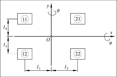
Fig. 3 Supporting contour and configuration of stabilizer blades
Potential energy of the adopted dynamic model of excavator is:


 (9)
(9)
where cij (i, j=1, 2) is reduced rigidity of the foundation and stabilizer blades, N/m; ��ij (i, j=1, 2) is corresponding static deformations; pij (i, j=1, 2) is reduced dynamic deformation of the foundation and stabilizer blades; g is Earth��s gravitation;  are, respectively, momentary and initial coordinates of the position of mass centere of excavator system elements, in regard to absolute coordinate system; mi is mass of links of particular excavator system parts; k��, k��, k�� are torsion springs rigidity, equivalent to rigidities of elastic hydraulic actuators of driving mechanisms: boom, arm and bucket; ��s, ��s, ��s are static deflections of torsion springs: boom, arm and bucket; ��0, ��0, ��0 are position angles of boom, arm and bucket in position of static balance; k��, k��, k�� are rigidity to rotation around main central axes Ox, Oz and Oy.
For the supporting contour as shown in Fig. 3, it is:
 (10)
(10)
Expressions for momentary and initial coordinates and its differences for the mass centre of each link of kinematic chain of the excavator are as follows.
Undercarriage:
 (11)
(11)
Platform:
 (12)
(12)
Boom:

 (13)
(13)
Arm:


 (14)
(14)
Bucket:


 (15)
(15)
where
 (16)
(16)
where ��0, ��0, ��0 are position angles of boom, arm and bucket of manipulator in position of static balance; ��s, ��s, ��s are static deflections of torsion springs of boom, arm and bucket; ��b, ��b and ��b are angles of position vectors of the centre mass centre of boom, arm and bucket; and ��, ��, �� are generalized coordinates.
2.5 Equations of system motion
For deriving the motion differential equations the Langrange equations of the second kind are used:

 (r=1, 2, 3, 4, 5, 6) (17)
In Eq. (17) expressions for kinetic and potential energy Eqs. (8) and (9) are used.
Velocity squares in Eq. (8) are:
 (18)
(18)
 (19)
(19)

 (20)
(20)

 (21)
(21)


 (22)
(22)
2.6 Solving system of differential equations
Mathematical model Eq. (17) presents system of six nonlinear, homogenous differential equations of the second kind, which may be solved by using discrete numerical methods, after crossing into matrix form:
 (23)
(23)
where corresponding matrices are A, B, C, D functions of the generalized coordinates and velocities. Matrix A (dimensions 6��6) is a square matrix of mass coefficient (inertia). Matrix B is a matrix of rigidity:
 (24)
(24)
Matrix D is the matrix of excitation (exciting forces).
 (25)
(25)
From Eq. (23) it follows:
 (26)
(26)
If we adopt:

then:
 (27)
(27)
From the previous expression it follows:
 (28)
(28)
Equation (28) represents matrix solution of the differential equations system (17), suitable for numerical solving.
3 Results of simulation
Numerical analysis of the differential equations system is performed for construction of hydraulic excavator (Fig. 1). By solving differential equations the generalized coordinates of the model and their derivatives for the time t=0.1 s are obtained. Disturbance of the system is derived by initial angle velocity of the boom  0.5 rad/s with the other initial displacements close to zero. Results of the simulation are given in diagrams shown in following figures.
In Figs. 4-6 a character of vertical displacement z of the mass centre of undercarriage is shown. Moving in the observed time is in acceptable limits, but it does not reduce during time and the system does not show trend for calming.
In Figs. 7-9 a character of displacement of angle of rotation �� around longitudinal axis of undercarriage is shown. Amplitude of oscillating is acceptable, but it has rising trend in the considered simulation time.

Fig. 4 Vertical moving of mass centre of undercarriage -zC

Fig. 5 Velocity of vertical displacement of mass centre of undercarriage -
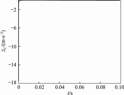
Fig. 6 Acceleration -
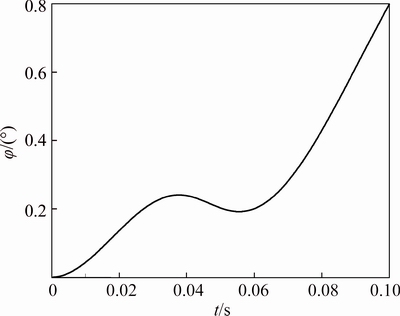
Fig. 7 Angle of undercarriage rotation around longitudinal main central axis of inertia O1x1-�� main central axis of inertia O1x1-
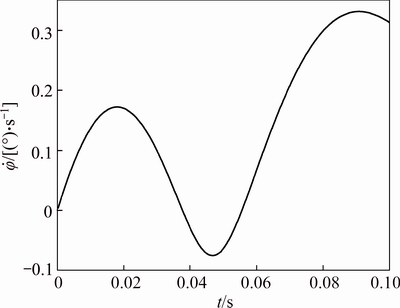
Fig. 8 Velocity of undercarriage rotation around longitudinal
Figures 10-12 shows an angle of rotation �� around transversal axis O1y1 of undercarriage. Amplitude of oscillating is acceptable, but in regard to change of this generalized coordinate it may be seen that it does not tend for calming, but it increases in the time observed.
The change of the angle of boom rotating of manipulator �� around axis O3y3 in joint of linking manipulator to undercarriage is shown in Figs. 13-15.
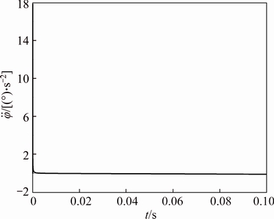
Fig. 9 Angle acceleration -

Fig. 10 Angle of undercarriage rotation around transversal main central axis of inertia O1y1-��
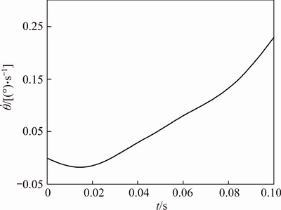
Fig. 11 Velocity of undercarriage rotation around transversal main central axis of inertia O1y1-
On the basis of the shown change of this angle, in the time observed an oscillating character is not seen and the tendency of value increase is expressed during the time.
Figures 16-18 show the change of an angle of arm rotation of manipulator �� around axis O4y4 in joint in the end of the boom. The amplitude of the shown change is in acceptable limits and has the tendency of growth.
Figures 19-21 show the change of an angle of manipulator bucket rotation �� around axis O5y5 of joint in the end of the arm. In the figure it may be seen that the change has no oscillatory character and that it has a tendency to grow during the time observed.

Fig. 12 Angle acceleration -

Fig. 13 Angle of boom rotation of manipulator around axis O3y3-��
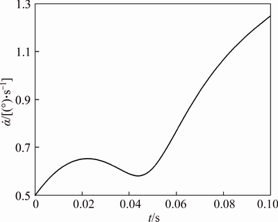
Fig. 14 Velocity of boom rotation of manipulator around axis O3y3-
Graphs of the changes of generalized coordinates, shown in Figures 10, 13 and 19 show that the system in observed time after excitation does not tend to calm but it enters resonance after 0.1 s. It is even confirmed that the system during one excitation, in an observed time interval, during one iteration, has free oscillating at one degree of freedom, and during the other iteration it has oscillation at the other degree of freedom. These facts point out that the system is dynamically unstable or it is at the limit of stability. The described appearance of free oscillating is confirmed in generalized coordinates ��, �� The change velocities of all the generalized coordinates in Figs. 5, 8, 11, 14, 17, and 20 show the oscillatory character.

Fig.15 Angle acceleration -
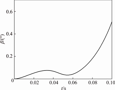
Fig. 16 Angle of arm rotation of manipulator around axis O4y4 of joint in end of boom -��

Fig. 17 Velocity of arm rotation of manipulator around axis O4y4 of joint in end of boom -

Fig. 18 Angle acceleration -
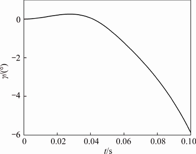
Fig. 19 Angle of bucket rotation of manipulator around axis O5y5 of joint in end of arm -��and ��.
Accelerations of all the generalized coordinates shown in Figs. 6, 9, 12, 15, 18, and 21 are approximately equal to zero without visible peaks.

Fig. 20 Velocity of bucket rotation of manipulator around axis O5y5 of joint in end of arm -

Fig. 21 Angle acceleration -
4 Conclusions
In this work dynamic behaviour of hydraulic excavator is analyzed. By using the dynamic- mathematical model we determined level and character of dynamic movings, velocities and accelerations.
Mathematical model of dynamic behaviour of hydraulic excavator is expanded by introducing new, sixth, generalized coordinate which represents rotation around transversal axis of undercarriage. By describing dynamic behaviour of hydraulic excavator by a system of nonlinear differential equations the analytical- mathematical model is improved, with which the simulation is closer to real excavator operating.
In the aim of further research of this problem it is necessary to research the effect of changes: rigidity in joints, mass, size and excitation position to dynamic behaviour. Also, experimental testing of dynamics of the observed system and comparing the test results to the results achieved by numerical simulation are of the special interest.
References
[1] ISO 10567, Earth-moving machinery, hydraulic excavators, lift capacity [S]. 2007.
[2]  D. Analysis of hydraulic excavator dynamic stability [C]// XVII International Conference on Material Flow, Machine and Devices in Industry, Belgrade, 2002.
[3] YUANBO L, QINGHUA H, DAQING Z. Dynamic analysis and simulation with Lagrange equation on hydraulic excavator [J]. Machine Tool & Hydraulics, 2006, 1001-3881(10): 170-171.
[4] FRIMPONG S, HU Y, INYANG H. Dynamic modeling of hydraulic shovel excavators for geomaterials [J]. International Journal of Geomechanics, 2008, 8(1): 20-29.
[5] VAHA P K, SKIBNIEWSKI M J. Dynamic model of an excavator [J]. Asce Journal of Aerospace Engineering, 1993, 6 (2): 148�C158.
[6] KOIVO A, THOMA M, KOCAOG-LAN E, ANDRADE-CETTO J. Modeling and control of excavator dynamics during digging operation [J]. Journal of Aerospace Eng, 1996, 9(1): 10�C18.
[7]  N. Dynamic analysis of the load lifting mechanisms [J].
  vestnik�CJournal of Machanical Engineering, 2008, 54(10): 655�C661.
[8] Park CHEOL-GYU, LIM KWANG-HO. A simulation environment for excavator dynamics [R]. Incheon, Republic of Korea: Daewoo Heavy Industries & Machinery Ltd., 2004: 401-702
[9] KAWABATA M, IMANISHI E. Dynamic strength analysis for hydraulic excavators [J]. Cobelco Technology Review, 2007, 27: 35-38.
[10] ALUJEVIC N, TOMAC I, GARDONIO P. Tuneable vibration absorber using acceleration and displacement feedback [J]. Journal of Sound and Vibration, 2012, 331(12): 2713-2728.
[11] PYUNG HUN C, SOO-JIN L. A straight-line motion tracking control of hydraulic excavator system [J]. Mechatronics, 2002, 12: 119-138.
[12] WSZOLEK G. Vibration analysis of the excavator model in GRAFSIM program on the basis of a block diagram method [J]. Journal of Materials Processing Technology, 2004, 157-158: 268-273.
[13] CVETICANIN L, MARETIC R, ZUKOVIC M. Dynamics of polymer sheets cutting mechanism [J]. Strojniski vestnik-Journal of Mechanical Engineering, 2012, 58(5): 354-360.
[14] XIAO L, SHUANG-Xia P, DONG-Yun W. Dynamic simulation and optimal control strategy for a parallel hybrid hydraulic excavator [J]. Journal of Zhejiang University SCIENCE A, 2008, 9(5): 624-632.
[15] MITREV R, GRUYCHEV R, POBEGAILO P. Cad/Cae investigation of a large hydraulic mining excavator [J]. Machine design, 2011, 3(1): 17-22.
[16] DRUGA C, BARBU D, LACHE S., Vibration and the human body [M]. Annals of the Oradea University, Fascicle of Management and Technological Engineering, Volume VI (XVI), 2007.
[17] KIM Ki-sun, KIM Jong-wan, KIM Kwang-joon. Dynamic modeling of seated human body based on measurements of apparent inertia matrix for fore-and-aft/vertical/pitch motion [J]. Journal of Sound and Vibration, 2011, 330(23): 5716-5735.
[18] WEI Y, PEIEN F, DATOG Q. Investigation on dynamic structural modification of hydraulic excavator work device [J]. Engineering Science, 2005, 7(9): 30�C33.
(Edited by DENG L��-xiang)
Cite this article as: Vujic Dragoljub, Lazarevic Olgica, Batinic Vojislav. Development of dynamic-mathematical model of hydraulic excavator [J]. Journal of Central South University, 2017, 24(9): 2010�C2018. DOI: https://doi.org/10.1007/ s11771-017-3610-x.
Received date: 2016-03-01; Accepted date: 2016-09-29
Corresponding author: Vujic Dragoljub, Professor; Tel: +00381648042002; E-mail: dragoljub.vujic@vti.vs.rs

