Trans. Nonferrous Met. Soc. China 27(2017) 733-740
Microstructure and mechanical properties of interface between laser cladded Hastelloy coating and steel substrate
Qin-ying WANG1, Yu-chen XI1, Xiao-yu LIU1, Shuang LIU1, Shu-lin BAI2, Zong-de LIU3
1. School of Materials Science and Engineering, Southwest Petroleum University, Chengdu 610500, China;
2. Department of Materials Science and Engineering, College of Engineering, Peking University, Beijing 100871, China;
3. Key Laboratory of Condition Monitoring and Control for Power Plant Equipment, Ministry of Education, North China Electric Power University, Beijing 102206, China
Received 23 December 2015; accepted 7 July 2016
Abstract: In order to improve the corrosion resistance of carbon steel, Hastelloy coatings were prepared on E235 steel substrate by a high power diode laser with laser scanning speeds of 6 and 12 mm/s, respectively. The interface between the coating and substrate was firstly exposed by dissolving off the substrate. Its microstructure, composition and mechanical properties were systemically studied. Special ��edges�� along the grain boundary were found at coating/substrate interface. These ��edges�� consisted of intergranular corrosion area and real grain boundary. The interface of coating mainly displayed austenite structure ascribed to the rapid solidification as well as the dilution of Ni during preparation. Additionally, Hastelloy coating and its interface prepared at the speed of 12 mm/s showed higher hardness than that prepared at the speed of 6 mm/s. Grain boundaries had higher friction coefficient than grains at both coating/substrate interfaces. Moreover, the interface at higher laser scanning speed exhibited smaller grains, lower dilution rates of Ni and Fe as well as a better tribological property.
Key words: Hastelloy coating; laser cladding; interface; microstructure; nano-scratch
1 Introduction
Coating has become an efficient way to cut the cost and widen the applications of various materials, such as organic, metallic, ceramic and composite materials [1-4]. Coatings are normally endowed with exceptional performances of high hardness, superior wear resistance and excellent anticorrosion property [5-8]. To realize the preparation of metallic, ceramic and composite coatings, thermal techniques, such as vacuum arc melting, plasma spraying and laser cladding, were applied [9-11]. However, some of them are less than satisfactory due to the existence of defects like pores and cracks at the interface of the as-prepared coatings, while this weak coating/substrate interface is particularly demanded to be improved.  et al [12] carried out a detailed research on the hardness and adhesion strength of the interface between the coatings WC/C and TiAlN, the combination of which was deposited on the steel. They found that the micro-hardness and adhesion strength of combined thick interlayer were higher than that of the single top WC/C layer. AWAN and HASAN [13] reported the morphology variation and phase transition at the interface between the aluminized layer and steel with the addition of silicon and the diffusion of carbon. Additionally, interface properties, such as degradation, adhesion strength and phase composition were also investigated by TOLPYGO et al [14], YAN et al [15] and WINDMANN et al [16]. The coatings in their studies were mainly prepared by chemical vapor deposition, physical vapor deposition and hot dipping. In terms of the interface morphology, the cross-section microstructure of the coating was usually used to illustrate it in previous researches [17,18].
As one of the most anticorrosion alloys, Hastelloy is widely used for corrosion prevention, e.g., marine facilities, chemical equipment, in corrosive environment. In recent decades, Hastelloy coatings have been developed by various thermal techniques, and the satisfied corrosion resistance was obtained [19,20]. However, there has so far been relatively little intensive study conducted at the interface between Hastelloy coating and steel substrate. Hence, it will be informative and beneficial for better understanding the microstructural evolution of coating during laser process by exposing its interface. Meanwhile, the microstructure features and mechanical properties of the interface are worth of being figured out.
This work aims at investigating the interface by a new view angle, i.e., from the normal surface of interface, which is different from the traditional one. Hastelloy coatings were prepared on steel substrate by laser cladding with different laser scanning speeds, and then the microstructure and mechanical property of the coating/substrate interface were studied.
2 Experimental
2.1 Material preparation
The well mixed Hastelloy powders (30-50 ��m in diameter) and E235 (ISO630) steel were used as coating material and substrate, respectively. The chemical compositions of the above powders and steel are given in Table 1. Prior to laser cladding, first, the well mixed powders were preset on the clean surface of the steel substrate, and then a steel plate was used to press and scrape the powders until its thickness was around 1 mm. The laser parameters were as follows: laser power of 3 kW, laser dot diameter of 8 mm, overlap ratio of 35%. The coatings prepared at scanning speeds of 6 mm/s and 12 mm/s were separately named as Hc-1 and Hc-2. The as-achieved coating/substrate bulk samples were cut into the sizes of 10 mm �� 10 mm �� 4 mm. Coatings were ground by 2000# abrasive papers and polished by corundum powders of 3-5 ��m in diameter, and then were corroded for 40 s by aqua regia (V(HNO3)/V(HCl)=1/3) for microstructure observation. In addition, the entire steel substrate (4 mm in thickness) of the coating was dissolved by a dilute nitric acid of 2 mol/L, as the schematic diagram shown in Fig. 1. Finally, the interface between the coating and substrate was exposed for observation and investigation. The interfaces corresponding to coatings Hc-1 and Hc-2 were named as Hi-1 and Hi-2, respectively.
2.2 Experimental method
Microstructure, element distribution and phase composition of the as-prepared coatings were measured by a scanning electron microscope (SEM, S-4800 Hitachi) equipped with energy dispersive X-ray spectrometer (EDS, Bruker 5010) and X-ray diffractometer (XRD, DMAX-2400, Rigaku) with Cu K�� radiation (0.15406 nm) operated at 40 kV, 100 mA and a scanning rate of 6 (��)/min.
In order to investigate the hardness variation of the coating��s normal surface at different thicknesses, the coating was successively polished away by the thickness of 0.3, 0.6 and 0.9 mm, and then the hardness was measured by a Vickers hardness tester (HMV-2T, Japan) under a load of 0.98 N and a dwell time of 15 s. Triboindenter system (Hysitron Inc., USA) with a 60�� cono spherical diamond tip (~1 ��m in diameter) was used in nano-scratch test, for which a constant load of 1000 ��N and a displacement velocity of 0.33 ��m/s were adopted. During testing, the temperature was ~25 ��C and the relative humidity was ~50%.
3 Results and discussion
3.1 Microstructure and composition
Microstructures of Hastelloy coatings Hc-1 and Hc-2 as well as interfaces Hi-1 and Hi-2 are shown in Fig. 2, in which three different features can be observed. First, as laser scanning speed increases, interface becomes more uneven, as shown in Figs. 2(a) and (b).
Table 1 Chemical compositions of Hastelloy powders and E235 steel (mass fraction, %)
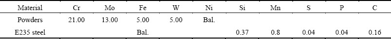
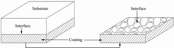
Fig. 1 Schematic diagram of chemical dissolving
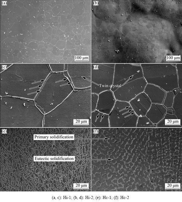
Fig. 2 Microstructures of interfaces and coating surfaces
Second, special ��edges�� around grain boundaries at interfaces are found, as indicated by the arrows in Figs. 2(c)-(d), which are not observed inside the coatings. Moreover, interface Hi-1 displays larger grain than interface Hi-2. For comparison, the microstructures inside the two coatings are composed of primary and eutectic solidifications, and show much smaller grains than the corresponding interfaces, as provided by Figs. 2(e)-(f). Meanwhile, the grains in coating Hc-1 are also larger than that in coating Hc-2, the reason for which has been fully discussed in the previous study [2].
The first phenomenon above is considered to be caused by the difference in laser scanning speed. The melt pool at interface caused by the heat shock from laser with higher scanning speed does not have enough time to develop uniformly, and thus solidified unevenly. By contrast, the melt pool at relatively low laser scanning speed can fully develop and thus form relatively smooth interface. To further investigate the above phenomena, the interfaces were corroded by aqua regia. Only the microstructural details of the interface Hi-1 are provided here because interfaces Hi-1 and Hi-2 have the similar microstructural feature and formation mechanism.
Figure 3(a) demonstrates the enlarged views of special ��edges�� along grain boundaries at interface Hi-1. Some boundaries contain three edges, and the edge in the middle is believed to be a continuous intergranular corrosion area, while the other two on either side are thought to be the real grain boundaries according to Fig. 3(b). In terms of the boundaries with the feature of two edges (Fig. 3(c)), they are regarded to contain an intergranular corrosion area and a real grain boundary. The two and three edges around grain boundaries are suggested to be formed randomly during coating solidification and substrate dissolving.
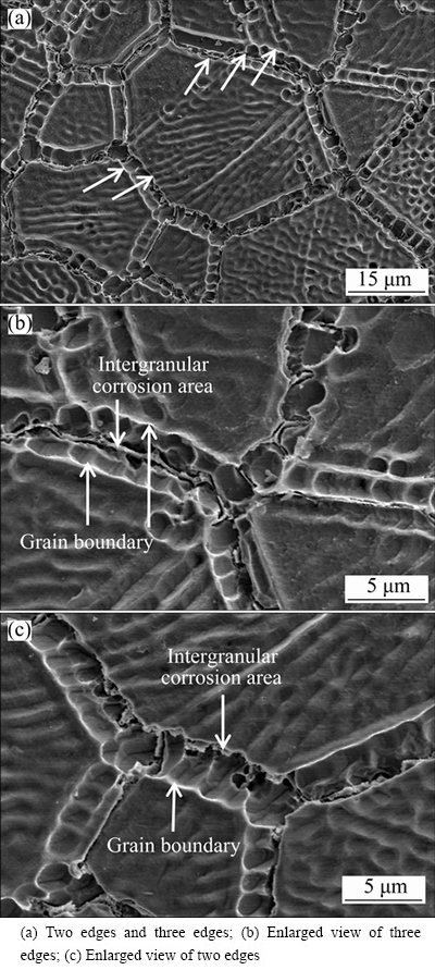
Fig. 3 Microstructures of interface Hi-1 after corrosion
To explain the phenomena of large grains observed at interface instead of inside the coating, the analysis based on the ingredient supercooling is provided in detail. Ingredient supercooling is caused by redistribution of solutes in front of the solid/liquid interface, in which the temperature of the melt is lower than practical liquid temperature. Ingredient supercooling increases with the distance away from the substrate to the coating surface. At interface, coating has the same ingredient supercooling with the substrate, and thus the microstructure of the interface is directly affected by the substrate, i.e., the large grains were observed. OCELIK et al [21] had the similar conclusion that the coating grain size and orientation at the interface were directly determined by the substrate grain size and orientation at the moment of coating solidification. Additionally, the polygonal grain with twin crystals (see Figs. 2(c)-(d)) is a particular feature of the austenite microstructure which possibly formed at the coating/substrate interface after laser process. Actually, as a high temperature phase, austenite in mild steel cannot be retained by slow cooling. Two reasons are considered to cause austenite in ambient temperature. First, fast cooling from laser cladding may lead to the carbon-rich austenite [22]; second, the dilution of Ni from coating at interface increases the austenite area, and thus helps to retain austenite [23]. Gradually, the ingredient supercooling becomes increasingly important with the distance away from the interface, and thus the microstructural development will be free from the effect of substrate and is immediately followed by columnar and dendritic growth.
For the purpose to determine the specific location of the interface obtained in this work, the cross-section of the coating Hc-1 after removing the substrate is given in Fig. 4. The planar solidification is found at the interface with the thickness around 10 ��m. It demonstrates that the interface is the normal surface of planar solidification. In addition, grain boundaries are also visible within the cross-section of the planar region, as indicated by the arrows. The planar region contains two layers of grains, above which the columnar and dendritic solidifications fully develop. The cross-sectional feature in microstructure here is consistent with that observed on the normal surface of the interface discussed above.
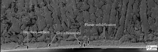
Fig. 4 Cross-section microstructure of Hi-1 coating at interface
XRD patterns of the interfaces and the coatings are presented in Fig. 5. Similar diffraction peaks in patterns can be observed for the four samples. The peaks are mainly ��-Ni with the solution of Cr, Mo and W. Additionally, the contents of crystal planes are different for coating and coating/substrate interface. Specifically, crystal plane (200) is preferential in both coatings with the percentage of 76%-86%, while crystal plane (111) exists preferentially at both interfaces with the percentage of 66%-73%. It is owed to the different solidification conditions for these two cases. At the interface, the ingredient supercooling is small, and thus the growth of crystal facet (111) is promoted, while the large ingredient supercooling inside the coating enhances the development of crystal plane (200).
The cross-section microstructures of coatings Hc-1 and Hc-2 are shown in Fig. 6. The planar solidification as well as the columnar and dendritic solidifications observed in Fig. 4 can be also seen here, from which the location of the interface obtained is clearly determined. Also, the thickness of the two coatings is 0.6-0.8 mm, while coating Hc-2 displays a similar cross-section microstructure as coating Hc-1. Additionally, thermal process usually worsens the element dilution at interface, and thus the effects of laser scanning speed on the dilution rates of elements at the interface are evaluated, as the data given by Fig. 7. The dilution rates of the main elements Ni and Fe can be calculated by the equation below [24]:

 (1)
(1)
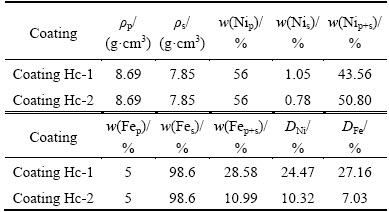
where D is the diffusion rate; ��p and ��s are the density of powders and substrate, respectively. w(Xp), w(Xs) and w(Xp+s) are the mass fractions of X element in powders, steel substrate and laser cladding coating (obtained from Fig. 7), respectively. The material densities, element contents and diffusion rates of coatings Hc-1 and Hc-2 are listed in Table 2.

Fig. 5 XRD patterns of coatings and interfaces
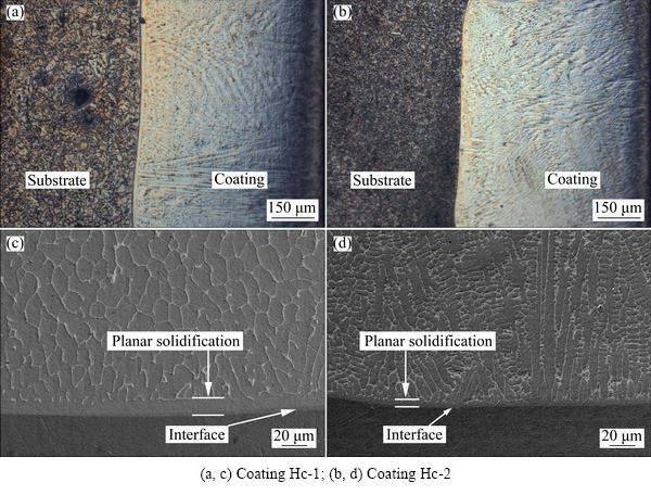
Fig. 6 Metallographs (a, b) and SEM images (c, d) of cross-sections for coatings
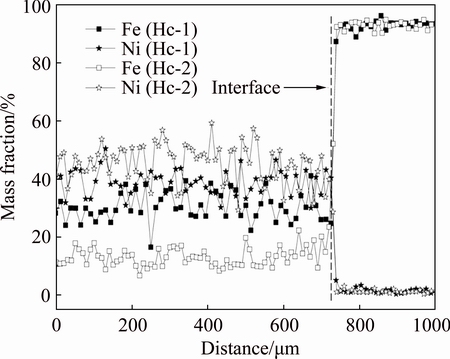
Fig. 7 Distribution of Ni and Fe across interfaces of coatings
Table 2 Densities, element contents and calculated diffusion rates of coatings Hc-1 and Hc-2
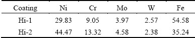
Considering Table 2, coating Hc-1 displays higher dilution rates of Ni and Fe than those of coating Hc-2. This implies that low laser scanning speed increases the dilution of main elements, which is consistent with the results obtained by other researchers [25,26]. Also, the above dilution of Ni well proves the mechanism of retaining austenite structure of coating at interface. As the element distributions at the interface given in Table 3, the content of Ni is 29.83%-44.47% at two interfaces. High content of Fe can also be found, and it is even more than 50% at interface Hi-1. This is basically caused by lower laser scanning speed, during which the coating owns longer time for thermal diffusion of elements. Additionally, the current interface is like a kind of Fe-Ni alloy with austenite structure. It experienced a heating process during laser preparation, which may lead to the precipitation of easily corroded structures or the harmful Cr/Mo-rich carbides at grain boundaries, in which Cr and Mo may be from the element diffusion at interface, finally, causing the serious intergranular corrosion, as shown in Fig. 3.
Table 3 Contents of main elements at coating interface (mass fraction, %)
3.2 Mechanical properties
Hardnesses measured on the normal surface of coating at different thicknesses are presented in Fig. 8. It can be seen that the hardness tends to decrease near the interface. The maximum hardness of coating Hc-2 is 37.5% higher than that of coating Hc-1. In addition, the hardness at interface is the lowest, and they are around HV0.1 190 and HV0.1 270 for Hi-1 and Hi-2, respectively. More compact microstructure by higher laser scanning speed is believed to cause the higher hardness for coating Hc-2 and the corresponding interface [2]. As the depth deepens, the grains on the normal surface of coating become larger owing to the small ingredient supercooling, which causes the microstructure less compact, and thus the hardness decreases.

Fig. 8 Hardness at normal surfaces of coatings along thickness
To further investigate the mechanical property of the interface, nano-scratch tests by nano-indentation were carried out. Initially, scratch images and the curves of friction coefficients at cross-sections of coatings are presented in Fig. 9. It can be seen that the grooves caused by scratch for two coatings can be divided into three regions, which correspond to coating, planar region and substrate accordingly. Also, the curves of friction coefficients show different features based on the above different regions. For each coating, the friction coefficient of coating is similar to that of planar region, while both of which are lower than that of substrate. It indicates a better tribological property of the former two regions. Moreover, apart from the similar friction coefficients (around 0.4) at substrates for two coatings, coating Hc-2 shows lower friction coefficients at coating and planar region (around 0.25) than coating Hc-1 (around 0.3). Normally, although coating shows different structures at planar region and the inside of the coating, their compositions are similar, which leads to the close friction coefficient of these two regions for each coating. While, substrate owns much larger grain size than coating as well as with more than 98% Fe in composition, and thus shows higher friction coefficient than two coatings. Moreover, the microstructure of coating is more compact at higher laser scanning speed [2], which causes coating Hc-2 having lower friction coefficient than coating Hc-1. Additionally, the position of the interface obtained between the coating and substrate is denoted by the thick dash lines in Fig. 9.
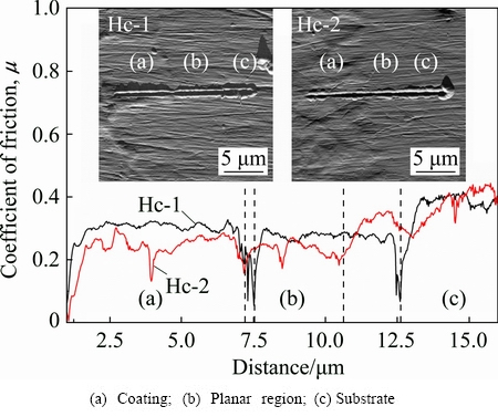
Fig. 9 Nano-scratch images and curves of friction coefficient at cross-sections of coatings
Actually, the scratch test at the interface of coating is not so meaningful for the application of coating/ substrate materials, but the results still help fully understand the feature of mechanical property at each region in laser coating, as shown in Fig. 10. It can be seen that the groove at interface Hi-1 is generally deeper and wider than that at interface Hi-2. This means that the former is less resistant to nano-scratch than the latter. Moreover, the grains and grain boundaries at both interfaces display different amounts of groove ridge volume. The larger ridge volume at grain boundaries indicates relatively low scratch resistance than that of grains. Generally, the grains at interface Hi-1 show higher friction coefficient than that at interface Hi-2 with the average values of 0.32 and 0.25, respectively, revealing better tribological property of interface Hi-2. At boundaries, the friction coefficients drop to zero after an abrupt rise to 0.48 and 0.42 at interfaces Hi-1 and Hi-2, respectively. The vanishing of friction coefficients at boundaries signifies the steep cliff in microstructure. Moreover, the average friction coefficients obtained for two interfaces are close to that of the coatings in Fig. 9.
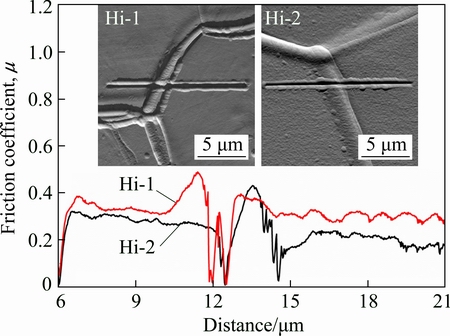
Fig. 10 Nano-scratch images and curves of friction coefficient at interfaces
4 Conclusions
1) Hastelloy coatings display austenite structure at interface. It is caused by the rapid solidification during laser process as well as the dilution of Ni from the coating. Additionally, special ��edges�� along grain boundaries at the interface of coating were found. They are determined to be intergranular corrosion area and real grain boundary. The formation mechanisms are considered to be related with the ingredient supercooling, effect of substrate as well as the precipitation of harmful phases at grain boundary during solidification.
2) With the increase of laser scanning speed, the grains in both interface and coating become smaller, the dilution rates of Fe and Ni at interfaces decrease, the hardnesses at cross-sections of coatings increase, the friction coefficients of both interfaces and coatings decrease, while the friction coefficient of the substrate was nearly not changed. Additionally, the grains show better tribological property than the grain boundaries at both coating/substrate interfaces.
References
[1] HU R G, ZNANG S, BU J F, LIN C J, SONG G L. Recent progress in corrosion protection of magnesium alloys by organic coatings [J]. Progress in Organic Coatings, 2012, 73: 129-141.
[2] WANG Q Y, ZHANG Y F, BAI S L, LIU Z D. Microstructures, mechanical properties and corrosion resistance of Hastelloy C22 coating produced by laser cladding [J]. Journal of Alloys and Compounds, 2013, 552: 253-258.
[3] CAIRO C A A, GRAC M L A, SILVA C R M, BRESSIANI J C. Functionally gradient ceramic coating for carbon�Ccarbon antioxidation protection [J]. Journal of the European Ceramic Society, 2001, 21: 325-329.
[4] MANDELLI A, BESTETTI M, FORNO A D, LECIS N, TRASATTI S P, TRUEBA M. A composite coating for corrosion protection of AM60B magnesium alloy [J]. Surface and Coatings Technology, 2011, 205: 4459-4465.
[5] KOBAYASHI A. Formation of high hardness zirconia coatings by gas tunnel type plasma spraying [J]. Surface and Coatings Technology, 1997, 90: 197-202.
[6] PALDEY S, DEEVI S C. Single layer and multilayer wear resistant coatings of (Ti,Al)N: A review [J]. Materials Science and Engineering A, 2003, 342: 58-79.
[7] SZCZYGIEL B, KOLODZIEJ M. Composite Ni/Al2O3 coatings and their corrosion resistance [J]. Electrochimica Acta, 2005, 50: 4188-4195.
[8] XUAN H F, WANG Q Y, BAI S L, LIU Z D, SUN H G, YAN P C. A study on microstructure and flame erosion mechanism of a graded Ni-Cr-B-Si coating prepared by laser cladding [J]. Surface and Coatings Technology, 2014, 244: 203-209.
[9] KARANTZALIS A E, LEKATOU A, TSIRKA K. Solidification observations and sliding wear behavior of vacuum arc melting processed Ni-Al-TiC composites [J]. Materials Characterization, 2012, 69: 97-107.
[10] GUIGNARD A, MAUER G,  R, STOVER D. Deposition and characteristics of submicrometer-structured thermal barrier coatings by suspension plasma spraying [J]. Journal of Thermal Spray Technology, 2012, 21: 416-424.
[11] CANDEL J J, AMIGO V, RAMOS J A, BUSQUETS D. Sliding wear resistance of TiCp reinforced titanium composite coating produced by laser cladding [J]. Surface and Coatings Technology, 2010, 204: 3161-3166.
[12] B, PANJAN P, CEKADA M, QUINTO D T. Interface characterization of combination hard solid lubricant coatings by specific methods [J]. Surface and Coatings Technology, 2002, 154: 194-203.
[13] AWAN G H, HASAN F U. The morphology of coating/substrate interface in hot-dip-aluminized steels [J]. Materials Science and Engineering A, 2008, 472: 157-165.
[14] TOLPYGO V K, CLARKE D R, MURPHY K S. Evaluation of interface degradation during cyclic oxidation of EB-PVD thermal barrier coatings and correlation with TGO luminescence [J]. Surface and Coatings Technology, 2004, 188-189: 62-70.
[15] YAN B, LOH N L, FU Y, SUN C Q, HING P. Surface and interface characterization of diamond coatings deposited on pure titanium [J]. Surface and Coatings Technology, 1999, 115: 256-265.
[16] WINDMANN M, ROTTGER A, THEISEN W. Phase formation at the interface between a boron alloyed steel substrate and an Al-rich coating [J]. Surface and Coatings Technology, 2013, 226: 130-139.
[17] WANG R, QIAN Y, LIU J. Interface behavior study of WC92-Co8 coating produced by electrospark deposition [J]. Surface Science, 2005, 240: 42-47.
[18] LUO P, DONG S, XIE Z, YANG L A, YANG W. The effects of coating parameters on the quality of TiB2�CTiC composite phase coating on the surface of Cu-Cr-Zr alloy electrode [J]. Surface and Coatings Technology, 2014, 253: 132-138.
[19] WANG Q Y, BAI S L, LIU Z D. Corrosion behavior of Hastelloy C22 coating produced by laser cladding in static and cavitation acid solution [J]. Transactions of Nonferrous Metals Society of China, 2014, 24: 1610-1618.
[20] ZOCCO A, PERRONE A, VIGNOLO M F, DUHALDE S, AVRAM I, MORALES C, PEREZ T. High quality Hastelloy films deposited by XeCl pulsed laser ablation [J]. Applied Surface Science, 2003, 208-209: 669-675.
[21] OCELIK V, FURAR I, HOSSON J T M D. Microstructure and properties of laser clad coatings studied by orientation imaging microscopy [J]. Acta Materialia, 2010, 58(20): 6763-6772.
[22] RYU H B, SPEER J G, WISE J P. Effect of thermomechanical processing on the retained austenite content in a Si-Mn transformation-induced-plasticity steel [J]. Metallurgical and Materials Transactions A: Physical Metallurgy and Materials Science A, 2002, 33: 2811-2816.
[23] KIM S, LEE C, OH C. Effect of Cu, Cr and Ni on mechanical properties of 0.15 wt.% C TRIP-aided cold rolled steels [J]. Scripta Materialia, 2003, 48: 539-544.
[24] WANG K L, ZHANG Q B, SUN M L, WEI X G, ZHU Y M. Rare earth elements modification of laser-clad nickel-based alloy coatings [J]. Applied Surface Science, 2001, 174: 191-200.
[25] KWOK C T, CHENG F T, MAN H C. Laser surface modification of UNS S31603 stainless steel. Part I: Microstructures and corrosion characteristics [J]. Materials Science and Engineering A, 2000, 290: 55-73.
[26] KWOK C T, MAN H C, CHENG F T. Cavitation erosion�Ccorrosion behaviour of laser surface alloyed AISI 1050 mild steel using NiCrSiB [J]. Materials Science and Engineering A, 2001, 303: 250-261.
�����۸����ϺϽ�Ϳ����������������֯����ѧ����
����Ӣ1�����1��������1���� ˫1��������2�����ڵ�3
1. ����ʯ�ʹ�ѧ ���Ͽ�ѧ�빤��ѧԺ���ɶ� 610500��
2. ������ѧ ��ѧԺ ���Ͽ�ѧ�빤��ϵ������ 100871��
3. ����������ѧ ��վ�豸״̬�������ƽ������ص�ʵ���ң����� 102206
ժ Ҫ��Ϊ���̼�ֵ���ʴ���ܣ����ø߹��������뵼�弤�����ֱ���6��12 mm/s���۸��ٶȣ���E235��̼�ֻ����ϳɹ��Ʊ��˹��ϺϽ�Ϳ�㡣����ϡ������Һ��ȥE235�ֻ����ü����۸�����ֻ���֮��Ľ��棬���Ըý��������֯����ѧ����Լ���ѧ���ܽ���ϵͳ�о����о�������Ϳ��/��������ϵľ��紦��������һ�����⡰��Ե�������������⡰��Ե������ʵ�����뷢�����縯ʴ�����µĸ�ʴ�ۼ�����ɡ�������Ҫ���ֳ��ɼ����۸���Ѹ����ȴ��NiԪ���������ɢ�����µİ�������֯�����⣬��12 mm/s�ļ����۸��ٶ��Ʊ���Ϳ�㼰������6 mm/s������Ʊ���Ϳ�㼰�������и��ߵ�Ӳ�ȣ���Ϳ��/��������ϵľ������Ӧ�ľ�����Ⱦ��и��ߵ�Ħ��������ͬʱ�������۸��ٶ�Խ�죬�����ϵľ����ߴ�ԽϸС�����洦Ni��Fe����ɢ�ٶ�Խ�ͣ�Ħ��ѧ����Խ���졣
�ؼ��ʣ����ϺϽ��۸��㣻�����۸������棻����֯��������
(Edited by Yun-bin HE)
Foundation item: Project supported by the New Staff Research Start-up Fund and the Innovation Fund (School of Materials Science and Engineering) of Southwest Petroleum University, China
Corresponding author: Yu-chen XI; Tel: +86-28-83037417; E-mail: xycsony3@126.com
DOI: 10.1016/S1003-6326(17)60081-5

