45�ֻ����ϼ����۸�Ni60A�Ͻ�Ϳ�������֯����Ħ��ѧ��Ϊ
��Դ�ڿ����й���ɫ����ѧ��(Ӣ�İ�)2015���5��
�������ߣ��� �� �� �� ̷С�� �� �� ����ï
����ҳ�룺1525 - 1532
�ؼ��ʣ������۸���Ni60A�Ͻ�45�Ÿ֣�����֯��Ħ��ѧ��Ϊ
Key words��laser cladding; Ni60A alloy; 45 steel; microstructure; tribological behavior
ժ Ҫ�����ü����۸�������45�Ÿֻ������Ʊ���������Ni60AͿ�㣬��ϸ�о�Ϳ������֯���������ԡ�����ɼ���ֲ���ϵͳ����Ϳ��ͻ����ڲ�ͬ�غ��»�����ĥGCr15��ʱ�ĸ���Ħ��ĥ����Ϊ�����������Ϳ������֯�������ܣ���Ҫ�ɦ�(Ni)�����塢������Ni-Ni3B��״������С��״M23C6�������ȷֲ���֦���乲����֯�еĺڵ�״CrB��ɣ�Ϳ����Ӳ��ԼΪ������Ӳ�ȵ�2.6������ͬ�غ������£�Ϳ��Ħ���������ڻ���Ħ����������Ħ�������ȶ����ڽϸ��غ�������(300 g)��Ϳ��ĥ����Ϊ���ĵ�1/6.2������ĥ�����Ϊճ��ĥ��ĥ��ĥ���������Ա��μ�����ĥ�𣬶�Ϳ��ĥ�������Ϊ����ĥ��ĥ����еȳ̶ȵ�����ĥ��
Abstract: The crack-free Ni60A coating was fabricated on 45 steel substrate by laser cladding and the microstructure including solidification characteristics, phases constitution and phase distribution was systematically investigated. The high temperature friction and wear behavior of the cladding coating and substrate sliding against GCr15 ball under different loads was systematically evaluated. It was found that the coating has homogenous and fine microstructure consisting of ��(Ni) solid solution, a considerable amount of network Ni-Ni3B eutectics, M23C6 with the floret-shape structure and CrB with the dark spot-shape structure uniformly distributing in interdendritic eutectics. The microhardness of the coating is about 2.6 times as much as that of the substrate. The coating produces higher friction values than the substrate under the same load condition, but the friction process on the coating keeps relatively stable. Wear rates of the coating are about 1/6.2 of that of the substrate under the higher load (300 g). Wear mechanism of the substrate includes adhesion wear, abrasive wear, severe plastic deformation and oxidation wear, while that of the coating is merely a combination of mild abrasive wear and moderate oxidation wear.
Trans. Nonferrous Met. Soc. China 25(2015) 1525-1532
Jian ZHANG, Yu HU, Xiao-jun TAN, Liang GUO, Qing-mao ZHANG
Guangdong Key Laboratory of Nanophotonic Functional Materials and Devices, South China Normal University, Guangzhou 510006, China
Received 27 May 2014; accepted 9 October 2014
Abstract: The crack-free Ni60A coating was fabricated on 45 steel substrate by laser cladding and the microstructure including solidification characteristics, phases constitution and phase distribution was systematically investigated. The high temperature friction and wear behavior of the cladding coating and substrate sliding against GCr15 ball under different loads was systematically evaluated. It was found that the coating has homogenous and fine microstructure consisting of ��(Ni) solid solution, a considerable amount of network Ni-Ni3B eutectics, M23C6 with the floret-shape structure and CrB with the dark spot-shape structure uniformly distributing in interdendritic eutectics. The microhardness of the coating is about 2.6 times as much as that of the substrate. The coating produces higher friction values than the substrate under the same load condition, but the friction process on the coating keeps relatively stable. Wear rates of the coating are about 1/6.2 of that of the substrate under the higher load (300 g). Wear mechanism of the substrate includes adhesion wear, abrasive wear, severe plastic deformation and oxidation wear, while that of the coating is merely a combination of mild abrasive wear and moderate oxidation wear.
Key words: laser cladding; Ni60A alloy; 45 steel; microstructure; tribological behavior
1 Introduction
In order to meet the need in different service environments, many engineering components require excellent surface properties such as high wear and corrosion resistance. These performances can be obtained by laser cladding alloys powder on low cost substrate surface [1-4]. Nickel-based alloys coatings, with high bonding strength, better corrosion behavior and excellent resistance to adhesive and abrasive wear, have promising applications in engineering [5-7]. Previous researches [8,9] confirmed that NiCrBSi colmonoy alloys (for n(Si)/n(B) ratios less than 3) have a tendency to develop multiple microstructures under different cooling rates, e.g., different cladding speeds or substrate temperatures. Abundance of hard Cr-rich precipitates and eutectic structures which are fabricated under high cooling rate produce high hardness levels but at the same time provide easy routes for crack propagation. With the decrease of cooling rate, Cr-rich precipitates are gradually eliminated, the eutectic network is substantially diminished and crack-free coating can be fabricated, but hardness levels decrease. In addition, COCKERAM [10] found that NiCrBSi colmonoy alloys (For n(Si)/n(B) ratios less than 3) have lower fracture toughness values in comparison to their Co- or Fe-based counterparts. Therefore, it is necessary to get the specific cladding Ni60A microstructure, which is crack-free and well combines the hardness and the toughness, and study the characteristics of this microstructure. Moreover, 45 steel as high-quality carbon structural steel, is the main material for shaft parts. Such parts often run at a high temperature and high stress environment, if the wear resistance is insufficient, they will fail [11,12]. Despite the growing application of these alloys in laser cladding, there is not much data available in the literature about the correlation between this microstructure, friction and wear behavior of the laser cladding Ni60A coating, in particular, under different loads and elevated temperature.
Therefore, an attempt was made to characterize the microstructure of Ni60A alloys (for n(Si)/n(B) ratios less than 3) coating with large area on 45 steel substrate by laser cladding, also under different loads conditions, and the high temperature friction and wear behavior of the substrate and those of laser cladding coatings were comparatively investigated.
2 Experimental
2.1 Materials and fabrication of laser cladding coating
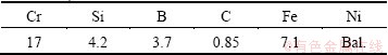
The material used in this experiment was Ni60A alloy powder, with an average size of 50-100 ��m, and a melting point of 960-1040 ��C. Its chemical composition is listed in Table 1. Normalized 45 medium steel with dimensions of d65 mm �� 10 mm was used as the substrate.
Table 1 Chemical composition of Ni60A alloy powder (mass fraction, %)
Laser cladding coatings with a 33% overlap were fabricated with a YLS-4000-S2T-CL type 4 kW IPG fiber laser processing system equipped with an ABB 2400 type 6-axis robot. The powder feeder was the DPSF-3 off-axial auto-feeding powder device. A shielding of Ar gas with a flow rate of 10 L/min was used to blow the powders into the molten pool. The powder nozzle was set at an angle of 35�� with respect to the surface normal of the substrate. The optimizing process parameters were selected as laser power of 3.2 kW, beam scanning speed of 600 mm/min, powder feeding rate of 9.0 g/min, and beam diameter of 4 mm.
2.2 Microstructural characterization
After laser cladding, samples were cut from the transversal cross sections of the coating. The samples for OM and SEM observations were prepared using standard mechanical polishing procedures in association with etching in aqua regia at room temperature. Microstructures of the coating and the crack were observed by optical microscope (OM). In addition, the microstructural details were analyzed by ZEISS ULTRA 55 type scanning electron microscope (SEM), the chemical composition was analyzed with an Oxford X-Max 50 type energy dispersive spectroscopy (EDS) microprobe (20 kV, energy resolution better than 129 eV of Mn K��). The phase composition was identified by using a D8 Advance X-ray diffractometer (XRD, 40 kV, 40 mA, Cu K�� radiation, scanning within 2��=10��-90��). The hardness profile along the depth direction and surface microhardness of coating were determined using an MH-5 Vickers microhardness tester, at a load of 200 g and dwell time of 20 s.
2.3 Wear testing
The friction and wear behavior of 45 steel substrate and laser cladding coating (dimensions of d65 mm��10 mm) as lower sample against GCr15 ball (a hardness of HRC 62-65, diameter of 3 mm) as upper sample was tested on an HT-500 pin-on-disk dry sliding wear tester. Experimental parameters of wear test are shown in Table 2. The friction coefficient was continuously recorded by the computer connected to the tester; and the wear width and the wear depth of the wear scars were measured by a TALYSURF CLI 1000 non-contact surface roughness profiler which picked spots per 1 ��m from the wear scars. The wear volume was determined by the depth and width of the wear scars. Therefore, the wear volume ��V could be calculated from [13],
 (1)
(1)
where L0refers to the circumference of wear scar, r refers to the radius of the GCr15 steel ball, and d refers to the width of the wear scar.
Then, the wear rate �� of the coating was calculated from [14]
 (2)
(2)
where v refers to the linear velocity of the low sample, t refers to the wear time and N refers to the load. For the observation of the worn structures, the morphologies of the worn surface and the wear debris generated were examined by SEM and EDS.
Table 2 Experimental parameters of wear

3 Results and discussion
3.1 Microstructure of cladding Ni60A coating
Figure 1 shows cross-sectional OM morphologies of the Ni60A coating. It can be seen that a white bonding line (zone) with a thickness of 5 ��m is found at the coating/substrate interface and the coating is metallurgically bonded with 45 steel substrate. It also exhibits that the microstructure of coating is typical rapid solidification structure [4,15]. It can be seen that a planar growth with a thickness of 5 um and relatively coarse cellular are found at the coating/substrate interface (Fig. 1(a)). With an increase in distance from the surface of substrate, the columnar dendrites are observed in the middle of coating (Fig. 1(b)) and the equiaxed grains are observed at the top of coating (Fig. 1(c)). The result of the XRD analysis shown in Fig. 2 indicates that Ni60A coating is mainly composed of ��(Ni), FeNi3, M23C6 (M=Fe, Ni, Cr), CrB, and Ni3B. Moreover, Cr-rich precipitates with different shapes distributed in the matrix are not found by OM. They are likely to precipitate in an intergranular network of the coarse matrix and are enclosed by interdendritic eutectics. Meanwhile, a considerable amount of interdendritic eutectics also precipitate in an intergranular network of the coarse matrix. The previous studies have also shown the similar microstructure, and this microstructure is not only helpful for improving the toughness of coatings but also easily to prepare large-area crack-free coating under the condition of no preheating [8,9]. Based on previous studies, the formation mechanism of this microstructure may be explained. Under high laser power and low scanning speed, molten pool liquid retention time is longer and the cooling rate is relatively low, which results in a high Fe content of coating because of the substantial dilution of the steel substrate. In such a condition, excessively high Fe contents modify the solidification path of the alloy, suppress the primary boride and carbide phases at the beginning and diminish the interdendritic eutectics at the end of the solidification as it can be seen in microstructure of Fig. 1, such precipitates with different shapes distributed in the matrix are not found by OM. Meanwhile, the absence of porosity and microcracks shows that the process parameters selected in this work have ensured a high quality coating and the microstructure has a low crack sensibility.
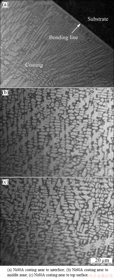
Fig. 1 Cross-sectional OM morphologies of Ni60A coating
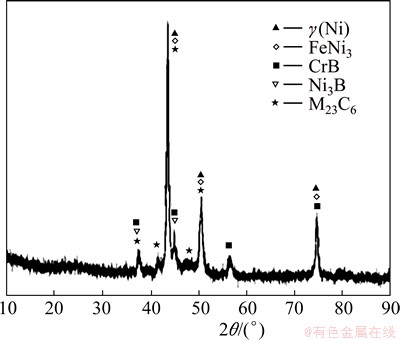
Fig. 2 XRD pattern of Ni60A coating
Although OM could provide a general overview of the microstructures, details of the constituent phases and their micro-morphologies could only be revealed by SEM. The microstructure shown in Fig. 3 is the typical feature of the Ni60A coating crystallized in hypoeutectic crystal mode under SEM, a considerable amount of network eutectics and Cr-rich precipitates locate in a large number of intergranular positions of the primary matrix. The structure of the coating is fine, uniform and close. Figures 3(b) and (c) show the magnified cross-sectional SEM images of the coating. It can be more clearly seen in Fig. 3(b) that the microstructure of the Ni60A coating contains two different zones respectively described as dendritic solid solution matrix (marked with A) and interdendritic precipitates. In addition, interdendritic precipitates contain at least three components: interdendritic eutectics with the rod-shape structure (marked with B), many flower-shape precipitates (marked with C) uniformly distributed in interdendritic eutectics and several dark spot-shape precipitates (marked with D) scattered in the flower-shape precipitates. Figure 3(c) exhibits details of interdendritic precipitates, where the rod-shape structure interdendritic eutectic phase with a length of 0.2-1 ��m, the floret-shape structure precipitates with a size of 0.5-3 ��m, and the dark spot-shape structure precipitates with a diameter of 0.1 ��m are better observed. The chemical compositions of various phases by SEM/EDS analysis are given in Table 3. According to the EDX measurements and the above mentioned XRD analysis, the matrix (marked with A in Fig. 3(b)) is a ��(Ni) solid solution with small quantities of Cr and Si, and rich in Fe, showing that a higher Fe content of coating can influence microstructure of the cladding coating [9]. The interdendritic eutectics (marked with B in Fig. 3(b)) may be identified as Ni-Ni3B eutectics with significant quantities of B. The floret-shape precipitates (marked with C in Fig. 3(b)) are identified as carbides M23C6(M=Fe, Ni, Cr) with significant quantities of Ni and Fe. The dark spot-shape precipitates (marked with D in Fig. 3(b)) are identified as borides CrB with fewer quantities of Ni and Fe.

Fig. 3 Cross-sectional SEM micrographs of Ni60A coating
Table 3 Chemical composition analysis of marked location in Fig. 3(b) (mass fraction, %)
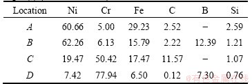
Figure 4 shows the microhardness profile along the depth direction of the Ni60A coating. It is seen that the average microhardness of the coating (approximately HV 530-580) is about 2.6 times as much as that of the 45 steel substrate (approximately HV 220), which is attributed to the formation of hard phases such as Cr23C6, CrB, Ni3B, and FeNi3 during laser cladding process [15]. But this microstructure prepared by optimizing process parameters has lower average microhardness than that of previous studies [9,12,16]. The main reason is that quantities of precipitates with different shapes distributed in the matrix are suppressed by high Fe contents, due to the dilution between coating and substrate. In particular, this microstructure helps to improve the toughness of the laser deposited coatings, to decrease the crack sensitivity, and crack-free laser cladding Ni60A coating will be easy to be obtained without preheating conditions [9]. The transition from the high values of the coating to the small values of substrate is a smooth gradient distribution, this is because a small region which is accordingly described as the binding zone interface (BZ, marked with A) and the heat affected zone (HAZ, marked with B) exists between the coating and substrate. Due to the dilution between the substrate and the coating, the hardness value (HV 363) of BZ is lower than that of the coating. Due to the occurrence of phase transformation on the surface of substrate, the hardness value (HV 260) of HAZ is higher than the initial one of substrate material.
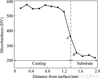
Fig. 4 Microhardness profile of Ni60A coating
3.2 High temperature friction and wear behavior
Figure 5 illustrates the friction response as a function of sliding time for the substrate (Fig. 5(a)) and the Ni60A coating (Fig. 5(b)). The 45 steel substrate keeps intensive and the instant friction response curve fluctuates rapidly. Especially, under applied loads of 200 g and 300 g, friction coefficients fluctuate rapidly for sliding against the 45 steel substrate. The friction pairs are composed of GCr15 steel ball and 45 steel substrate or the Ni60A coating. It can be observed that the friction coefficients of the substrate and the coating decrease with the increasing applied loads under the different load conditions. It is well known that in the investigated sliding systems, an increase in load caused a decrease in friction, which is attributed to the oxides produced under the higher load condition [16-19]. The contact surfaces of the substrate and the coating against GCr15 steel balls are easily oxidized to form oxides, due to dry sliding wear test conducted at high temperature, especially under the higher load. Oxides are known to reduce the critical shear stress at the contact points, thereby reducing friction in the sliding system. The presence of oxides is also confirmed in the subsequent studies. Sliding against the Ni60A coating produced higher friction coefficients than sliding against the 45 steel substrate under the same load condition, but the friction process on the Ni60A coating keeps relatively stable and the instant friction response curve is smooth, while the friction processing- in wear phase evolves into the severe wear phase during the whole wear process, while the Ni60A coating presents that the running-in wear phase evolves into the steady wear phase. It can be attributed to the fact that the Ni60A coating has a dense and uniform microstructure (Fig. 1 and Fig. 3) and a high microhardness (Fig. 4) as well as good high-temperature property, leading to the relatively stable friction coefficient during the friction and wear test. Under the same load condition, sliding against the 45 steel substrate produces lower friction values, it can be explained by the following reason, the 45 steel substrate has a much lower hardness than the Ni60A coating and thus is easily plastically deformed under the harder material (GCr15 ball), resulting in the formation of the smooth contact surface which helps to decrease the contribution of the ploughing component to friction [18].
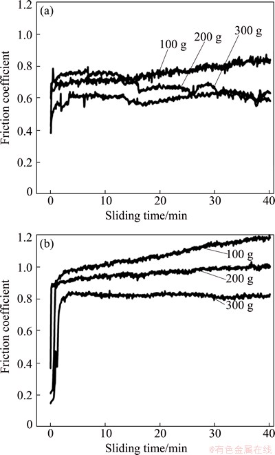
Fig. 5 Friction response as a function of sliding time for substrate (a) and Ni60A coating (b) under different loads
The wear rates of the 45 steel substrate and the Ni60A coating are shown in Fig. 6. It indicates that the Ni60A coating has much smaller wear rates than the 45 steel substrate under the same load condition, and wear rates of the Ni60A coating (4.8��10-5mm3/(N��m)) are about 1/6.2 of that of the 45 steel substrate (3.45��10-4 mm3/(N��m)) under the higher load (300 g). This indicates that the coating has excellent wear resistance than the substrate. Besides, the wear rates of the Ni60A coating decrease with the increasing applied loads, while the opposite is observed for the 45 steel substrate. The excellent wear resistance of the coating was primarily attributed to its microstructure, phase constitution, phase distribution and the friction and wear process. A considerable amount of carbides M23C6 and small amount of borides CrB uniformly distributed in the interdendritic eutectics rather than ��(Ni) matrix effectively reduce the number of wear debris formation at the contact zone, owing to the fracture of hard phases of boride and carbide under high stress, resulting in the stable friction process and the low wear rates. Meanwhile, uniform tough phases of ��(Ni) solid solution also help to depress dual actions which hard phases suffer from the inherent residual strain and the shear stress generated in the friction process. In this case, the total stress centralized on the hard phase is difficult to exceed its strength, resulting in the fracture of hard phases and the excessive wear debris formation in the contact zone. Combining the preceding friction analysis (Fig. 5), the wear rates of the 45 steel substrate follow the typical trend of increased loads, leading to the increase of wear rates [18], and the wear rates of the Ni60A coating follow the trend of increased friction coefficient, leading to the increase of wear rates. This results from the increased loads, leading to the acute fluctuation of the friction coefficients and the instability friction process for the 45 steel substrate. Thus, sliding against substrate suffered from the severe wear, resulting in higher wear rates of the substrate. For the Ni60A coating, although the load is increased from 100 g to 300 g, the friction coefficients of coating decrease and friction process keeps relatively stable. Thus, sliding against coating suffered from the steady wear, resulting in lower wear rates of the substrate.

Fig. 6 Wear rates of substrate and Ni60A coating under different loads
The SEM images of the worn surfaces of the substrate and the Ni60A coating in Fig. 7 indicate the different levels of surface deterioration experienced which are consistent with the wear rates results. It can be observed that the worn surface of the 45 steel substrate shows signs of fatigue spalling and scratching as well as some tiny grooves and severe plastic deformation on the edges of the wear scar, indicating that the 45 steel substrate experienced adhesion wear, abrasive wear, and severe plastic deformation (Especially, severe plastic deformation on the edges of the wear scar). Scratching and grooving are initially caused by the initial deformation of asperities on the contact surfaces. Subsequent scratching and grooving are caused through an abrasive wear mechanism by wear debris fragments and the surface of the GCr15 ball [18]. No sign of fatigue spalling and plastic deformation are visible on the worn surface of the Ni60A coating, and only a large amount of deep adhesive craters and fairly short continuous ploughing grooves, showing typical characteristic of abrasive mechanism [17]. This well corresponds to the better wear resistance of the Ni60A coating than that of the 45 steel substrate.

Fig. 7 SEM images of worn surfaces of substrate (a) and Ni60A coating (b) under applied load of 300 g
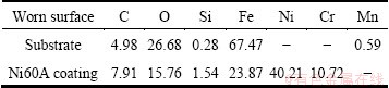
The chemical compositions of the worn surfaces of the substrate and the Ni60A coating, analyzed by EDS, are listed in Table 4. It can be seen that the both worn surfaces consist of a large amount of O and Fe, indicating that the severe oxidation wear during the whole wear process. Furthermore, the oxygen content in the worn surface of the substrate is higher than that in the worn surface of the Ni60A coating. This well corresponds to the better oxidation wear resistance of the Ni60A coating than that of the 45 steel substrate.
Table 4 Chemical compositions of worn surfaces of substrate and Ni60A coating (mass fraction, %)
4 Conclusions
1) The cladding Ni60A coating is metallurgically bonded to the substrate. It has homogenous fine microstructure consisting of ��(Ni) solid solution, a considerable amount of network Ni-Ni3B eutectics, M23C6 with the floret-shape structure and CrB with the dark spot-shape structure uniformly distributing in interdendritic eutectics. With increasing distance from the surface of substrate, ��(Ni) solid solution with a planar growth, column dendrites and the equiaxed grains are formed.
2) The average microhardness of the Ni60A coating is about 2.6 times as much as that of the substrate. The friction coefficients of the substrate and the coating decrease with increasing the applied loads. And the coating produces higher friction values than the substrate under the same load condition, but the friction process on the coating keeps relatively stable, while the friction process on the 45 steel substrate keeps relatively intensive.
3) The Ni60A coating has much smaller wear rates than the substrate under the same load condition, wear rates of the coating are 1/6.2 of that of the substrate under the higher load (300 g). Besides, the wear rates of the coating decrease with the increase of applied loads, while the opposite is observed for the substrate. High temperature wear mechanism of the substrate includes adhesion wear, abrasive wear, severe plastic deformation and oxidation wear, while the coating merely suffers from mild abrasive wear and moderate oxidation wear.
References
[1] MANNA I, MAJUMDAR J D, CHANDRA B R. Laser surface clad of Fe-B-C, Fe-B-Si and Fe-BC-Si-Al-C on plain carbon steel [J]. Surf Coat Tech, 2006, 201: 434-440.
[2] ZHOU S F, HUANG Y J, ZENG X Y, HU Q W. Microstructure characteristics of Ni-based WC composite coatings by laser induction hybrid rapid cladding [J]. Mater Sci Eng A, 2008, 480(1-2): 564-572.
[3] WANG Shan-li, CHENG Jing-chang, YI Seong-hoon, KE Li-ming. Corrosion resistance of Fe-based amorphous metallic matrix coating fabricated by HVOF thermal spraying [J]. Transactions of Nonferrous Metals Society of China, 2014, 24(1): 146-151.
[4] HUANG S W, SAMANDI M, BRANDT M. Abrasive wear performance and microstructure of laser clad WC/Ni layers [J]. Wear, 2004, 256(11-12): 1095-1105.
[5] SHARMA S P, DWIVEDI D K, JAIN P K. Effect of La2O3 addition on the microstructure, hardness and abrasive wear behavior of flame sprayed Ni based coatings [J]. Wear, 2009, 267(5-8): 853-859.
[6] CHALIAMPALIAS D, VOURLIAS G, PAVLIDOU E, SKOLIANOS S, CHRISSAFIS K, STERGIOUDIS G. Comparative examination of the microstructure and high temperature oxidation performance of NiCrBSi flame sprayed and pack cementation coatings [J]. Appl Surf Sci, 2009, 255(6): 3605-3612.
[7] WANG P Z, QU J X, SHAO H S. Cemented carbide reinforced nickel-based alloy coating by laser cladding and the wear characteristics [J]. Mater Des, 1996, 17(5-6): 289-296.
[8] HEMMATI I,  V, HOSSON J T M. Effects of the alloy composition on phase constitution and properties of laser deposited Ni-Cr-B-Si coatings [J]. Phys Proc, 2013, 41: 302-311.
[9] HEMMATI I, V, Hosson J T M. Dilution effects in laser cladding of Ni-Cr-B-Si hardfacing alloys [J]. Mater Lett, 2012, 84: 69-72.
[10] Cockeram B V. The fracture toughness and toughening mechanisms of nickel-base wear materials [J]. Metall Mater Trans A, 2002, 33(1): 33-56.
[11] Liu H X, Wang C Q, Zhang X W, Jiang Y H, Cai C X, Tang S J. Improving the corrosion resistance and mechanical property of 45 steel surface by laser cladding with Ni60CuMoW alloy powder [J]. Surf Coat Tech, 2013, 228(S1): s296-s300.
[12] Guo C, Zhou J S, Chen J M, Zhao J R, Yu Y J, Zhou H D. High temperature wear resistance of laser cladding NiCrBSi and NiCrBSi/WC-Ni composite coatings [J]. Wear, 2011, 270(7-8): 492-498.
[13] LIU Y H, GUO Z X, YANG Y, WANG H Y, HU J D, LI Y X. Laser (a pulsed Nd:YAG) cladding of AZ91D magnesium alloy with Al and Al2O3 powders [J]. Appl Surf Sci, 2006, 253(4): 1722-1728.
[14]  Influence of the deposition techniques on the mechanical properties and microstructure of NiCrBSi coatings [J]. JMaterSciTechnol, 2008, 204(1-3): 304-312.
[15] Zhou S F, Zeng X Y. Growth characteristics and mechanism of carbides precipitated in WC�CFe composite coatings by laser induction hybrid rapid cladding [J]. J Alloys Compd, 2010, 505(2): 685-691.
[16]  BATTEZ A, FELGUEROSO D. Microstructural study of NiCrBSi coatings obtained by different processes [J]. Wear, 2007, 263(1-6): 619-624.
[17] Chao M J, WaNg W L, Liang E J, Ouyang D X. Microstructural study of NiCrBSi coatings obtained by different processes [J]. Surf Coat Tech, 2008, 202(10): 1918-1922.
[18] MERWE R, SACKS N. Effect of TaC and TiC on the friction and dry sliding wear of WC-6wt.%Co cemented carbides against steel counterfaces [J]. International Journal of Refractory Metals and Hard Materials, 2013, 41: 94-102.
[19]  R, DAMBORENEA J. Wear behaviour of laser clad NiCrBSi coating [J]. Wear, 2005, 259(7-12): 870-875.
�� ������ ��̷С������ ��������ï
����ʦ����ѧ �㶫ʡ�ɹ��ӹ��ܲ����������ص�ʵ���ң����� 510006
ժ Ҫ�����ü����۸�������45�Ÿֻ������Ʊ���������Ni60AͿ�㣬��ϸ�о�Ϳ������֯���������ԡ�����ɼ���ֲ���ϵͳ����Ϳ��ͻ����ڲ�ͬ�غ��»�����ĥGCr15��ʱ�ĸ���Ħ��ĥ����Ϊ�����������Ϳ������֯�������ܣ���Ҫ�ɦ�(Ni)�����塢������Ni-Ni3B��״������С��״M23C6�������ȷֲ���֦���乲����֯�еĺڵ�״CrB��ɣ�Ϳ����Ӳ��ԼΪ������Ӳ�ȵ�2.6������ͬ�غ������£�Ϳ��Ħ���������ڻ���Ħ����������Ħ�������ȶ����ڽϸ��غ�������(300 g)��Ϳ��ĥ����Ϊ���ĵ�1/6.2������ĥ�����Ϊճ��ĥ��ĥ��ĥ���������Ա��μ�����ĥ�𣬶�Ϳ��ĥ�������Ϊ����ĥ��ĥ����еȳ̶ȵ�����ĥ��
�ؼ��ʣ������۸���Ni60A�Ͻ�45�Ÿ֣�����֯��Ħ��ѧ��Ϊ
(Edited by Yun-bin HE)
Foundation item: Project (2012AA040210) supported by the National High-Tech Research and Development Program of China; Project (510-C10293) supported by the Central Finance Special Fund to Support the Local University, China; Project (2010A090200048) supported by the Key Project of Industry, Education, Research of Guangdong Province and Ministry of Education, China
Corresponding author: Qing-mao ZHANG; Tel: +86-20-39310508; E-mail: zhangqm@scnu.edu.cn
DOI: 10.1016/S1003-6326(15)63754-2

