���������Ħ��������/þ�Ͻ��ݶ�����ѧ���ܡ���ʴ��Ϊ������������
��Դ�ڿ����й���ɫ����ѧ��(Ӣ�İ�)2020���11��
�������ߣ�Mojtaba Sadeghi GOGHERI Masoud KASIRI-ASGARANI Hamid Reza BAKHSHESHI-RAD Hamid GHAYOUR Mahdi RAFIEI
����ҳ�룺2952 - 2966
�ؼ��ʣ�þ�Ͻ���ҵ���ѣ�Ħ����������ǿ�ȣ����オ����
Key words��Mg alloy; pure commercial titanium; friction welding; shear strength; biodegradability
ժ Ҫ����ת��Ϊ1100��1200 ��1300 r/min�����£�ͨ����תĦ����������ɽ���þ�Ͻ�����ҵ�������ֺ��Ӻ�ӹ����ݶ����о����ֽ�ͷ�����ܡ�����������������/þ�Ͻ��ͷ�����ӽϺá���þ�Ͻ�һ��۲쵽����������(WCZ)����̬�ٽᾧ��(DRX)������Ӱ����(TMAZ)�;ֲ�������(PDZ)����1300 r/minת�����Ʊ����ݶ�������ߵ�����ǿ�Ⱥͼ���ǿ�ȣ��ֱ�Ϊ173��103.2 MPa����/þ�Ͻ�����Ħ������ͷ�ں���Ti3Al�Ľ����仯����������ʧЧ�����ھ���ϸ��(8.57 ��m)���ѿ�����Ӱ�죬��þ�Ͻ�һ�ൽ��������Ӳ��ֵ��������һ���Ӳ��ֵ���ֲ��䡣����ʵ����ʾ��/þ�Ͻ��ͷ�ĸ�ʴ���ʸ��ڴ�����þ�Ͻ�ĸ�ʴ���ʡ����⣬1300 r/min ת�����Ʊ��Ľ�ͷ��������õ���ʴ���ܣ���ʾ�����õ����������Ժ�ϸ������(98.12%)��
Abstract: The dissimilar joining of biodegradable magnesium alloy to pure commercial titanium by rotational friction welding with rotational speeds of 1100, 1200 and 1300 r/min for the production of bio-screw was investigated. The metallographic analysis revealed that a good joining was obtained at the Ti/Mg alloy joint. On the magnesium alloy side, various regions such as the weld center zone (WCZ), dynamic recrystallization zone (DRX), thermo-mechanically affected zone (TMAZ) and partially deformed zone (PDZ) were observed. The highest tensile and shear strengths were 173 and 103.2 MPa, respectively at a rotational speed of 1300 r/min. The Ti/Mg alloy dissimilar friction welded joint failed at the vicinity of the intermetallic zone containing Ti3Al phase. The hardness values from the base metal magnesium alloy to the joining point increased mainly due to grain refinement (8.57 ��m in diameter) and the presence of titanium particles, while the hardness values were constant on the titanium side. It was also found that the corrosion rate of the Ti/Mg alloy joint was higher compared with that of the Ti and Mg alloy from the immersion studies. Additionally, the sample with a rotational speed of 1300 r/min showed better biocompatibility and a cell viability of 98.12% due to better corrosion resistance.
Trans. Nonferrous Met. Soc. China 30(2020) 2952-2966
Mojtaba Sadeghi GOGHERI, Masoud KASIRI-ASGARANI, Hamid Reza BAKHSHESHI-RAD, Hamid GHAYOUR, Mahdi RAFIEI
Advanced Materials Research Center, Department of Materials Engineering, Najafabad Branch, Islamic Azad University, Najafabad, Iran
Received 14 September 2019; accepted 7 September 2020
Abstract: The dissimilar joining of biodegradable magnesium alloy to pure commercial titanium by rotational friction welding with rotational speeds of 1100, 1200 and 1300 r/min for the production of bio-screw was investigated. The metallographic analysis revealed that a good joining was obtained at the Ti/Mg alloy joint. On the magnesium alloy side, various regions such as the weld center zone (WCZ), dynamic recrystallization zone (DRX), thermo-mechanically affected zone (TMAZ) and partially deformed zone (PDZ) were observed. The highest tensile and shear strengths were 173 and 103.2 MPa, respectively at a rotational speed of 1300 r/min. The Ti/Mg alloy dissimilar friction welded joint failed at the vicinity of the intermetallic zone containing Ti3Al phase. The hardness values from the base metal magnesium alloy to the joining point increased mainly due to grain refinement (8.57 ��m in diameter) and the presence of titanium particles, while the hardness values were constant on the titanium side. It was also found that the corrosion rate of the Ti/Mg alloy joint was higher compared with that of the Ti and Mg alloy from the immersion studies. Additionally, the sample with a rotational speed of 1300 r/min showed better biocompatibility and a cell viability of 98.12% due to better corrosion resistance.
Key words: Mg alloy; pure commercial titanium; friction welding; shear strength; biodegradability
1 Introduction
Nowadays, the application of metallic biomaterials including stainless steel, titanium, and cobalt-chromium based alloys has been limited due to the release of toxic metal ions or particles during corrosion and abrasion processes [1,2]. This phenomenon results in inflammation which reduces the biocompatibility of the metallic biomaterials and destroys the tissue. Also, the elastic modulus of the current biomaterials does not conform to the elastic modulus of the bone, hence leading to shielding stress effects. Current biomaterials are used as permanent implants and require secondary surgery which increases financial costs and postoperative complications and risks for the patient [3-6]. Biodegradable implants have already attracted much attention due to non-inflammatory reactions, bone growth stimulation and easy replacement by the new bone tissue. Also, the implant is expected to protect against the infection caused by the bacterial attack. These materials include iron-, zinc- and magnesium-based alloys [7-9].
Magnesium and its alloys have the potential to be used as biodegradable implants in orthopedic applications due to their good biocompatibility and nontoxicity [10-12]. Magnesium and its alloys have mechanical properties similar to the human bone and stimulate bone rebuilding [13-15]. The low elastic modulus of magnesium (45-50 GPa) is close to that of the normal bone (10-30 GPa) and, as a consequence, reduces the shielding stress. In addition, Mg is an essential ingredient for the human body; daily consumption of Mg2+ for a healthy person is 300-400 mg. Also, it is harmless and can be excreted in the urine. Furthermore, the presence of magnesium in the bone system is beneficial for increasing bone strength and growth. However, the corrosion rate of pure magnesium is inappropriate which limits its application [16-18]. Compared to other magnesium alloys, the AZ31 alloy with the lowest content of aluminum and good mechanical properties and corrosion resistance acts as a biodegradable material [16,19]. Titanium and its alloys are very suitable due to their unique properties such as high strength, low density and corrosion resistance for the production of lightweight components and for biomedical applications [20].
In bone fracture fixation, screws and pins are mostly removed after the bone heals via a second surgery, which inevitably creates holes in the bone that would initiate re-fracture. We propose a partially degradable bone pin or screw prepared by joining a corrosion resistant alloy with a biodegradable metal to address this problem. The part of the pin or screw that stays in the bone is made of biodegradable metal. It will degrade and gradually be replaced by the bone during the healing process, leaving no hole in the bone [21]. The other part that is intact with the soft tissue or connected to a fixation plate made of a corrosion resistant alloy will be removed after the healing is completed. In order to evaluate the applicability of the partially removable bone screws, NASUTION et al [21,22] reported a series of in vitro, ex vivo, and in vivo mechanical and corrosion studies of the pin and screw prototype made of friction welded pure iron and 316L stainless steel. The dissimilar joining of magnesium alloy to titanium-base metal by friction welding (FW) has rarely been reported. There are significant differences in physical properties such as melting point (Ti: 1668 ��C, Mg: 650 ��C), thermal conductivity (Mg: 156 W/(m��K), Ti: 2.9 W/(m��K), lower alternating solubility, lack of a reactive layer and inaccessibility of a suitable filler metal; therefore, creation of a joint between them by fusion welding will be difficult [23,24].
There is no research available in the literature regarding the joining of Ti/Mg alloy in medical implants to the best of our knowledge. The purpose of this work is to create a joint between magnesium alloy and pure titanium to produce an orthopedic screw. In this light, the biodegradable part (Mg alloy) is replaced by bone throughout the heating process, and another part (pure Ti), as a corrosion resistant alloy, will be removed after the healing process is completed.
2 Experimental
2.1 Materials and friction welding procedure
Commercially pure titanium (Timet Co., USA) and AZ31 magnesium alloy were prepared in cylindrical rod forms with a diameter of 20 mm and a length of 80 mm. Chemical composition and mechanical properties of commercially pure titanium (Timet Co., USA) and AZ31 magnesium alloy are presented in Tables 1 and 2, respectively. The cross-sections of the rod were ground using SiC paper (#800) and cleaned with acetone before welding. Friction welding was carried out using a brake type friction welding machine (BX-15 model) with various welding parameters, such as rotational speed, friction pressure, forge (upset) pressure, friction time, and forge (upset) time. In the present work, friction pressure (50 MPa), forge (upset) pressure (40 MPa), friction time (2 s), and forge or upset time (8 s) were fixed while the rotational speeds were changed (1100, 1200 and 1300 r/min) for Samples S1, S2 and S3, respectively.
Table 1 Chemical composition of commercially pure titanium alloy (wt.%)
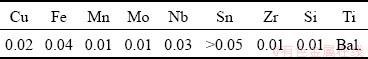
Table 2 Mechanical properties of commercially pure titanium alloy
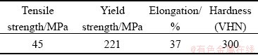
Figure 1(a) shows the sizes of sample and Figs. 1(b) and (c) show the position and friction welding performance. Figure 1(d) shows the appearances of the welded joints after welding and flash removal, respectively. Also, clip displays the friction welding process of Sample S3 (Fig. 2). The bone screw prototypes were machined using a numerically controlled machine. All the processes and testing of the bone screws were done according to the ASTM F543 standard and a product catalog of bone screws and plates (Orthomed Inc., USA) (Fig. 3).
2.2 Microstructure and composition analysis
After welding, in accordance with the ASTM E407-2017 standard, the joints were cut perpendicular to the joining interfaces so that the cross-sections could be observable. The cross- sections of welds were ground with 200-2500 grit silicon carbide papers and polished using diamond paste as the final polish. The titanium side immersed in a solution of 1 mL HF + 4 mL HCl + 95 mL H2O was etched for 40 s and the Mg alloy side immersed in a solution of 1 mL HNO3 + 20 mL acetic acid + 60 mL ethanol + 19 mL H2O was etched for 40 s. Optical microscopy (Nikon model), scanning electron microscopy (SEM), and energy dispersive spectroscopy (EDS, model FEE Quanta 200) were used to observe the welding zone microstructure. Vickers micro-hardness near the weld interface was measured by Vickers indenter under the dwelled load of 1 N for 15 s. The X-ray diffraction (XRD) test was performed by a PHILIPS PW3040 device using Cu K�� radiation with a wavelength of 1.54186 nm at an angle 2�� of 10��-90�� with a step size of 0.02�� and a time increment of 1 s.
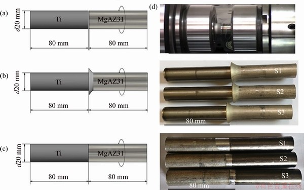
Fig. 1 Dimensions of samples (a), image of welding (b), flashes created on samples after welding process (c) and removing flashes on samples after welding process (d)
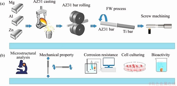
Fig. 2 Schematic diagrams of fabrication process (a) and evaluation (b)
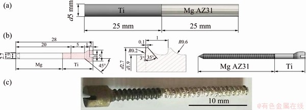
Fig. 3 Dimensions of Mg AZ31 and titanium rod samples (a), design and dimensions of screw (b), and bio-screw prototype (c)
2.3 Mechanical testing
The tensile test specimens were prepared as per the ASTM ASTM E8��2017 standard. The tensile test specimen was loaded by an INSTROM 4486 tensile testing machine. Tensile tests were carried out under the condition of 1mm/min. Since the welds are used as screws for orthopedic applications, the torsion test specimens were prepared according to the ASTM E143��2017 standard. The torsion test specimen was loaded by a BST 200 machine (Barometer Co.). Micro- hardness measurement of the welded specimens was carried out according to the ASTM E 384��2017 [25] by the Koopa MH1 micro hardness machine. The test was conducted on the samples (1 cm �� 1 cm) cross-sections with 1 cm in thickness using a load of 10 g for 10 s in the horizontal direction at 1 mm intervals.
2.4 Corrosion behavior
For electrochemical measurements, the samples with a surface area of 1 cm2 were studied by PARSTAT 2263 potentiostat/galvanostat (Princeton Applied Research). The samples were submerged in a three-electrode cell filled with Kokubo simulated body fluid (SBF) at 37 ��C with a pH value of 7.44. The electrochemical impedance spectroscopy (EIS) measurements were performed using an AC impedance system (model 2263, Princeton Applied Research) and the initial and final frequencies were set to be 105 and 10-2 Hz, respectively, with an AC sine wave amplitude of 10 mV, a frequency per decade of 10 Hz, and a delay before integration of 1 s.
2.5 Cell behavior
To assess the cell��s attachment on the sample, an MG-63 osteoblast cell line with a concentration of 2��104 cell/mL was seeded on sterilized Ti, Mg alloy, and Ti/Mg alloy weld joint and cultured for 3 d. Afterward, the cell-scaffold constructs were stained with 4��,6-diamidino-2-phenylindole, blue fluorescence in live cells (DAPI) and then subjected to fluorescence image analysis. The cell toxicity of the samples was evaluated by utilizing the MTT technique according to a previous study. The cells were seeded with a concentration of 104 cell/mL positioned separately in a 24-well plate. The cells continued to grow for various time at 37 ��C. Statistical analysis was conducted by one-way analysis of variance (ANOVA), and p<0.05 was regarded as to be significant.
3 Results and discussion
3.1 Microstructure
As shown in Fig. 1, the flash formation on the magnesium alloy side can be explained by comparing the forging temperature and flow stress of magnesium alloy and commercially pure titanium. The plastic form change is extreme and the flash formation on the magnesium alloy side is mainly due to the lower yielding strength at higher temperatures [23] and the lower forging temperature in the magnesium alloy compared with pure titanium (Fig. 3).
Since the deformation mode in friction welding is more complex compared to the rolling process, a large number of shear bands can be created in different directions. The shear bands and a number of twins created in magnesium alloys can help the grain modification process [26]. As can be seen in Fig. 4, in Samples S1, S2 and S3 the friction welded regions are divided into three areas consisting of the weld area, magnesium alloy area, and titanium area. There was no detected region and no deformation occurred on the titanium side. On the magnesium alloy side, there is a significant change in the grain size from the contact zone to the base metal and the grain size increases by increasing the distance from the joining area. In the magnesium alloy side, various regions are observed such as the weld center zone (WCZ), dynamic recrystallization zone (DRX), thermo-mechanically affected zone (TMAZ), and partially deformed zone (PDZ) [23,25,26].
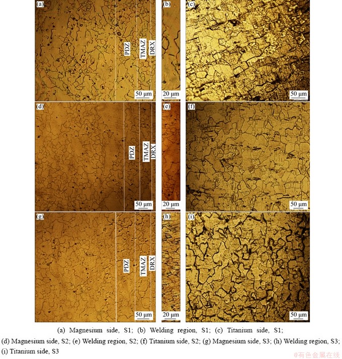
Fig. 4 Optical microscopic images
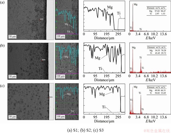
Fig. 5 Spot and line scan analysis (EDS) across interfaces around central zone
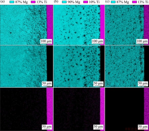
Fig. 6 EDS map analysis of Samples S1 (a), S2 (b) and S3 (c)
In the weld center or contact zone (WCZ), titanium particles are observed due to the mechanical transfer of the metal produced by the high strain rate and severe plastic deformation on the rubbing surface. The interface characteristics are not clearly evidenced in the optical and scanning electron micrographs (Figs. 4-6). However, there are recrystallized fine grain microstructures at the weld interface. The grain orientation at the contact zone becomes parallel to the weld interface due to heavy deformation.
The dynamic recrystallization area (DRX) is located next to the contact zone. This zone does not undergo rubbing action and is formed due to heavy plastic deformation at a high temperature. This usually results in the formation of a large number of dislocations. At the grain boundary of old grains, new grains are nucleated and with further deformation at the new grains the dislocation density increases. Increasing dislocation density also leads to an escalation in the substrate cellular structure, which results in the formation of recrystallized grains. Reduced recrystallization grains can be found in the shear bands that function as nucleation sites. The thermo-mechanically affected zone (TMAZ), which is exposed to lower temperatures and strains, is characterized by deformed and/or partly recrystallized grains. The partially deformed zone (PDZ) is due to less plastic deformation and lower temperatures at which the plastic forms change slightly and less strain occurs. The grains are drawn perpendicular to the axis of rotation in the TMAZ and PDZ regions. This effect is high in the TMAZ region than PDZ, which is due to the existence of this region along the interphase of common weld zone and high strain rates.
In Table 3, the grain sizes measured from different areas of the Samples S1, S2 and S3 are presented. As can be seen, Sample S3 has the smallest grain size, i.e. 8.57 ��m near the interface weld due to the optimal welding parameters (rotational speed of 1300 r/min, friction pressure of 50 MPa, forge (upset) pressure of 40 MPa, friction time of 2 s, and forge (upset) time of 8 s). The forging compression, friction time and expulsion length great influence the amount of heat input [26].
Table 3 Grain size measured for Samples S1, S2 and S3 at different areas
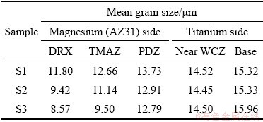
In Sample S1 (rotational speed of 1100 r/min), the grain size increases (11.80 ��m near the weld) due to the lower rotational speed and less heat input created.
The SEM images and analysis results of chemical compositions in different regions near the joining interfaces in Samples S1, S2 and S3 are shown in Fig. 5. Also, Fig. 6 shows the EDS map analysis of Samples S1, S2 and S3, respectively. It clearly shows no existence of a mixed layer at the interface with a composition between titanium and Mg alloy. The Mg and Ti elements, distribution in the axial direction of the cross section for the Mg alloy and Ti sides was determined by the EDS line scan analysis. An EDS linear scan shows that a thin non-continuous interlayer has grown in the common weld interphase, and the average thickness of this layer is approximately 250 ��m. On the Mg side, the distribution of the Mg and Ti elements has a small plateau part within several micrometers near the interfaces, implying the formation of intermetallic compounds. In contrast, only Ti was detected on the Ti side, which reconfirms that no intermetallic compounds appear on the Ti side.
In contrast to the other samples, Sample S3 has low heat input, small grain size, and high mechanical properties. After the tensile test, the tensile fracture surfaces were analyzed using X-ray diffraction analysis. The XRD pattern of the interface surface between the Mg alloy and titanium in Sample S3 (the Mg side) is shown in Fig. 7(a). The results show that the fracture surface of the Mg side contains Mg and a small amount of Ti3Al phase, and that due to the strong affinity between Ti and Al their free energy of formation is lower compared with other compounds [23]. From the Mg-Ti equilibrium diagram (Fig. 7(b)) [15] it can be inferred that the maximum solubility of titanium in magnesium is about 0.12% and the magnesium solubility in titanium is zero and, accordingly, there is no possibility for the formation of solid solutions or intermetallic compounds between titanium and magnesium [25]. However, titanium can react with aluminum in the magnesium alloy and form different intermetallic compounds such as TiAl, Ti3Al and TiAl3. It is known that plastic deformation, mechanical interlocking, and diffusion of elements occur in the rotation and forge pressure friction welding process. In the dissimilar friction welding, the strength of the joint increases with increasing the diffusion of the elements found in the base metals. Due to higher temperatures and severer deformation during friction welding, aluminum is diffused into the titanium interface because the solubility of aluminum in titanium is higher than that of magnesium in titanium, which results in the formation of a Ti3Al intermetallic compound.
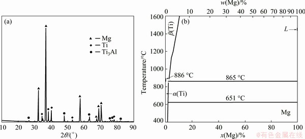
Fig. 7 XRD pattern of Sample S3 (a) and phase diagram of Mg-Ti (b) [15]
3.2 Mechanical properties
Tensile tests were carried out for the Samples S1, S2 and S3 at room temperature. For every specimen, fracture occurred at the joint interface zone in the vicinity of the intermetallic zone, which indicates that it is the weakest region. The location of the breaking of all samples was at the magnesium alloy side nearer to the interface. Table 4 shows the ultimate tensile strength and elongation of these specimens. The best tensile strength of the friction welded joint (Sample S3) was approximately 173 MPa, 71% of the Mg alloy tensile strength and 50% of the commercial titanium tensile strength. However, increasing the rotational speed not only increases the heat input, but also causes severer deformation, which ultimately makes the grains smaller. The best tensile strength result of friction welded joint (Sample S3) was found at high rotational speed, which creates more heat input and high plasticity rate. The coupled effect of severe plastic deformation (stress) and high temperature causes the diffusion depth of the alloying elements to increase from the joint interfaces to the base metals. Plastic deformation and increased temperature generate many vacancies, which could significantly induce atom diffusion during friction welding. LI et al [24] reported that the large deformation activated diffusion coefficient is about 105 higher than that activated by thermal. They also showed that the diffusion zone at the Mg-Ti interface could be augmented by increasing the rotational speed. It should be noted that the diffusion coefficient has correlations with temperature, crystal structure, and crystal defects. However, atom diffusion during friction welding is promoted not only by temperature but also by severe deformation.
The elongation of the alloy can be attributed to the differences in the elasticity and strength of the two materials. Titanium is a comparatively strong and ductile material (with 30%-40% elongation at room temperature), whereas magnesium is relatively less strong. The ductility of magnesium at room temperature is limited due to its hexagonal closely packed crystal structure which results in a limited number of active slip systems. This reflects the brittle nature of magnesium in the vicinity of the weld interface [23].
Table 4 Tensile and torsion test results of Samples S1, S2 and S3
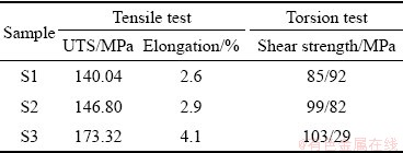
Figure 8 shows SEM images of magnesium alloy side, titanium side and Ti/Mg joint, and EDS analysis of magnesium alloy side of the fractured joint of Sample S3 (Figs. 8(d)). Magnesium alloy- titanium dissimilar friction welded joint failed at the vicinity of the intermetallic zone, indicating that it is the weakest region. As can be seen, the fractured surface showed a mixed mode of failure with the wavy nature of edges and some portions with flat deboning. This wavy nature is a discontinuous process with crack growth that creates the chevron branching pattern. The chevron shows a complex appearance in the crispy and soft cracks, and the cracks move outward from the center of the page. Since the chevron pattern of failure occurs with only plastic deformation, it is concluded that the failure of the Ti/Mg alloy friction weld is intermediate between brittle and ductile fractures. This kind of fraction results in the growth of numerous cracks with the presence of hard particles in the soft area [23,24]. The EDS analysis (Fig. 8(d)) of the fracture surface of magnesium alloy side confirms the presence of titanium particles that create multiple cracks.
The purpose of a torsion test is to determine the behavior exhibited by the screw when twisted or under torsional forces as a result of shear stress about the axis. As can be observed in Table 2, the shear strengths of Samples S1, S2 and S3 are 85.92, 99.82, and 103.29 MPa, respectively. It is obvious that the shear strength increases with increasing the rotational speed. The best ultimate shear strength is related to Sample S3 under the following friction welding conditions: rotational speed 1300 r/min, friction pressure 50 MPa, and forge pressure 40 MPa due to the amount of heat and the appropriate grains in this range. The ultimate shear strength of Sample S3 is approximately 80% of Mg alloy shear strength. The lowest shear strength is related the Sample S1 under the rotational speed of 1100 r/min. It is expected that the intensity of heat generation is proportional to the rotational speed. Increasing the heat input might increase the diffusion of the alloying elements at the joint interface and could therefore increase the shear strength of the joint. Also, there is a proportional relationship between the axial pressure and the diffusion rate. However, the rotational speed and axial pressure (friction and forge pressure) must be chosen within a reasonable range, although these two are not independent of each other. Of course, it is very important to choose the mean values of the axial pressure and rotational speed within the permissible range for a healthy weld and a small heat affected region (HAZ) [25]. The location of the breakdown of all torsion test samples was the joint interface. Figure 9(a) shows the broken Sample S3 after the torsion test.
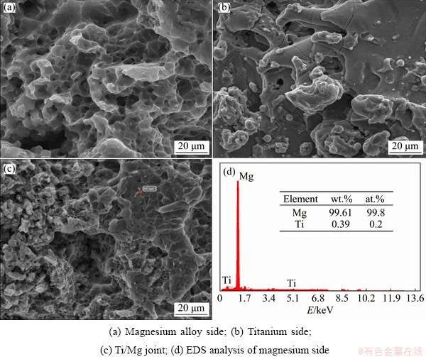
Fig. 8 SEM images of fracture surface friction welding of Sample S3
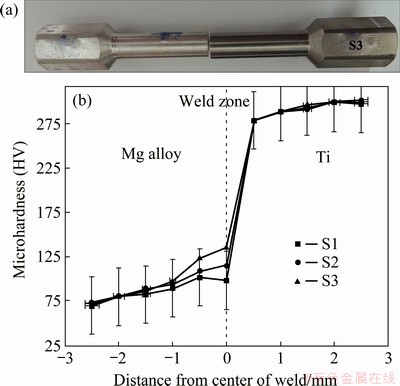
Fig. 9 Photograph of sample at rotational speed of 1300 r/min after torsion testing (a) and microhardness of Samples S1, S2 and S3 (b)
The results of microhardness test are shown in Fig. 9(b). The distribution of microhardness changes is due to microstructural changes that occur during friction welding. As can be seen, there is a steep slope in hardness from titanium to the magnesium alloy, and the hardness of the weld reaches HV 136 (Sample S3) from HV 110 (Sample S1) to for the interlayer between magnesium alloy and titanium. The hardness values from the magnesium alloy base metal to the joining point indicate an increase mainly due to grain refinement, the presence of intermetallic phases (Ti3Al), and the titanium phase. However, no such change in hardness was observed in the titanium side due to the restricted deformation of titanium compared to the magnesium alloy during friction welding [23]. Due to the highest tensile and shear strengths and hardness of the Ti/Mg alloy dissimilar friction welding with rotational speed of 1300 r/min among all specimens, this sample was selected for the electrochemical measurements and cellular assay.
3.3 Corrosion behavior
Figure 10(a) exhibits the potentiodynamic polarization (PDP) curves of Ti, Mg alloy, and Ti/Mg alloy weld joint (zone with size of 5 mm �� 5 mm) in SBF at 37 ��C. The PDP curves indicate that the Ti side shows more significant corrosion potential in comparison with the Mg alloy side and the Ti/Mg alloy weld joint side. However, it is worth noting that the Mg alloy and Ti/Mg alloy weld joint presented lower potential gap than the Ti and Ti/Mg alloy weld joint.
Since the potential gap represents a driving force for the occurrence of galvanic corrosion reactions, promoting the reactions between anodic and cathodic through conveying electrons from the side of the anode to cathode will accelerate the driving force, and subsequently escalates the potential gaps. Likewise, the Ti side presented lower corrosion current density (Jcorr) compared with the other two sides (Mg and Ti/Mg weld joint). Hence, the corrosion resistance of Ti is higher in comparison with that of the other two sides (Mg and Ti/Mg weld joint). The results also show that the Ti and Mg alloy sides demonstrate lower Jcorr in comparison with the Ti/Mg weld joint side, owing to the occurrence of galvanic corrosion. Galvanic corrosion is generally considered to be the main reason for high corrosion rate of the Ti/Mg weld joint side. In this context, the formation of a galvanic cell couple between Ti and Mg alloy in the Ti/Mg weld joint side resulted in increasing the corrosion process of Mg when Mg is in contact with another, nobler metal such as Ti with a large corrosion potential difference. In the present study, Ti and Mg alloy are considered as a cathode and an anode, respectively. When a weld joint side is exposed to the SBF solution, the corrosion rate of Mg alloy increases and hence the joint is significantly corroded. The Nyquist pattern (Fig. 10(b)) demonstrates the typical semicircle loop having different radii where the Ti side displays higher charge transfer resistance (Rct) (53 ����cm2) compared with the Mg alloy (32 ����cm2) and the Ti/Mg weld joint sides (45 ����cm2). Moreover, the greater Rct value implies greater corrosion resistance of the alloy part (the Ti side). The simple equation is employed to characterize the samples. In Fig. 10(b) Rs is the solution resistance, Cf denotes the coating capacitance, Rf represents the film resistance, Cdl denotes the electric double-layer capacitance of the passive film, RL is the inductive resistance and L represents the inductance. RL and L point out the presence of metastable Mg ion throughout the dissolution of Mg alloy substrate (the low frequency inductance loop). Additionally, the Bode magnitude plot further confirms that the Ti side exhibits the highest corrosion resistance followed by Mg and Ti/Mg weld joint sides since the highest value of the modulus (|Z|) is related to the Ti side (Fig. 10(c)). However, the joining of Ti to the Mg alloy leads to a decrease in the modulus value. Similarly, the result of Bode phase angle shows that the highest phase angle is related to Ti (-13.2��) and Mg alloy (-5.8��) sides while the Ti/Mg weld joint side presents the lowest phase angle (-3.9��), as can be seen in Fig. 10(d). These results demonstrate that the Ti/Mg weld joint might present a slightly higher corrosion rate but this rate meets the requirements for implant application [27-30].
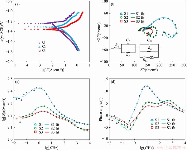
Fig. 10 Potentiodynamic polarization curves (a), Nyquist plot (b), Bode magnitude plot (c) and Bode phase plot (d) of Samples S1 (Ti side), S2 (Mg side) and S3 (Ti/Mg weld joint)
3.4 In vitro cytotoxicity and cell proliferation
The fluorescence image also exhibits the results of cell attachment on the Ti, Mg alloy, and Ti/Mg weld joint specimens (zone with a size of 5 mm �� 5 mm) after 3 days (Fig. 11). The result shows that the MG-63 cells have greater interaction with Ti and Mg alloy sides compared to the Ti/Mg weld joint side. In this respect, greater cell attachment and density were found on the Ti and Mg alloy sides compared to the Ti/Mg weld joint side, which is attributed to the higher corrosion rate of the joint side and subsequent formation of corrosion products on its surface. For further confirmation of the results, the MG-63 cell cytotoxicity and proliferation were assessed via the MTT assay. The cytotoxicity test provides essential data for easily finding the biocompatibility of Ti, Mg alloy and the Ti/Mg weld joint. After culturing the medium with Ti, Mg alloy and Ti/Mg weld joint for different incubation time, lower cell viability was observed for the Ti/Mg weld joint, whereas both Ti and Mg alloy showed higher viability (Fig. 11(g)). There is no difference between the Ti and Mg alloy sides in terms of cell viability. Similarly, the viability of the cells on the Ti, Mg alloy and Ti/Mg weld joint slightly increased with the escalation of the incubation time, implying that they were cyto-compatible. Lower viability of the Ti/Mg weld joint is attributed to the relatively higher corrosion rate of the joint part than the other parts (Ti and Mg alloy). Higher corrosion rate leads to more release of the Mg2+ ions (Mg��Mg2++2e, anodic reaction) and H2 (2H2O+ 2e��H2+2OH-, cathodic reaction), which could affect the cell performance and reduce the MG-63 cell proliferation. However, increasing the culture time resulted in more recovery of the cell viability as a result of cellular adaptations [11,31-38].
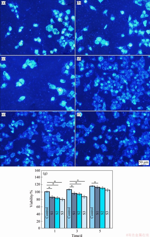
Fig. 11 DAPI staining of MG-63 osteoblasts cells on Samples S1 (Ti side) (a, d), S2 (Mg side) (b, e) and S3 (Ti/Mg weld joint) (c, f) after incubation for 24 and 120 h and cell viability of MG-63 osteoblast cells cultured for various time on Samples S1 (Ti side), S2 (Mg side) and S3 (Ti/Mg weld joint) (g) (p<0.05)
4 Conclusions
(1) Microstructural study of the friction welding of dissimilar titanium-magnesium alloy shows that the magnesium alloy side consisted of four regions, including the weld center zone (WCZ), dynamic recrystallization zone (DRX), thermo-mechanically affected zone (TMAZ) and partially deformed zone (PDZ) while no deformation occurred in the titanium side.
(2) The highest tensile and shear strengths were 173 and 103.2 MPa, respectively, under the friction welding conditions of 1300 r/min rotational speed, 50 MPa friction pressure, and 40 MPa forging pressure. The friction welded Ti/Mg alloy joint failed in the vicinity of the intermetallic zone, which indicates that it is the weakest region. Also, the hardness values from the magnesium alloy base metal to the joining point indicate an increase mainly due to grain refinement, Ti3Al phase and titanium particles.
(3) SEM, EDS, and XRD analyses of the fracture surface of the Mg side confirmed the intermediate between brittle and ductile fracture, the presence of Ti3Al intermetallic phase, and the presence of titanium particles at the joint interface.
(4) Corrosion behavior of the Ti/Mg alloy joint was observed to be better compared to Ti and Mg alloy from the immersion studies. Galvanic corrosion was found to be the main mechanism behind higher corrosion rates of the weld joint. Moreover, the result of the MTT assay with MG-63 cells presented lower cell viability for the Ti/Mg weld joint compared with both Ti and Mg alloy.
Acknowledgments
The authors would like to acknowledge Islamic Azad University, Najafabad Branch for providing the research facilities.
References
[1] ZHENG Y F, GU N X, WITTE F. Biodegradable metals [J]. Materials Science and Engineering R, 2014, 77: 1-34.
[2] LI N, ZHENG Y. Novel magnesium alloys developed for biomedical application: A review [J]. Journal of Materials Science & Technology, 2013, 29: 489-502.
[3] KHORASANI A M, GOLDBERG M, DOEVEN H E, LITTLEFAIR G. Titanium in biomedical applications properties and fabrication: A review [J]. Journal of Biomaterials and Tissue Engineering, 2006, 5: 593-619.
[4] ZHENG Y F, GU X N, XI Y L, CHAI D L. In vitro degradation and cytotoxicity of Mg/Ca composites produced by powder metallurgy [J]. Acta Biomaterialia, 2010, 6: 1783-1791.
[5] GU N X, ZHENG F Y. A review on magnesium alloys as biodegradable materials [J]. Frontiers of Materials Science in China, 2010, 4: 111-115.
[6] OAK J J, INOUE A. Formation, mechanical properties and corrosion resistance of Ti-Pd base glassy alloys [J]. Non- Crystalline Solids, 2008, 354(17): 1828-1832.
[7] KUMAR K, GILL R, BATRA U. Challenges and opportunities for biodegradable magnesium alloy implants [J]. Materials Technology, 2018, 2: 153-172.
[8] TIAN Q H, DENG D, LI Y, GUO X Y. Preparation of ultrafine silver powders with controllable size and morphology [J]. Transactions of Nonferrous Metals Society of China, 2018, 28: 524-533.
[9] CUI Y, XU J, LU N, ZENG R C, ZOU H Y, LI Q S, ZHANG F. In vitro corrosion resistance and antibacterial properties of layer-by-layer assembled chitosan/poly-L-glutamic acid coating on AZ31 magnesium alloys [J]. Transactions of Nonferrous Metals Society of China, 2017, 27: 1081-1086.
[10] LI M, REN L, LI L, HE P, LAN G, ZHANG Y, YANG K. Cytotoxic effect on osteosarcoma MG-63 cells by degradation of magnesium [J]. Journal of Materials Science & Technology, 2014, 30(9): 888-893.
[11] MUTLU I. Production and fluoride treatment of Mg-Ca-Zn-Co alloy foam for tissue engineering applications [J]. Transactions of Nonferrous Metals Society of China, 2018, 28: 114-124.
[12] BUZOLIN H R, MOHEDANO M, MENDIS C L, MINGO B, TOLNAI D, BLAWERT C, KAINER K U, PINTO H, HORT N. Corrosion behavior of as-cast ZK40 with CaO and Y additions [J]. Transactions of Nonferrous Metals Society of China, 2018, 28: 427-439.
[13] POINERN E G, BRUNDAVANAM S, FAWCETT D. Biomedical magnesium alloys: a review of material properties, surface modifications and potential as a biodegradable orthopaedic implant [J]. Biomedical Engineering, 2012, 2: 218-240.
[14] CHEN Q Z, THOUAS A G. Metallic implant biomaterials [J]. Materials Science and Engineering R, 2015, 87: 1-57.
[15] MURRAY J L. The Mg-Ti (magnesium-titanium) system [J]. Bulletin of Alloy Phase Diagrams, 1986, 7: 245-248.
[16] SONG Y, SHAN D, CHEN R, ZHANG F, HAN E H. Biodegradable behaviors of AZ31 magnesium alloy in simulated body fluid [J]. Materials Science and Engineering C, 2009, 29: 1039-1045.
[17] TRIVEDI P, MISRA R D K. Surface biodegradation behavior of rare earth- containing magnesium alloys with different microstructure: The impact on apatite coating formation on the surface [J]. Materials Technology, 2018, 33: 488-494.
[18] TRIVEDI P, NUNE K C, MISRA R D K. Grain structure dependent self-assembled bioactive coating on Mg-2Zn-2Gd alloy: Mechanism of degradation at bio interfaces [J]. Surface and Coatings Technology, 2017, 315: 250-257.
[19] TRIVEDI P, NUNE K C, MISRA R D K, GOEL S, JAYGANTHAN R, SRINIVASAN A. Grain refinement to submicron regime in multiaxial forged Mg-2Zn-2Gd alloy and relationship to mechanical properties [J]. Materials Science and Engineering A, 2016, 668: 59-65.
[20] LI S, CUI T, HAO Y, YANG R. Fatigue properties of a metastable beta-type titanium alloy with reversible phase transformation [J]. Acta Biomaterialia, 2008, 4: 305-317.
[21] NASUTION A, MURNI N, SING N, IDRIS M, HERMAWAN H. Partially degradable friction-welded pure iron�Cstainless steel 316L bone pin [J]. Journal of Biomedical Materials Research (Part B): Applied Biomaterials, 2015, 1: 31-38.
[22] NASUTION A, ULUM M F, KADIR M R A, HERMAWAN H. Mechanical and corrosion properties of partially degradable bone screws made of pure iron and stainless steel 316L by friction welding [J]. Science China Materials, 2018, 61: 593-606.
[23] LAKSHMINARAYANAN A, SARANARAYANAN R, SRINIVAS V K, VENKAT-RAMAN B. Characteristics of friction welded AZ31B magnesium�Ccommercial pure titanium dissimilar joints [J]. Journal of Magnesium and Alloys, 2015, 3(3): 315-321
[24] LI R D, LONG L J, TAO X J, SHENG Z F, KE Z, ZHONG J C. Friction heat production and atom diffusion behaviors during Mg-Ti rotating friction welding process [J]. Transactions of Nonferrous Metals Society of China, 2012, 22: 2665-2671.
[25] LI W, VAIRIS A, PREUSS M, MA T. Linear and rotary friction welding review [J]. International Materials Reviews, 2016, 61(2): 1-30.
[26] FUKUMOTO S, TANAKA S, ONO T, TSUBAKINO H, TOMITA T, ARITOSHI M, OKITA K. Microstructural development in friction welded AZ31 magnesium alloy [J]. Materials Transactions, 2006, 47(4): 1071-1076.
[27] WITTE F, KAESE V, HAFERKAMP H, SWITZER E, LINDENBERG A, WIRTH C J, WINDHAGEN H. In vivo corrosion of four magnesium alloys and the associated bone response [J]. Biomaterials, 2005, 17: 3557-3563.
[28] GAO Y, YEROKHIN A, MATTHEWS A. DC plasma electrolytic oxidation of biodegradable cp-Mg: In-vitro corrosion studies [J]. Surface and Coatings Technology, 2013, 234: 132-142.
[29] BAKHSHESHI RAD H R, HAMZAH E, KADIR M R A, SAUD S N, KASIRI-ASGARANI M, KAHRIZSANGI R E. The mechanical properties and corrosion behavior of double-layered nano hydroxyapatite-polymer coating on Mg-Ca alloy [J]. Journal of Materials Engineering and Performance, 2015: 4010-4021.
[30] GAO Y, YEROKHIN A, PARFENOV E, MATTHEWS A. Application of voltage pulse transient analysis during plasma electrolytic oxidation for assessment of characteristics and corrosion behavior of Ca- and P-containing coatings on magnesium [J]. Electrochimica Acta, 2014, 149: 218-230.
[31] WAIZY H, SEITZ J M, REIFENRATH J, WEIZBAUER A, BACH F W, LINDENBERG A M, DENKENA B, WINDHAGEN H. Biodegradable magnesium implants for orthopedic applications [J]. Journal of Materials Science, 2013, 48: 39-50.
[32] MUGADA K K, ADEPU K. Effect of knurling shoulder design with polygonal pins on material flow and mechanical properties during friction stir welding of Al-Mg-Si alloy [J]. Transactions of Nonferrous Metals Society of China, 2019, 29: 2281-2289.
[33] CHENG Yuan-fen, DU Wen-bo, LIU Ke, FU Jun-jian, WANG Zhao-hui, LI Shu-bo, FU Jin-long. Mechanical properties and corrosion behaviors of Mg-4Zn-0.2Mn- 0.2Ca alloy after long term in vitro degradation [J]. Transactions of Nonferrous Metals Society of China, 2020, 30: 363-372.
[34] AMIRNEJAD M, RAJABI M, MOTAVALLI A. Effect of addition of Si on microstructure, mechanical properties, bio-corrosion and cytotoxicity of Mg-6Al-1Zn alloy [J]. Transactions of Nonferrous Metals Society of China, 2018, 28: 1755-1762.
[35] WANG Li-qing, QIN Gao-wu, SUN Shi-neng, REN Yu-ping, LI Song. Effect of solid solution treatment on in vitro degradation rate of as-extruded Mg-Zn-Ag alloys [J]. Transactions of Nonferrous Metals Society of China, 2017, 27: 2607-2612.
[36] DOOST MOHAMMADI F, JAFARI H. Microstructure characterization and effect of extrusion temperature on biodegradation behavior of Mg-5Zn-1Y-xCa alloy [J]. Transactions of Nonferrous Metals Society of China, 2018, 28: 2199-2213.
[37] YU Song, WANG Xiao-hu, CHEN Yi-gang, ZHENG Qi, ZHANG Xiao-nong, ZHAO Chang-li, ZHANG Shao-xiang, YAN Jun. In vitro and in vivo evaluation of effects of Mg�C6Zn alloy on tight junction of intestinal epithelial cell [J]. Transactions of Nonferrous Metals Society of China, 2015, 25: 3760-3766.
[38] ZHANG Wan-peng, MA Ming-long, YUAN Jia-wei, SHI Guo-liang, LI Yong-jun, LI Xing-gang, ZHANG Kui. Microstructure and thermophysical properties of Mg-2Zn-xCu alloys [J]. Transactions of Nonferrous Metals Society of China, 2020, 30: 1803-1815.
Mojtaba Sadeghi GOGHERI, Masoud KASIRI-ASGARANI, Hamid Reza BAKHSHESHI-RAD, Hamid GHAYOUR, Mahdi RAFIEI
Advanced Materials Research Center, Department of Materials Engineering,Najafabad Branch, Islamic Azad University, Najafabad, Iran
ժ Ҫ����ת��Ϊ1100��1200 ��1300 r/min�����£�ͨ����תĦ����������ɽ���þ�Ͻ�����ҵ�������ֺ��Ӻ�ӹ����ݶ����о����ֽ�ͷ�����ܡ�����������������/þ�Ͻ��ͷ�����ӽϺá���þ�Ͻ�һ��۲쵽����������(WCZ)����̬�ٽᾧ��(DRX)������Ӱ����(TMAZ)�;ֲ�������(PDZ)����1300 r/minת�����Ʊ����ݶ�������ߵ�����ǿ�Ⱥͼ���ǿ�ȣ��ֱ�Ϊ173��103.2 MPa����/þ�Ͻ�����Ħ������ͷ�ں���Ti3Al�Ľ����仯����������ʧЧ�����ھ���ϸ��(8.57 ��m)���ѿ�����Ӱ�죬��þ�Ͻ�һ�ൽ��������Ӳ��ֵ��������һ���Ӳ��ֵ���ֲ��䡣����ʵ����ʾ��/þ�Ͻ��ͷ�ĸ�ʴ���ʸ��ڴ�����þ�Ͻ�ĸ�ʴ���ʡ����⣬1300 r/min ת�����Ʊ��Ľ�ͷ��������õ���ʴ���ܣ���ʾ�����õ����������Ժ�ϸ������(98.12%)��
�ؼ��ʣ�þ�Ͻ���ҵ���ѣ�Ħ����������ǿ�ȣ����オ����
(Edited by Xiang-qun LI)
Corresponding author: Masound KASIRI-ASGARANI, E-mail: m.kasiri.a@gmail.com;
Hamid Reza BAKHSHESHI-RAD, E-mail: rezabakhsheshi@gmail.com, rezabakhsheshi@pmt.iaun.ac.ir
DOI: 10.1016/S1003-6326(20)65434-6

