�����ٻ�����Ϳ�뼤������Al0.2CrFeNi(Co, Cu)�Ͻ�ĸɻ���ĥ���������ܶԱ��о�
��Դ�ڿ����й���ɫ����ѧ��(Ӣ�İ�)2021���8��
�������ߣ�Azmi ERDOGAN Kadir Mert DOLEKER
����ҳ�룺2428 - 2441
�ؼ��ʣ����غϽ𣻼������ۣ������ٻ�����Ϳ(HVOF)��ĥ������
Key words��high entropy alloy; laser re-melting; HVOF; wear; oxidation
ժ Ҫ���ó����ٻ�����Ϳ(HVOF)����316L����ֻ����ϳ���Al0.2CrFeNiCo��Al0.2CrFeNiCu���ָ��غϽ�Ϳ�㣬Ȼ���Ϳ����м�������(LR)�Ը���������֯���о�LR���ն�Ϳ��ɻ���ĥ���������Ϊ��Ӱ�졣�������������ĩ�뵥��Ԫ�ػ�ϵ���HVOFͿ�����γ��������LR����������������ס�LR�����ֺϽ��о���FCC��Ϊ��������Al0.2CrFeNiCo�Ͻ��й۲쵽BCC��sigma��Cr2O3�ࡣHVOF��Al0.2CrFeNiCo�� Al0.2CrFeNiCu Ϳ���Ӳ�ȷֱ�ΪHV 591��HV 361��LR����Ӳ�ȷֱ��С��HV 259��HV 270����������Ʒ��ȣ���ȻHVOFͿ�����غ����ӵ�Ӱ���������ֳ���ߵ���ĥ�ԣ��һ������ĥ��������ʵ���HVOFͿ�㱻��ȫ����������50 h��Ϳ�������ṹ�ӻ��������䡣LRͿ����нϺõĿ��������ܡ�����ʵ���Al0.2CrFeNiCoͿ����Ҫ��Cr2O3��������ɣ�Cr2O3������������ʵ����ڵ������ٶȽ�������Al0.2CrFeNiCuͿ������Ҫ�ɼ⾧ʯ����ɡ�
Abstract: Al0.2CrFeNiCo and Al0.2CrFeNiCu high entropy alloys were deposited with high velocity oxygen fuel (HVOF) on 316L substrate. Later, a laser re-melting (LR) process was applied to enhancing the coating microstructure. LR process effects on dry sliding wear and oxidation behaviors were investigated. The mixture of powders with free elements led to the formation of inner oxides in HVOF coatings. The oxide and porosity were eliminated using LR. After LR, FCC was the dominant phase in both alloys, while BCC, sigma and Cr2O3 phases were observed in Al0.2CrFeNiCo alloy. The hardnesses of the Al0.2CrFeNiCo and Al0.2CrFeNiCu coatings after HVOF were HV 591 and HV 361, respectively. After LR, the hardnesses decreased to HV 259 and HV 270, respectively. Although HVOF coatings were most affected by increased load, they showed the highest wear resistance compared to other samples. The lowest wear resistance could be seen in the substrate. After the oxidation tests, HVOF coating layer was completely oxidized and also, the coating layer was delaminated from the substrate after 50 h oxidation due to its porous structure. LR coatings exhibited better oxidation performance. Al0.2CrFeNiCo was dominantly composed of Cr2O3, exhibiting a slower-growing tendency at the end of the oxidation tests, while Al0.2CrFeNiCu was composed of spinel phases.
Trans. Nonferrous Met. Soc. China 31(2021) 2428-2441
Azmi ERDOGAN1, Kadir Mert DOLEKER2
1. Department of Metallurgy and Materials Engineering, Faculty of Engineering Architecture and Design, Bartin University, Bartin, Turkey;
2. Department of Metallurgy and Materials Engineering, Faculty of Engineering, Ondokuz Mayis University, Samsun, Turkey
Received 7 August 2020; accepted 26 June 2021
Abstract: Al0.2CrFeNiCo and Al0.2CrFeNiCu high entropy alloys were deposited with high velocity oxygen fuel (HVOF) on 316L substrate. Later, a laser re-melting (LR) process was applied to enhancing the coating microstructure. LR process effects on dry sliding wear and oxidation behaviors were investigated. The mixture of powders with free elements led to the formation of inner oxides in HVOF coatings. The oxide and porosity were eliminated using LR. After LR, FCC was the dominant phase in both alloys, while BCC, sigma and Cr2O3 phases were observed in Al0.2CrFeNiCo alloy. The hardnesses of the Al0.2CrFeNiCo and Al0.2CrFeNiCu coatings after HVOF were HV 591 and HV 361, respectively. After LR, the hardnesses decreased to HV 259 and HV 270, respectively. Although HVOF coatings were most affected by increased load, they showed the highest wear resistance compared to other samples. The lowest wear resistance could be seen in the substrate. After the oxidation tests, HVOF coating layer was completely oxidized and also, the coating layer was delaminated from the substrate after 50 h oxidation due to its porous structure. LR coatings exhibited better oxidation performance. Al0.2CrFeNiCo was dominantly composed of Cr2O3, exhibiting a slower-growing tendency at the end of the oxidation tests, while Al0.2CrFeNiCu was composed of spinel phases.
Key words: high entropy alloy; laser re-melting; HVOF; wear; oxidation
1 Introduction
Multi-component alloys, also known as high entropy alloys (HEAs), are a new type of material with very high potential for many structural applications [1,2]. These alloys are built on more than 4 principle alloying elements rather than a single principle element [3,4]. For this reason, many properties that are difficult to obtain in conventional alloys can be obtained simultaneously in these alloys [5]. Since HEAs were introduced by YEH et al [6] in 2004, they have attracted considerable attention due to their superior mechanical properties, high temperature performance and corrosion resistance. In the production of bulk HEAs, arc melting and powder metallurgy methods are commonly used [7-9]. Also, in recent years, research on HEA coatings has been increasing rapidly. In most studies, although most of the HEA coatings are prepared by laser coating [10-12], a limited number of HVOF coatings [13,14] have also been investigated.
Thermal spray coatings are widely used to enhance the surface properties of metallic materials. There are various types of coating techniques such as plasma spraying, high-velocity oxygen fuel (HVOF), cold spraying, flame spraying, and low-pressure plasma spraying in thermal spray coatings [15,16]. In metallic coating production, plasma spraying can cause the oxide and porosity contents in the coating structure due to spraying with the low speed at high temperature. That��s why higher speed and lower spraying temperature are important to get a dense coating with low oxide content coating [17]. HVOF coating technique provides high powder velocity and relatively low spraying temperature, thus metallic coatings are commonly produced by this technique [18]. Surface re-melting is a very popular technique for surface modification in coatings. Generally, laser re-melting, tungsten inert gas re-melting or electron beam re-melting process is used to re-melt the surface of the coatings [19-22]. Laser re-melting is the most preferred re-melting technique due to its high speed, practical control and relatively low cost [23,24]. Laser beam forms a local melt pool scanning the surface of materials [25]. The formed melt pool provides a denser surface. Besides, a high cooling rate after the re-melting refines the grains and homogenizes the microstructure. Thus, the microstructure of thermal spray coating can be easily enhanced.
Under high temperature service conditions, oxidation can give severe damage to metallic materials. With the effect of high temperature, materials can form their oxides which may impair their high temperature resistance. This can cause a high mass lose in materials [26]. Therefore, protective oxide former alloys on their surface such as Al2O3, Cr2O3 or SiO2 are preferred in high temperature applications [27]. Alloys with Al, Cr and Si contents, intermetallics, MCrAlY alloys or high entropy alloys can be used to form a protective oxide scale on the surface of materials. In this study, Al0.2CrFeNiCo and Al0.2CrFeNiCu alloys were sprayed using HVOF technique on a 316L stainless steel substrate and were re-melted by laser to get dense and homogeneous microstructure. The produced coatings and substrate were exposed to dry sliding wear and high temperature oxidation tests. The obtained results were comparatively investigated in comparison with each other and literature findings.
2 Experimental
Al, Cr, Fe, Ni, Co and Cu powders (Alfa Aesar, average grain size <44 ��m, purity >99%) were mechanically mixed for 1 h as Al0.2CrFeNiCu and Al0.2CrFeNiCo (at.%). The prepared powders were sprayed on commercially received 316 L stainless steel (S.S.) using the HVOF (Oerlikon Metco WokaStar-610-Sz) technique. The coatings were also subjected to laser remelting (Alpha Laser, Al-200) process as one pass above the coating layer. The spraying and re-melting parameters of coatings are given in Table 1.
The prepared HVOF and laser re-melted (LR) coatings were investigated by scanning electron microscopy (SEM) (Tescan, MAIA3 XMU) and elemental mapping spectroscopy. X-ray diffractometer (XRD) (Rigaku Dmax 2200 PC, Cu K�� radiation) analysis was applied to identifying the phase information and formed oxide phases in the samples.
Wear tests were carried out with a ball-on-disc tribometer wear tester in dry sliding conditions. Tests were performed out against a WC ball (6 mm in diameter) at room temperature under loads of 5, 10, and 15 N. Sliding speed of 5.4 cm/s was used in the reciprocating test procedure. The total sliding distance was determined as 100 m and the wear traces were made on a 5 mm linear path. Wear tests were repeated 3 times for reliability. The volume losses were calculated by measuring the traces from at least 5 different points. Microhardness measurements were carried out on a QNESS Q10 instrument (Austria) with a load of 100 g and a dwell time of 15 s.
Isothermal oxidation tests were carried out on 316L S.S., HVOF and laser re-melted coatings at 900 ��C for 5, 25, 50 and 125 h in an electric furnace (PLF 130/12, Turkey). The formed oxide thickness was measured using Image Pro Plus 6 software program. The average oxide thickness of laser melted coatings was calculated by 10 measurements taking 5 different images.
Table 1 Spraying and re-melting parameters of coating
3 Results and discussion
3.1 Microstructure
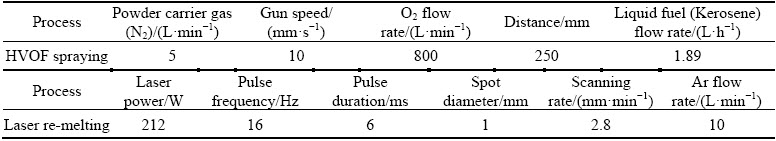
In Fig. 1, SEM images belonging to as-sprayed HVOF Al0.2CrFeNiCu and Al0.2CrFeNiCo coatings are given. The coating thickness is 70-90 ��m for both coatings. Lamellar structured coatings have oxide contents due to use of free element mixture. Especially, the presence of free Al causes the formation of embedded alumina phases during the flight of particles. In the deposition of coatings, parameter optimization was not done. Normally, HVOF coatings do not contain high level oxide in the deposition of alloys. In the coating, dark regions represent oxide structure. Porosity contents are low level for each coating. Due to the presence of free elements, phase formation or reaction between elements is not seen. One of the aims of the study was to improve the coatings by laser melting by reducing powders loss, no optimization especially was made in coating production. That��s why the coating has unmelted particles and porous structure.
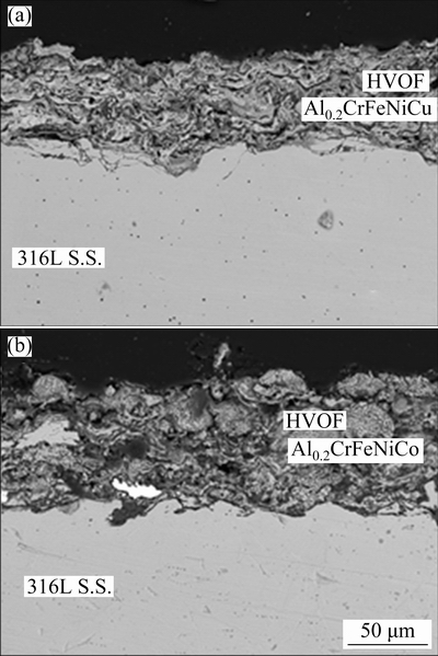
Fig. 1 SEM images of HVOF sprayed Al0.2CrFeNiCu (a) and Al0.2CrFeNiCo (b) coatings
These were eliminated by laser melting in the current study. Compact powder mixtures formed phase with the remelting.
In Fig. 2, XRD analysis result belonging to laser re-melted coatings was given. It can be seen that the FCC (FeNi) phase was the dominant phase in the laser re-melted coatings. The higher intensity values of the FCC diffraction peaks indicate that this phase was the more dominant phase in the microstructure [7,28]. However, BCC (FeCr), sigma and Cr2O3 secondary phases identified from weaker peaks were seen in the Al0.2CrFeNiCo alloy. Volumetrically smaller amounts of phases can be expected to give weaker peaks. For this reason, when assigning the phases, particular attention was paid to ensuring that the assigned phase corresponds to the strongest peak of that phase��s card and the results are consistent with those of similar studies. In XRD peak intensities, a similar tendency was seen in direct laser deposited Al0.3CrFeNiCo HEA as well [29]. Normally, the strongest peak was seen at smaller 2�� in CoCrFeNi-based HEAs with the same composition [30,31]. There was no phase transformation after the laser remelting yet the relative intensities of peaks changed. The same effect was also observed in 316L steel after the production with selective laser melting technique depending on building direction [32]. The change in building direction during the production caused preferential orientation. This was observed as different relative intensities in XRD analysis. Similarly, it is thought that laser melting can cause the changing orientations of grains due to the rapid heating and cooling effect. Microsegregation of some phases during the solidification can attribute to the change in the peak density. Besides preferred growth direction, especially in cubic materials, may be shown as another reason [33,34]. Especially, the high cooling after laser remelting led to preferential growth of grains. In fast solidified casting samples, the same effect is also seen as the formation of dendrite and columnar microstructures [35]. Accordingly, the strongest peak was identified at 2�� of 50.9�� in both re-melted coatings. This situation is supported by the microstructure images given in Fig. 3. It is seen that there is an orientation in the grains in both alloys, being more prominent in Al0.2CrFeNiCo alloy.
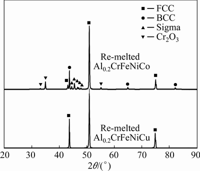
Fig. 2 XRD patterns of laser re-melted Al0.2CrFeNiCu and Al0.2CrFeNiCo coatings
Fig. 3 SEM images of laser re-melted HEAs
SEM images of Al0.2CrFeNiCo and Al0.2CrFeNiCu coatings after laser re-melting are given in Fig. 3. Compared to HVOF, the coatings exhibited a much more homogeneous and lower porosity structure. In addition, the laser re-melting process provided a better bonding of the coating layer to the substrate. No porosity structure was observed at the coating-substrate interface. A single-phase microstructure occurred in both coatings after laser re-melting. At this point, a two-phase microstructure can be expected in high entropy alloys produced at relatively slow cooling rates [5,36,37]. It has been explained in many studies that the ��mixing enthalpy�� values between elements are effective in phase formation in high entropy alloys [38-40]. In alloys similar to the AlCrFeNiCo alloy system, 2 or 3 phase microstructures have been observed depending on the mixing enthalpy and amount of the elements. In alloys similar to the AlCrFeNiCu alloy system, especially Cu was isolated with other elements due to relatively positive mixing enthalpy values [41]. However, these situations apply mostly to relatively lower cooling rates. It is possible to talk about very high cooling rates in laser re-melting. We can say that the entropy effect, which is one of the 4 core effects of high entropy alloys, was evident here [12,42]. In high entropy alloys, the entropy effect predominates at higher temperatures, which reduces the number of phases. The low number of phases at high temperatures can be protected even at room temperature thanks to their high cooling rate. Al0.2CrFeNiCu alloy has mostly coaxial grains after laser re-melting, while Al0.2CrFeNiCo alloys mostly have grains oriented towards the surface.
3.2 Dry sliding wear behavior
Volume losses occurred in dry sliding tests of the coatings and the substrate under different loads are given in Fig. 4(a). Volume losses increased in all samples due to the increase in the load. With the increase of the applied load, the ball tip creates more effect on the opposite surface [43]. Therefore, material separation from the opposite surface becomes easier and volume loss increases. However, when viewed proportionally in terms of the load, volume loss increased slightly in some samples, while it increased more in others. The load had a higher effect on volume loss in HVOF coatings compared to other materials. In HVOF coatings, very low volume losses under 5 N load increased more when the load increased to 15 N compared to other coating and substrate. In this case, it can be said that HVOF coatings are more sensitive to load. It is possible to attribute this to the brittle behavior of HVOF coatings due to their porous and oxidized nature. Due to their porous and brittle structure, the increased load facilitated material separation. Although HVOF coatings were most affected by the increased load, they showed much lower volume losses compared to other samples. It is possible to explain this primarily by the surface hardness of the samples. Its higher hardness compared to other samples has reduced wear loss. Average surface hardnesses of 316L, HVOF-Co, HVOF-Cu, RL-Co and Cu samples were HV 186, HV 591, HV 361, HV 259 and HV 270, respectively. Considering the volume loss, it is possible to say that the hardness is directly effective. It is possible to say that samples with high hardness are more resistant to wear [44]. Untreated 316L S.S. with the lowest hardness showed the highest wear loss. However, it is not possible to explain the fact that HVOF coatings show such low wear loss despite their porous and brittle structure with just the hardness. The increase in hardness or brittleness only negatively affects the wear loss under extreme load. It is not possible to talk about an overload here. The fact that HVOF coatings have oxide compounds with ceramic structure ensured their high hardness. This contributed to the wear resistance. In addition, when the friction coefficients are examined, it is seen that the friction coefficients of these samples were low. The oxide compounds on the surface also reduced the friction coefficient. This explains the low volume loss seen in HVOF samples together with the hardness.
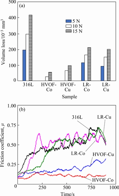
Fig. 4 Volume loss values of samples (a), and friction coefficient curves for samples performed under 5 N load (b)
In Fig. 4(b), the friction coefficient curves occurred under 5 N load in all samples are given. Considering the friction coefficient curves, it is seen that HVOF coatings show considerably lower values compared to the other samples. The low resistance of HVOF coatings against friction keeps the friction coefficient low. This is an important factor in keeping the volume loss of these coatings low, together with hardness. At this point, the low friction coefficient of these coatings can be attributed to their oxidized structure. Oxide layers existing on the surface or formed during wear can contribute to reducing the volume loss [45]. Because the oxide layer has a ceramic structure, it generally has a higher hardness than the main material [46]. This contributes to the wear resistance of the oxides. In addition, the ability to hold each other between the abrasive ball and the opposing surface is reduced by oxides. Therefore, it acts as a lubricant between the ball tip and the counter material [47]. This decreases the friction coefficient and increases the resistance of the opposite surface. For the reasons listed, HVOF coatings have high wear resistance and low volume loss.
SEM images of the wear traces occurring after the tests performed under 15 N load of all samples are given in Fig. 5. The wear traces occurring in the tests confirm both the volume loss and the friction coefficient. The adhesion-related ruptures and the grooving mechanisms encountered in abrasion were observed on the 316L substrate. It can be anticipated that the grooving may be caused by wear debris separated from the surfaces. Due to the low hardness of the sample, the wear debris detached from the surface caused grooving. On the surface of the HVOF-Co sample, a very smooth structure is seen. This is one of the most important reasons for the low coefficient of friction seen in the sample. Flaking areas occurred locally on the surface. On the surface of the HVOF-Cu sample, the delamination type wear mechanism is seen which is caused by the integration of micro cracks.
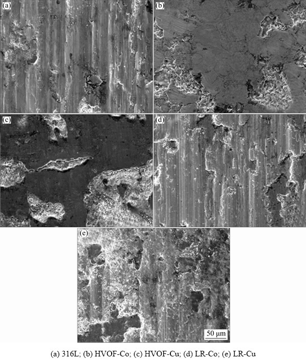
Fig. 5 SEM images of worn surfaces under 15 N
Apart from the delamination areas, smooth areas attract attention. The relatively low coefficient of friction values seen in this sample can be attributed to smooth areas. However, the increase in the friction coefficient was sourced by the increase in the delamination areas. There are plastic deformation and regional spills on the worn surface of the LR-Co sample. In addition, micro scratches created by wear debris are seen. In the LR-Cu sample, although there are wear mechanisms seen in LR-Co, regional spills regions occurred more frequently.
3.3 Isothermal oxidation behavior
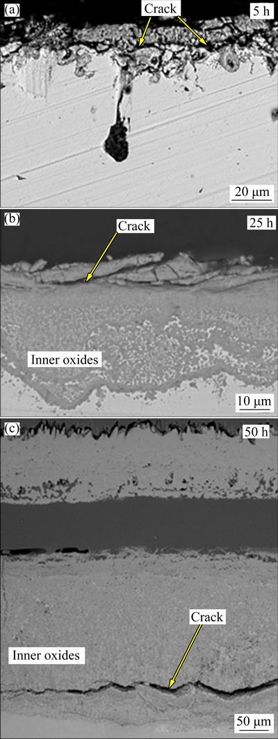
Fig. 6 SEM images of oxidized 316L S.S. after oxidation at 900 ��C
Figure 6 shows the SEM images of 316L S.S. after isothermal oxidation at 900 ��C for 5, 25 and 50 h. Localized oxidation pit formation and crack formation on the oxide surface can be seen after 5 h oxidation. This enables the inner oxide formation in the 316L S.S.. After 25 h oxidation, inner oxide formation can be seen and, oxides including cracks formed. The oxide scale thickness was dramatically increased. The formation of cracks shows that the break-away oxidation period started. After 50 h oxidation, the inner oxide layer includes crack formation and, the top oxide layer delaminated from the inner oxide layer. This delamination may be related to thermal expansion mismatch between inner and upper oxides. The same oxidation tendency was seen in another study for 316L S.S. after high temperature oxidation tests [48]. In 316L S.S., Cr2O3, Fe2O3 and (Fe, Ni)Cr2O4 spinel phase formations can be seen after high temperature oxidation tests. The formed oxides except for Cr2O3 are fast-growing, brittle and porous structure oxides. Therefore, the formation of these oxides can accelerate the delamination or spallation of formed oxide layers.
After isothermal oxidation tests up to 50 h as well as XRD analysis for 50 h oxidation test, SEM images belonging to HVOF Al0.2CrFeNiCu and Al0.2CrFeNiCo are shown in Fig. 7. Both coating layers are delaminated after 50 h oxidation due to high-stress formation and thermal expansion mismatch. Coating layers in both coating systems completely were oxidized in all oxidation stages. Depending on the increasing time, upper regions of coatings include oxides at higher rates. Spallation was observed in Al0.2CrFeNiCu coating while it was not observed in HVOF Al0.2CrFeNiCo at the end of 50 h oxidation. Both coatings produced by non-alloyed powders did not enable a protective oxide layer on the surface. Free elements easily were oxidized and all coatings acted as a ceramic layer. This result causes a thermal expansion mismatch between substrate and coating. In addition, different oxide formations in the coating layer also mismatch and cause an increase in the stress generation. Although the coatings with free elements rapidly oxidized, they prevented the substrate against oxidation. Non-alloyed HVOF Fe/Al coatings show similar oxidation resistance [48]. The obtained XRD results show that formed oxide layer is composed of Cr2O3, spinel oxides and Fe2O3 at the end of the 50 h oxidation test. Especially, three different oxide formations and their mismatch cause a very high-stress generation between HVOF coating layers and 316 L substrate.
Figures 8 and 9 show SEM images and mapping analysis of oxidized laser melted alloys at 900 ��C for 5, 25, 50 and 125 h. Both coatings have a thickened oxide layer depending on time. In the first stage, a slow-growing and compact oxide layer formed in both coating. In the matrix, local fine alumina distribution is seen for both re-melted coatings. Some aluminum was already oxidized during coating. Furthermore, the evaporation of free Al during the re-melting process also caused a low Al concentration in the matrix. Thus, it is thought that alumina formation was not observed on the oxide layer. After 50 h oxidation tests, a dramatic increase was observed in Al0.2CrFeNiCu. In addition, the formed oxide layer includes some micro crack formation due to thermal stress. According to mapping analysis, the formed oxide layer in Al0.2CrFeNiCu consists of Cr2O3 and spinel oxides. The inner layer is composed of a continuous Cr2O3 layer while the upper layer is composed of mixed oxides. This is probably related to the lack of sufficient Cr concentration. The depleted Cr in the matrix caused diffusion of other elements towards the above Cr2O3 layer. In laser re- melted Al0.2CrFeNiCo coating, slow-growing oxide formation is seen compared to larger re-melted Al0.2CrFeNiCu. Similar to Al0.2CrFeNiCu, the highest increase in the oxide thickness was seen after 50 h oxidation yet a lower thickness increase was seen. In addition, a thicker Cr2O3 layer was obtained at the end of the oxidation test compared to Al0.2CrFeNiCu. The lower growing tendency can be attributed to this finding. Similarly, mixed oxide formation was seen above the Cr2O3 layer in Al0.2CrFeNiCo and, the decrease in Cr concentration was observed significantly.
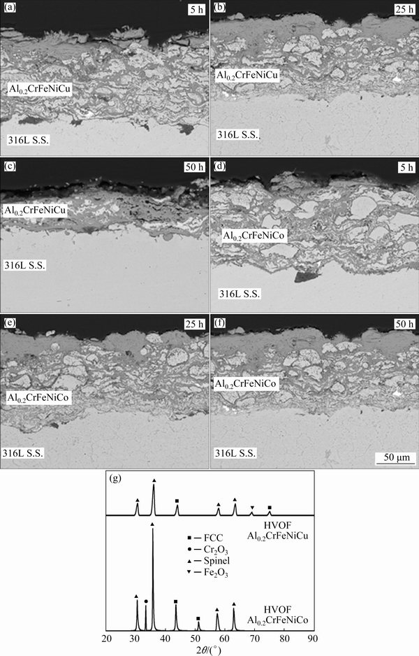
Fig. 7 SEM images of HVOF Al0.2CrFeNiCu (a-c) and Al0.2CrFeNiCo (d-f) after oxidation tests at 900 ��C, and XRD patterns of 50 h oxidized HVOF Al0.2CrFeNiCu and Al0.2CrFeNiCo coatings (g)
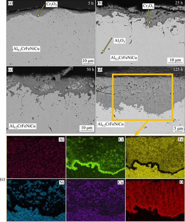
Fig. 8 SEM images (a-d) of re-melted Al0.2CrFeNiCu after oxidation at 900 ��C for 5, 25, 50 and 125 h, and corresponding mappings for 125 h (e)
XRD patterns of 125 h oxidized re-melted coatings and oxide growth graph depending on time are given in Fig. 10. XRD patterns verified the mapping analysis results. Cr2O3 and spinel as formed oxides were detected at the end of the oxidation tests. According to the mapping and XRD analysis below the oxide scale, FCC phases are rich in Fe-Ni-Cu in Al0.2CrFeNiCu while Al0.2CrFeNiCo has FCC phase, rich in Fe-Ni-Co. In re-melted Al0.2CrFeNiCu coating, spinel phase formations are dominant. The formed spinel phases in both samples can be composed of (Co, Ni, Fe)Cr2O4. This can be said by overlappings in elemental mapping. In Al0.2CrFeNiCu, spinel phases with high thickness led to the main phase at the end of the oxidation tests. On the contrary, Cr2O3 is more dominant in Al0.2CrFeNiCo. As a result of these oxide distributions, the oxide growth rate is high in Al0.2CrFeNiCu.
According to the parabolic oxidation rule, the following formula can be used for determining the oxide growth rate:
x2=kpt+C
where x is the oxide thickness (��m), kp is the parabolic rate constant (��m2/h), t is time (h), and C is a constant value. For 5 and 50 h stages, both coatings obey the parabolic oxidation rule and, their rate constant was calculated using the above determined formula and given in Fig. 11. After 50 h oxidation, Al0.2CrFeNiCu exhibits a linear growth. This is related to the mixed oxide formation in this alloy, yet re-melted Al0.2CrFeNiCo follows a slow growth. That��s why its growth obeys the parabolic oxidation rule for 5-125 h. For the comparison, only 5-50 h stage was calculated. According to the obtained rate constant values for 5-50 h stage, there is a significant difference among the HEAs. kp value of Al0.2CrFeNiCu is 1.65, while that of Al0.2CrFeNiCo is 0.61. Difference is nearly 2.5 fold.
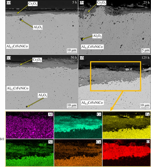
Fig. 9 SEM images (a-d) of re-melted Al0.2CrFeNiCo coatings after oxidation at 900 ��C for 5, 25, 50 and 125 h, and corrpesponding mappings for 125 h (e)
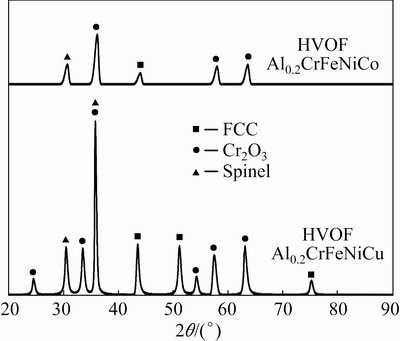
Fig. 10 XRD patterns of oxidized re-melted coatings after 125 h oxidation
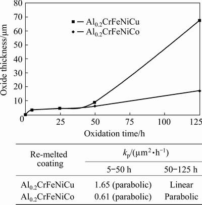
Fig. 11 Oxide growth rate and kp values belonging to re-melted coatings
In the coating elements, the highest affinity to oxygen is Al and Cr, respectively. According to Gibbs free formation energy of formed oxides at 900 ��C, sorting can be made as follows; Al2O3< Cr2O3
4 Conclusions
(1) HVOF sprayed coatings have a structure with oxide due to the use of non-alloyed powder. Especially, some Al was oxidized and/or vaporized during the spraying process.
(2) Compared with HVOF, much more homogeneous and lower porous structure coatings were obtained. A single-phase microstructure was formed in both coatings after laser re-melting.
(3) Average surface hardnesses of 316L, HVOF-Co, HVOF-Cu, LR-Co and LR-Cu samples were HV 186, HV 591, HV 361, HV 259 and HV 270, respectively. It has been observed that the hardness directly affects the wear resistance of the samples.
(4) The best wear resistance was seen in the HVOF-Co coating, while the lowest wear resistance was seen in the 316L substrate. While the increase in load caused an increase in the volume loss of the samples, HVOF coatings were mostly affected.
(5) Low friction coefficient occurred in HVOF coatings due to their oxidized content and relatively smooth worn surfaces. Although the friction coefficients of substrate and laser re-melted samples are similar to each other, they were higher than the HVOF samples. The friction coefficient values coincided with the volume loss and worn surface images.
(6) 316L S.S. exhibits the worst oxidation performance due to the non-continuous oxide formation. After 25 h oxidation, its oxide layer started to spall from the surface and reach very high thickness.
(7) HVOF sprayed coatings show similar oxidation performance. Both of their coating layers were completely oxidized up to 50 h. Afterward, they completely separated from the substrate due to high stress and thermal expansion mismatch.
(8) Laser re-melted coatings endured up to 125 h oxidation tests due to the containing Cr2O3 layer which slowed down the oxygen penetration. Al0.2CrFeNiCo coating has a slower oxide growth rate due to the parabolic growth tendency up to 125 h yet Al0.2CrFeNiCu lost parabolic growth after 50 h and, exhibited linear oxide growing due to the formation of spinel oxide at a high rate above the Cr2O3.
Acknowledgments
This study was financially supported by Scientific Research Funds of Bartin University (No. 2019-FEN-A-012, 2019-FEN-A-013).
References
[1] XU J, CAO C, GU P, PENG L. Microstructures, tensile properties and serrated flow of AlxCrMnFeCoNi high entropy alloys [J]. Transactions of Nonferrous Metals Society of China, 2020, 30(3): 746-755.
[2] PENG J, LI Z, JI X, SUN Y, FU L, SHAN A. Decomposition kinetics of carbon-doped FeCoCrNiMn high-entropy alloy at intermediate temperature [J]. Transactions of Nonferrous Metals Society of China, 2020, 30(7): 1884-1894.
[3] SHABANI A, TOROGHINEJAD M R. Evaluation of microstructure and texture formation during annealing of cold-rolled FeCrCuMnNi multiphase high-entropy alloy [J]. Transactions of Nonferrous Metals Society of China, 2020, 30(2): 449-462.
[4] ERDOGAN A, GOK M S, ZEYTIN S. Analysis of the high-temperature dry sliding behavior of CoCrFeNiTi0.5Alx high-entropy alloys[J]. Friction, 2019, 8(1): 198-207.
[5] JOSEPH J, JARVIS T, WU X. Comparative study of the microstructures and mechanical properties of direct laser fabricated and arc-melted AlxCoCrFeNi high entropy alloys [J]. Materials Science and Engineering A, 2015, 633: 184-193.
[6] YEH J W, CHEN S K, LIN S J. Nanostructured high-entropy alloys with multiple principal elements: Novel alloy design concepts and outcomes [J]. Advanced Engineering Materials, 2004, 6(5): 274: 299-303.
[7] ERDOGAN A, YENER T, ZEYTIN S. Fast production of high entropy alloys (CoCrFeNiAlxTiy) by electric current activated sintering system [J]. Vacuum, 2018, 155: 64-72.
[8] ERDOGAN A, ZEYTIN S. High entropy alloys: Principles and alloy design [J]. Nigde Omer Halisdemir University Journal of Engineering Sciences, 2019, 8(2): 1160-1178.
[9] ERDOGAN A, DOLEKER K M, ZEYTIN S. Effect of Al and Ti on high-temperature oxidation behavior of CoCrFeNi-based high-entropy alloys [J]. JOM, 2019, 71: 3499-3510.
[10] CUI Z, QIN Z, DONG P. Microstructure and corrosion properties of FeCoNiCrMn high entropy alloy coatings prepared by high speed laser cladding and ultrasonic surface mechanical rolling treatment [J]. Materials Letters, 2020, 259: 126769.
[11] LIU H, LIU J, CHEN P. Microstructure and high temperature wear behaviour of in-situ TiC reinforced AlCoCrFeNi-based high-entropy alloy composite coatings fabricated by laser cladding [J]. Optics and Laser Technology, 2019, 118: 140-150.
[12] ERDOGAN A, DOLEKER K M, ZEYTIN S. Effect of laser re-melting on electric current assistive sintered CoCrFeNiAlxTiy high entropy alloys: Formation, micro-hardness and wear behaviors [J]. Surface and Coatings Technology, 2020, 399: 126179.
[13] HSU W, MURAKAMI H, YEH J. On the study of thermal-sprayed Ni0.2Co0.6Fe0.2CrSi0.2AlTi0.2 HEA overlay coating [J]. Surface and Coatings Technology, 2017, 316: 71-74.
[14] CHEN L, BOBZIN K, ZHOU Z. Wear behavior of HVOF-sprayed Al 0.6TiCrFeCoNi high entropy alloy coatings at different temperatures [J]. Surface and Coatings Technology, 2019, 358: 215-222.
[15] PAWLOWSKI L. The science and engineering of thermal spray coatings [M]. London: John Wiley & Sons, 2008.
[16] RODRIGUEZ J, MARTIN A, FERNANDEZ R. An experimental study of the wear performance of NiCrBSi thermal spray coatings [J]. Wear, 2003, 255(7-12): 950-955.
[17] VERDON C, KARIMI A, MARTIN J L. A study of high velocity oxy-fuel thermally sprayed tungsten carbide based coatings. Part 1: Microstructures [J]. Materials Science and Engineering A, 1998, 246(1-2): 11-24.
[18] SIDHU T S, AGRAWAL R D, PRAKASH S. Hot corrosion of some superalloys and role of high-velocity oxy-fuel spray coatings��A review [J]. Surface and Coatings Technology, 2005, 198(1-3): 441-446.
[19] SUN Z, ANNERGREN I, PAN D. Effect of laser surface remelting on the corrosion behavior of commercially pure titanium sheet [J]. Materials Science and Engineering A, 2003, 345(1-2): 293-300.
[20] GUSAROV A V, PAVLOV M, SMUROV I. Residual stresses at laser surface remelting and additive manufacturing [J]. Physics Procedia, 2011, 12A: 248-254.
[21] PETROV P. Electron beam surface remelting and alloying of aluminium alloys [J]. Vacuum, 1997, 48(1): 49-50.
[22] TIANSHUN D, XIUKAI Z, GUOLU L. Microstructure and corrosive wear resistance of plasma sprayed Ni-based coatings after TIG remelting [J]. Materials Research Express, 2018, 5(2): 026411.
[23] WANG C, YU J, ZHANG Y. Phase evolution and solidification cracking sensibility in laser remelting treatment of the plasma-sprayed CrMnFeCoNi high entropy alloy coating [J]. Materials and Design, 2019, 182: 108040.
[24] YANG X, LIU J, CUI X. Effect of remelting on microstructure and magnetic properties of Fe-Co-based alloys produced by laser additive manufacturing [J]. Journal of Physics and Chemistry of Solids, 2019, 130: 210-216.
[25] TEMMLER A, WILLENBORG E, WISSENBACH K. Design surfaces by laser remelting [J]. Physics Procedia, 2011, 12A: 419-430.
[26] EVANS H E. Stress effects in high temperature oxidation of metals [J]. International Materials Reviews, 1995, 40(1): 1-40.
[27] BRADY M P, WRIGHT I G, GLEESON B. Alloy design strategies for promoting protective oxide-scale formation [J]. JOM, 2000, 52(1): 16-21.
[28] FAN Q C, LI B S, ZHANG Y. Influence of Al and Cu elements on the microstructure and properties of (FeCrNiCo) AlxCuy high-entropy alloys [J]. Journal of Alloys and Compounds, 2014, 614: 203-210.
[29] MOHANTY A, SAMPREETH J K, BEMBALGE O. High temperature oxidation study of direct laser deposited AlXCoCrFeNi (X=0.3,0.7) high entropy alloys [J]. Surface and Coatings Technology, 2019, 380: 125028.
[30] LI Q, CHEN W, ZHONG J. On sluggish diffusion in FCC Al�CCo�CCr�CFe�CNi high-entropy alloys: An experimental and numerical study [J]. Metals, 2018, 8(1): 16.
[31] WANG J, GUO T, LI J. Microstructure and mechanical properties of non-equilibrium solidified CoCrFeNi high entropy alloy [J]. Materials Chemistry and Physics, 2018, 210: 192�C196.
[32] LIVERANI E, TOSCHI S, CESCHINI L. Effect of selective laser melting (SLM) process parameters on microstructure and mechanical properties of 316L austenitic stainless steel [J]. Journal of Materials Processing Technology, 2017, 249: 255-263.
[33] YAKOUT M, ELBESTAWI M A, VELDHUIS S C. A study of thermal expansion coefficients and microstructure during selective laser melting of Invar 36 and stainless steel 316L [J]. Additive Manufacturing, 2018, 24: 405-418.
[34] AMATO K N, GAYTAN S M, MURR L E. Microstructures and mechanical behavior of Inconel 718 fabricated by selective laser melting [J]. Acta Materialia, 2012, 60(5): 2229-2239.
[35] SAEIDI K, GAO X, ZHONG Y. Hardened austenite steel with columnar sub-grain structure formed by laser melting [J]. Materials Science and Engineering A, 2015, 625: 221-229.
[36] FU Z, CHEN W, WEN H. Effects of Co and sintering method on microstructure and mechanical behavior of a high-entropy Al0.6NiFeCrCo alloy prepared by powder metallurgy [J]. Journal of Alloys and Compounds, 2015, 646: 175-182.
[37] CHEN Z, CHEN W, WU B. Effects of Co and Ti on microstructure and mechanical behavior of Al0.75FeNiCrCo high entropy alloy prepared by mechanical alloying and spark plasma sintering [J]. Materials Science and Engineering A, 2015, 648: 217-224.
[38] GU Z, XI S, SUN C. Microstructure and properties of laser cladding and CoCr2.5FeNi2Tix high-entropy alloy composite coatings [J]. Journal of Alloys and Compounds, 2020, 819: 152986.
[39] ZHANG G J, TIAN Q W, YIN K X. Intermetallics Effect of Fe on microstructure and properties of AlCoCrFexNi (x=1.5, 2.5) high entropy alloy coatings prepared by laser cladding [J]. Intermetallics, 2020, 119: 106722.
[40] MATERIALS H, PENG Y B, ZHANG W. International Journal of Refractory Metals Microstructures and mechanical properties of FeCoCrNi high entropy alloy/WC reinforcing particles composite coatings prepared by laser cladding and plasma cladding [J]. 2019, 84: 1-9.
[41] TAKEUCHI A, INOUE A. Classification of bulk metallic glasses by atomic size difference, heat of mixing and period of constituent elements and its application to characterization of the main alloying element[J]. 2005, 46(12): 2817-2829.
[42] MU Y K, JIA Y D, XU L. Nano oxides reinforced high- entropy alloy coatings synthesized by atmospheric plasma spraying [J]. Materials Research Leters, 2019, 7(8): 312-319.
[43] ERDOGAN A, GOK M S, KOC V. Friction and wear behavior of epoxy composite filled with industrial wastes [J]. Journal of Cleaner Production, 2019, 237: 117588.
[44] YENER T, ERDOGAN A, GOK M S. Nb and B effect on mechanical properties of Ti-Al based intermetallic materials [J]. Vacuum, 2019, 169: 108867.
[45] MU Y, ZHANG L, XU L. AlCoCrFeNi high-entropy alloy coatings [J]. Entropy, 2020, 22: 740.
[46] ZHANG Q Y, ZHOU Y, LIU J Q. Wear behavior and mechanism of Fe-Al intermetallic coating prepared by hot-dip aluminizing and diffusion [J]. Metallurgical and Materials Transactions A: Physical Metallurgy and Materials Science, 2016, 47(5): 2232-2242.
[47] da CONCEICAO L, D��OLIVEIRA A S C M. The effect of oxidation on the tribolayer and sliding wear of a Co-based coating [J]. Surface and Coatings Technology, 2016, 288: 69-78.
[48] DOLEKER K M. The examination of microstructure and thermal oxidation behavior of laser-remelted high-velocity oxygen liquid fuel Fe/Al coating [J]. Journal of Materials Engineering and Performance, 2020, 29: 3220-3232.
[49] HASEGAWA M. Ellingham diagram [M]. Stockholm, Sweden: Treatise on Process Metallurgy Elsevier Ltd., 2013: 507-516.
[50] RABIEI A, EVANS A G. Failure mechanisms associated with the thermally grown oxide in plasma-sprayed thermal barrier coatings [J]. Acta Mater, 2000, 48(15): 3963-3976.
[51] SAUNDERS S R J, MONTEIRO M, RIZZO F. The oxidation behaviour of metals and alloys at high temperatures in atmospheres containing water vapour: A review [J]. Progress in Materials Science, 2008, 53(5): 775-837.
[52] STYGAR M, BERENT K, CIESLAK G. Influence of Cu content on high temperature oxidation behavior of AlCoCrCuxFeNi high entropy alloys (x=0; 0.5; 1) [J]. Intermetallics, 2017, 84: 52-61.
[53] LIU Y Y, CHEN Z, CHEN Y Z. Effect of Al content on high temperature oxidation resistance of AlxCoCrCuFeNi high entropy alloys (x=0, 0.5, 1, 1.5, 2) [J]. Vacuum, 2019, 169: 108837.
[54] LIU Y X, CHENG C Q, SHANG J L. Oxidation behavior of high-entropy alloys AlxCoCrFeNi (x=0.15,0.4) in super- critical water and comparison with HR3C steel [J]. Transactions of Nonferrous Metals Society of China, 2015, 25(4): 1341-1351.
Azmi ERDOGAN1, Kadir Mert DOLEKER2
1. Department of Metallurgy and Materials Engineering, Faculty of Engineering Architecture and Design, Bartin University, Bartin, Turkey;
2. Department of Metallurgy and Materials Engineering, Faculty of Engineering, Ondokuz Mayis University, Samsun, Turkey
ժ Ҫ���ó����ٻ�����Ϳ(HVOF)����316L����ֻ����ϳ���Al0.2CrFeNiCo��Al0.2CrFeNiCu���ָ��غϽ�Ϳ�㣬Ȼ���Ϳ����м�������(LR)�Ը���������֯���о�LR���ն�Ϳ��ɻ���ĥ���������Ϊ��Ӱ�졣�������������ĩ�뵥��Ԫ�ػ�ϵ���HVOFͿ�����γ��������LR����������������ס�LR�����ֺϽ��о���FCC��Ϊ��������Al0.2CrFeNiCo�Ͻ��й۲쵽BCC��sigma��Cr2O3�ࡣHVOF��Al0.2CrFeNiCo�� Al0.2CrFeNiCu Ϳ���Ӳ�ȷֱ�ΪHV 591��HV 361��LR����Ӳ�ȷֱ��С��HV 259��HV 270����������Ʒ��ȣ���ȻHVOFͿ�����غ����ӵ�Ӱ���������ֳ���ߵ���ĥ�ԣ��һ������ĥ��������ʵ���HVOFͿ�㱻��ȫ����������50 h��Ϳ�������ṹ�ӻ��������䡣LRͿ����нϺõĿ��������ܡ�����ʵ���Al0.2CrFeNiCoͿ����Ҫ��Cr2O3��������ɣ�Cr2O3������������ʵ����ڵ������ٶȽ�������Al0.2CrFeNiCuͿ������Ҫ�ɼ⾧ʯ����ɡ�
�ؼ��ʣ����غϽ𣻼������ۣ������ٻ�����Ϳ(HVOF)��ĥ������
(Edited by Xiang-qun LI)
Corresponding author: Kadir Mert DOLEKER, E-mail: mert.doleker@omu.edu.tr
DOI: 10.1016/S1003-6326(21)65664-9
1003-6326/ 2021 The Nonferrous Metals Society of China. Published by Elsevier Ltd & Science Press

