Trans. Nonferrous Met. Soc. China 28(2018) 1233-1240
Turning traction force of tracked mining vehicle based on rheological property of deep-sea sediment
Feng XU1, Qiu-hua RAO1, Wen-bo MA2
1. School of Civil Engineering, Central South University, Changsha 410075, China;
2. College of Civil Engineering and Mechanics, Xiangtan University, Xiangtan 411100, China
Received 21 December 2016; accepted 18 July 2017
Abstract: Based on main physical and mechanical properties of deep-sea sediment from C-C poly-metallic nodule mining area in the Pacific Ocean, the best sediment simulant was successfully prepared by mixing bentonite with a certain content of water. Compression-shear coupling rheological constitutive model of the sediment simulant was established by endochronic theory and the coupling rheological parameters were obtained by compressive and compression-shear creep tests. A new calculation formula of turning traction force of the tracked mining vehicle was first derived based on the coupling rheological model and consideration of pushing resistance and sinkage of the tracked mining vehicle. Effects of the turning velocity, crawler spacing and contacting length of crawler with deep-sea sediment on the turning traction force were analyzed. Research results can provide theoretical foundation for operation safety and optimal design of the tracked mining vehicle.
Key words: turning traction force; compression-shear coupling rheology; deep-sea sediment; tracked mining vehicle
1 Introduction
With increasing consumption and depletion of land resource, many countries have focused more and more attention on deep-sea resource exploitation, since there are a lot of poly-metallic nodules and sulfides on deep-sea bed [1-3]. Currently, three kinds of deep-sea mining systems have been developed, i.e., continuous chain-bucket system, shuttle down-the-hole lift system, and compressed air hydraulic lift system. The last one is often used in China [4,5], which consists of five parts: mining ship, flexible hose, buffer, rigid pipe and tracked mining vehicle. Obviously, the tracked mining vehicle is a key subsystem and its moving performance (straight-line or turning) plays an important role in mining safety and efficiency. For example, poor turning traction force of the tracked mining vehicle would result in turnover, deficient mining and repetitive mining [6,7]. Since the deep-sea sediment has higher water content, greater void, and more obvious rheological property than land soil [8-10], it is very necessary to study effect of rheological property of the deep-sea sediment on turning traction force of the tracked mining vehicle.
Currently, turning traction force of the tracked vehicle was studied mainly by experimental and numerical simulation method [11-15], such as relationships of the turning traction force with turning radius, turning velocity and thrust ratio. Few literatures were focused on turning theory with the following assumptions: 1) the ground is hard and 2) the crawler sinkage and pushing effect of the crawler in the lateral direction are neglected [11,15]. Obviously, this turning theory is suitable for most hard land ground but not for soft deep-sea bed, because large crawler sinkage and pushing effect of the crawler caused by the deep-sea sediment can not be neglected.
In this study, the best sediment simulant was prepared based on main physical and mechanical properties of the deep-sea sediment and used to conduct compressive and compression-shear creep tests. Compression-shear coupling rheological constitutive model of the sediment simulant was established by endochronic theory and applied to deducing a new calculation formula of turning traction force for the tracked mining vehicle, with consideration of its pushing resistance and sinkage. Effects of the turning velocity, crawler spacing and contacting length of crawler with deep-sea sediment on the turning traction force were analyzed in order to provide theoretical foundation for operation safety and optimal design of the tracked mining vehicle.
2 Preparation of deep-sea sediment simulant
2.1 Macroscopic and microscopic properties of deep- sea sediment
2.1.1 Physical and mechanical properties
A micro-plus laser diffraction particle size analyzer was used to measure granule diameter of deep-sea sediment [8]. Figures 1 and 2 show the granule diameter (d)-accumulated mass (m) curve and the average granule diameter (d′)-frequency (f ) curve, respectively. Table 1 lists its main characteristics of the granule diameter. It is seen that the deep-sea sediment is mainly composed of grit (0.06%), silt (67.22%), clay (32.72%) and idiosome (13.44%), in which the number in bracket are volume fractions [8].
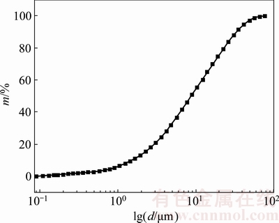
Fig. 1 d-m curve of deep-sea sediment

Fig. 2 d′-f curve of deep-sea sediment
A LG-100D digital liquid-plastic limit determinator and a Autosorb-SI automated specific surface area analyzer were adopted to measure liquid limit (wL), liquid limit index (IL), and specific surface area (Sg) of the deep-sea sediment, respectively [8]. It can be obtained that its liquid limit index IL is 2.15 (IL>1) and specific surface area Sg is 53.8 m2/g, indicating that the deep-sea sediment is flowable and has high content of montmorillonite with large specific surface area (because of high volume fraction of silt and clay).
Table 2 lists the main physical and mechanical parameters of different soils, where void ratio (e) is obtained by consolidation test, and shear strength parameters (c and φ) are obtained by direct shear test. It is seen that the deep-sea sediment has larger void ratio, larger water content, higher liquid limit and smaller shear strength than other soils.
2.1.2 Mineral component and microstructure
A D/max 2550 X-ray diffractometer was used to analyze component of the deep-sea sediment [8]. It can be found from Fig. 3 that the deep-sea sediment consists of primary minerals (quartz, feldspar and glimmer) and secondary minerals (montmorillonit, chlorite and taxoite). The secondary minerals play a decisive role in the physical and mechanical properties of the deep-sea sediment.
Table 1 Granule diameters of deep-sea sediment

Table 2 Main physical and mechanical parameters of different soils

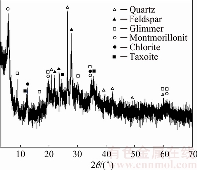
Fig. 3 XRD pattern of deep-sea sediment
The microstructure of the deep-sea sediment was analyzed by a JSM-6360LV scanning electron microscope (Fig. 4). It is seen that the deep-sea sediment has loose honeycomb microstructures flocculated by flaky clay minerals of very small thickness and thus large water content, high void ratio, low strength and high compressibility.
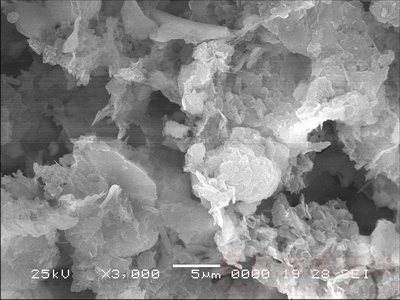
Fig. 4 SEM image of deep-sea sediment
2.2 Preparation of sediment simulant
Since bentonite has similar mineral components to the deep-sea sediment (with large content of montmorillonit), it can be used to prepare sediment simulant by mixing with a certain content of water in order to have the same shear strength as the deep-sea sediment [8]. Table 3 lists the main physical and mechanical parameters of the best sediment simulant as well as the deep-sea sediment for comparison.
3 Rheological constitutive model of sediment simulant
3.1 Compressive rheological constitutive model of sediment simulant
3.1.1 Compressive creep test
Figure 5 shows a self-designed compressive creep test, in which the sediment simulant specimen of 450 mm × 450 mm × 500 mm in size was put in an iron container (with the same size) and loaded by different steel weights on bearing plates for different constant compressive stresses (σ=5, 10, 15, 20, 25, 30 kPa). A displacement sensor on the bearing plate was used to record vertical displacement (z) every second until z tended to be stable.
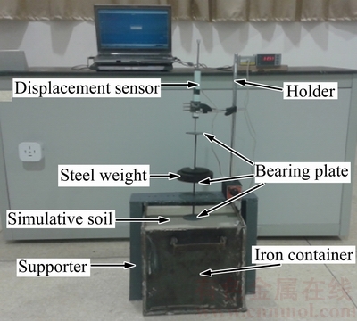
Fig. 5 Compressive creep test
3.1.2 Compressive rheological constitutive equation
Figure 6 illustrates the compressive creep curves of the sediment simulant under different σ. Kelvin-Hooke rheological model (Eq. (1)) was adopted to fit these z-t curves.
 (1)
(1)
where and
and are compressive elastic parameters proportional to the compressive elastic modulus E1 and E2, respectively, and
  is viscous parameter proportional to the viscosity η. Obviously, σ-z equation has the same form as σ-e equation except for , and instead of E1, E2 and η.
Table 3 Main physical and mechanical parameters of deep-sea sediment and its stimulant
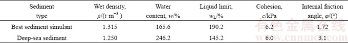
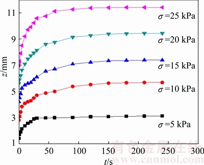
Fig. 6 Compressive creep curves under different σ
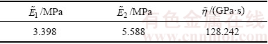
For each z-t curve, its rheological parameters (, and ) for specific constant σ can be obtained by fitting Eq. (1) with the test data. In order to determine unified rheological parameters (, , and ) for different constant σ, all of test data were plotted in a spatial coordinate of z-t-σ and fitted by Eq. (1) to be a curved surface with high precision (coefficient of determination R2=0.985), as shown in Fig. 7 and Table 4.
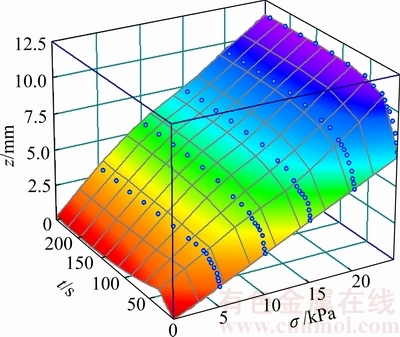
Fig. 7 Fitted curved surface in z-t-σ space with test data
Table 4 Compressive rheological parameters
3.2 Compression-shear coupling rheological constitutive model of sediment simulant
3.2.1 Compression-shear creep test
Figure 8 shows a self-designed compression-shear creep instrument, in which the sediment simulant specimen of d61.8 mm × 40 mm in size (Fig. 9) was placed in a shear box (part a) under different constant compressive stresses (σ=5, 10, 15, 20, 25, 30 kPa) by different weights (part e) and constant shear stresses (τ=1, 2, 3, 4, 5, 6 kPa) by different weights (part e′). Compressive and shear displacements were measured by NS-WY02 displacement censors (parts b and b′) with high precision, amplified by signal amplifiers (parts c and c′), and displayed by indicators (parts d and d′), respectively. Since the indicators (parts d and d′) can display but not save instant data, a computer (part f) with NS-YB data acquisition software was needed to connect the indicators (parts d and d′) for storage of test data.
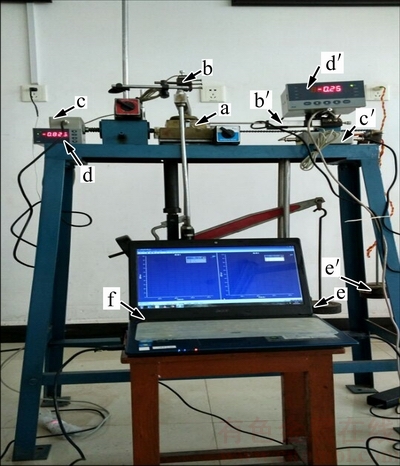
Fig. 8 Compression-shear creep test instrument

Fig. 9 Sediment simulant specimen in shear box
3.2.2 Compression-shear coupling rheological constitutive equation
Figure 10 shows the compressive displacement curves (z-t) and shear displacement curves (s-t) of the sediment simulant for different σ under the same τ (τ=3 kPa). It is seen that z-t curves are different for different σ but s-t curves are also different for different σ. This means the shear displacement s is influenced not only by τ but also by σ. Figure 11 shows s-t curves and z-t curves for different τ under the same σ (σ=15 kPa). Similarly, s-t curves are different for different τ but z-t curves are also different for different τ , indicating that z is influenced not only by σ but also by τ. It can be concluded that there exists compression-shear coupling rheological effect of deep-sea sediment under the interaction of σ and τ.

Fig. 10 Compression-shear creep curves of sediment simulant for different σ under same τ (τ=3 kPa)
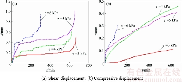
Fig. 11 Compression-shear creep curves of sediment simulant for different τ under same σ (σ=15 kPa)
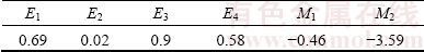
Since element rheological model is very complicated to describe two-dimensional rheological characteristics, endochronic theory is adopted to establish the compression-shear coupling logical constitutive model of the sediment simulant (see Eq. (2)) [16]. The rheological parameters can be determined by compressive creep test, direct shear creep test and compression-shear creep test (see Table 5) [16].
 (2)
(2)
Table 5 Compression-shear coupling rheological parameters of sediment simulant [16]
4 Turning traction force of tracked mining vehicle
4.1 Calculation formulae of turning traction force
Set a fixed coordinate system (XOY) on the deep seabed and a moving coordinate system (xoy) on the tracked vehicle body. When the tracked mining vehicle rotates around point O with radius r′ at linear velocity v and angular velocity ω (Fig. 12), the inner crawler (closer to the point O) and the outer crawler (far from the point O) turn around instantaneous velocity centers Oi and Oo at velocity vi and vo, respectively. Assuming that the tracked mining vehicle turns at different velocities of the inner and outer crawlers (i.e., vio) and the distance between centroid O′ and shape center O″ is S0, there exist geometric relationships as follows:
 (3)
(3)
 (4)
(4)
 (5)
(5)
where B is the crawler spacing.

Fig. 12 Force and motion analyses of tracked vehicle at turning
When the tracked mining vehicle turns on the deep seabed, it is subjected to centrifugal force component Fcx from O′ and pushing resistance forces FT1 and FT2 at both lateral sides of each crawler in x direction of coordinate system xoy. According to Ref. [17], there is
FT=8.817z+12.82 (6)
Assuming that the ground pressure of each crawler is uniformly distributed, when a point a(x, y, 0) on the crawler moves from location A to B (see Fig. 12(b)), its total sinkage (Z) is concerned with time t and thus can be determined by integral of Eq. (1) as follows:
 (7)
(7)
where t=L/v (L is contacting length of crawler with the deep-sea sediment) and p=W/(2bL) (W is weight and b is width of the tracked mining vehicle)
In the y-direction of the coordinate system xoy, the tracked mining vehicle is subjected to centrifugal force component Fcy from centroid O′, motion resistances Ri and Ro, and turning traction forces Fi and Fo for each crawler. Since the motion resistance of every point under inner and outer crawlers satisfies Eq. (2), total motion resistance of each crawler in the y direction can be obtained as follows:

 (8)
(8)
where s is the displacement at the point O′ in the y direction (s=ωt).
According to definition of the centrifugal forces at point O′, there are
 (9)
(9)
 (10)
(10)
where  and
and  .
.
Based on dynamic equilibrium equations of the tracked mining vehicle for forces in the x and y directions and moment of force with respect to point O′:
 (11)
(11)
The traction forces of inner and outer crawlers in the y-direction can be determined by Eq. (11) and Eqs. (3)-(8) respectively as follows:

 (12)
(12)

 (13)
(13)
According to Eqs. (12) and (13), Matlab software with self-designed program is needed to calculate Fi and Fo varying with turning velocity (v), crawler spacing (B) and contacting length with deep-sea sediment (L).
4.2 Influencing factors of turning traction force
4.2.1 Turning velocity (v)
Figure 13 shows the turning traction forces (Fi and Fo) varying with the turning radius (r) at different turning velocities (v). It is seen that all of Fi-r curves are almost symmetric with respect to the r axis with their Fo-r curves. When the tracked mining vehicle (W=225 kN) turns at different r, the s traction force (Fi or Fo) is gradually increased when 01 m. The larger the turning velocity is, the higher the peak value of the traction force is. This is because a higher turning velocity can result in a shorter contacting time of crawler with the deep-sea sediment and a smaller motion resistance Ri and Ro (Eq. (8)), and thus a larger traction force. It is an effective way to increase the turning velocity for promoting traction force of the tracked mining vehicle.

Fig. 13 Fi-r and Fo-r curves at different turning velocities (B=2.4 m, L=3.3 m, b=1.0 m)
4.2.2 Crawler spacing (B)
Figure 14 shows the turning traction force (Fi and Fo) varying with turning radius r at different crawler spacings (B). It is seen that the peak values of Fi and Fo are slightly changed with B and quite different from Fig. 13. The larger the B is, the larger the r at peak value of Fi or Fo is. This is because the tracked mining vehicle with a larger B needs a larger force moment for making a turn. When the peak values of Fi and Fo are almost unchanged, a larger r is required to produce a larger force moment. Therefore, when the tracked mining vehicle has to turn at a larger radius r, it is better to choose a larger crawler spacing (B).

Fig. 14 Fi-r and Fo-r curves at different crawler spacings (L=3.3 m, b=1.0 m, v=1.0 m/s)
4.2.3 Contacting length with deep-sea sediment (L)
Figure 15 shows turning traction force (Fi and Fo) varying with different turning radii r at different contacting lengths (L). It is found that L has great effects on peak values of Fi and Fo but not on r at peak values of Fi or Fo. When L is increased, the pushing resistance (FT) and motion resistance (Ro, Ri) are increased and thus Fi and Fo are also increased.
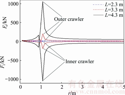
Fig. 15 Fi-r and Fo-r curves at different contacting lengths (B=2.4 m, b=1.0 m, v=1.0 m/s)
5 Conclusions
1) Based on main mineral component and physical and mechanical properties of the deep-sea sediment, the best sediment simulant can be successfully prepared by mixing bentonite with a certain content of water.
2) Compression-shear coupling rheological effect is first proven in compression-shear rheological test. Compression-shear coupling rheological constitutive model can be established by endochronic theory, which has an advantage over element rheological model in describing two-dimensional rheological characteristics.
3) A calculation formula of turning traction force of the tracked mining vehicle is firstly derived based on compression-shear coupling rheological property of the deep-sea sediment and consideration of pushing resistance and sinkage of the tracked mining vehicle, which is more reasonable for deep-sea soft sediment than the current turning theory for hard land ground (without consideration of pushing resistance and sinkage).
4) The turning traction force of inner crawler is almost the same as that of outer crawler. Their peak values are both increased when the turning velocity and contacting length are increased. The crawler spacing has little effect on their peak values, but direct proportional effect on turning radium at their peak values. It is better to design a larger crawler spacing for the tracked mining vehicle when it has to turn at a larger radius.
Acknowledgements
The authors express their thanks to the State Key Laboratory of Exploitation and Utilization of Deep Sea Mineral Resources (Joint Lab of Central South University and Changsha Research Institute of Mining and Metallurgy) for technical support.
References
[1] PARK Y C, YOON C H, LEE D K, KWON S K. Experimental studies on hydraulic lifting of solid-liquid two-phase flow [J]. Ocean & Polar Research, 2004, 26(4): 647-653.
[2] LIU Shao-jun, LIU Chang, DAI Yu. Status and progress on researches and developments of deep ocean mining equipments [J]. Journal of Mechanical Engineering, 2014, 50(2): 8-18. (in Chinese)
[3] WANG Cheng-yan, QIU Ding-fan, YIN Fei, WANG Han-yuan, CHEN Yong-qiang. Slurry electrolysis of ocean polymetallic nodule [J]. Transactions of Nonferrous Metals Society of China, 2010, 20(S1): s60-s64.
[4] XU Hai-liang, HE Qing-hua. Research on the sea mining system [J]. China Mining Magazine, 2004, 13(7): 43-46.
[5] LI Yan, LIU Shao-jun. Virtual prototype and dynamic behavior analysis of deep-ocean mining system [J]. Journal of System Simulation, 2006, 18(8): 2192-2194.
[6] DAI Yu. The modeling research and simulation analysis on the single-rigid-body of tracked miner moving on the seafloor [D]. Changsha: Central South University, 2010. (in Chinese)
[7] HAN Qing-jue, LIU Shao-jun. Slip control of deep sea tracked miner based on dynamic analysis [J]. Journal of Central South University (Science and Technology), 2013, 44(8): 3166-3172. (in Chinese)
[8] MA Wen-bo, RAO Qiu-hua, WU Hong-yun, GUO Shuai-cheng, LI Peng. Macroscopic properties and microstructure analyses of soft seabed soil in deep-sea [J]. Rock and Soil Mechanics, 2014, 35(6): 1641-1646. (in Chinese)
[9] MA Wen-bo, RAO Qiu-hua, LI Peng. Shear creep parameters of simulative soil for deep-sea sediment [J]. Journal of Central South University, 2014, 12(21): 4682-4689.
[10] MA Wen-bo, RAO Qiu-hua, XU Feng, FENG Kang. Impact compressive creep characteristics of simulative soil for deep-sea sediment [J]. Marine Georesources & Geotechnology, 2015, 34(4): 356-364.
[11] WANG Hong-yan, LI Hao-zhan, WANG Tao, RUI Qiang. The analysis and test for the steering process of tracked vehicles on the hard road [J]. 2nd International Conference on Advances in Computer Science and Engineering (CSE 2013). Pairs: Atlantis Press, 2013: 254-258.
[12] SHEN Xian-fa, ZHOU Hong-ping, XU Lin-yun. RecurDyn-based simulation of unilateral brake steering for tracked spraying vehicles on soft ground [J]. Journal of Machine Design, 2015(5): 57-61.
[13] KITANO M, KUMA M. An analysis of horizontal plane motion of tracked vehicles [J]. Journal of Terramechanics, 1977, 14(4): 211-225.
[14] PLESSIS H L, YU T. Modeling the traction of a prototype track based on soil-rubber friction and adhesion [J]. Journal of Terramechanics, 2006, 43(4): 487-504.
[15] WONG J Y, CHIANG C F. A general theory for skid steering of tracked vehicles on firm ground [J]. Proceedings of the Institution of Mechanical Engineers, Part D: Journal of Automobile Engineering. 2001, 215(3): 343-355.
[16] XU Feng, RAO Qiu-hua, ZHANG Jie, MA Wen-bo. Compression-shear coupling rheological constitutive model of the deep-sea sediment [J]. Marine Georesources & Geotechnology, 2018, 36(3): 288-296.
[17] MA Wen-bo, RAO Qiu-hua, FENG Kang, XU Feng. Experimental research on grouser traction of deep-sea mining machine [J]. Applied Mathematics and Mechanics, 2015, 36(9): 1243-1252.
深海底质流变特性对履带式集矿机转弯牵引力的影响
许 锋1,饶秋华1,马雯波2
1. 中南大学 土木工程学院,长沙 410075;2. 湘潭大学 土木工程与力学学院,湘潭 411100
摘 要:基于采自太平洋C-C矿区深海原状底质土的主要物理和力学特性,通过将膨润土与特定比例的水进行混合成功配制出最佳深海模拟底质土。基于内时理论建立深海模拟底质土压-剪耦合流变本构方程,并采用压缩蠕变试验和压-剪蠕变试验得到相应的压-剪耦合流变参数。通过首次考虑深海模拟底质土耦合流变模型和履带式集矿机沉陷与推土阻力,推导出一种新的集矿机转弯牵引力计算公式,并详细分析履带式集矿机转弯速度、履带间距和履带接地长度对转弯牵引力的影响规律。研究结果为履带式集矿机的深海作业安全和优化设计提供了理论基础。
关键词:转弯牵引力;压-剪耦合流变;深海底质;履带式集矿机
(Edited by Xiang-qun LI)
Foundation item: Projects (51274251, 11502226) supported by the National Natural Science Foundation of China
Corresponding author: Qiu-hua RAO; Tel: +86-731-88836423; E-mail: raoqh@csu.edu.cn
DOI: 10.1016/S1003-6326(18)64761-2

