����Ħ�����ӹ��������Ͻ��벻ͬ���ν���ͷ�����������
��Դ�ڿ����й���ɫ����ѧ��(Ӣ�İ�)2019���3��
�������ߣ����� ����� ������ �γ�Ⱥ
����ҳ�룺495 - 506
�ؼ��ʣ�����Ħ����������ͷ���Σ���ѭ��������ͷ����Ť�أ���������
Key words��friction stir welding; tool profile; thermal cycle; tool spindle torque; tensile properties
ժ Ҫ���о�����Ħ����(FSW)�����н���ͷ��״��AA6061-T6���������ͷ����������õ�Ӱ�졣FSW�ӹ������У����ö��Ƶ�ʵ��װ����ɶ��������¶Ⱥͽ���ͷ����Ť�صIJ�����ͬʱ�Խ�����(SZ)����֯���������ܽ��б�����������������ͽ�������״�ֱ�Ӱ��������IJ��ȡ�����ν���ͷŤ�غͽ������������״������ϵİ��ۺͽ������ϵ�����ʹ�������еľ�������ϸ�����������ϵ���ƽ�����²����ȵľ����ߴ硣����Բ���ν�����Ľ���ͷ���Եõ�0.2%����ǿ��Ϊ173 MPa�ĺ��죬��������ƽ�������ν�����Ľ���ͷ���Եõ��쳤��32.0%�ĺ��졣
Abstract: The influence of the tool profiles on the thermo-mechanical interaction between AA6061-T6 workpiece and tool during friction stir welding was investigated. A customized experimental setup was employed to measure the feature points temperature and tool spindle torque in the process of FSW. Microstructure and tensile properties of stir zone (SZ) were characterized. Results indicate that the shoulder and pin geometries were responsible for the heat generation, tool torque variation at the plunging stage as well as the cross section contour of SZ, respectively. Finer grains in SZ resulted from flutes on shoulder and grooves on pin. Flat faces on the pin resulted in inhomogeneous grain size. Weld with higher 0.2% yield strength of 173 MPa was obtained by using the cylindrical pin tool while higher elongation weld of 32.0% was produced with triflat threaded pin tool.
Trans. Nonferrous Met. Soc. China 29(2019) 495-506
Min Yang1, Rui-jun Bao1, Xiu-zhong Liu1, Chao-qun Song2
1. Key Laboratory for Liquid-Solid Structural Evolution and Processing of Materials,
Ministry of Education, Shandong University, Ji��nan 250061, China;
2. State Key Laboratory of Advanced Welding and Joining, Harbin Institute of Technology, Harbin 150001, China
Received 17 March 2018; accepted 10 October 2018
Abstract: The influence of the tool profiles on the thermo-mechanical interaction between AA6061-T6 workpiece and tool during friction stir welding was investigated. A customized experimental setup was employed to measure the feature points temperature and tool spindle torque in the process of FSW. Microstructure and tensile properties of stir zone (SZ) were characterized. Results indicate that the shoulder and pin geometries were responsible for the heat generation, tool torque variation at the plunging stage as well as the cross section contour of SZ, respectively. Finer grains in SZ resulted from flutes on shoulder and grooves on pin. Flat faces on the pin resulted in inhomogeneous grain size. Weld with higher 0.2% yield strength of 173 MPa was obtained by using the cylindrical pin tool while higher elongation weld of 32.0% was produced with triflat threaded pin tool.
Key words: friction stir welding; tool profile; thermal cycle; tool spindle torque; tensile properties
1 Introduction
Friction stir welding (FSW) has been increasingly adopted in the welding of aluminum alloy since it was invented [1]. As for a thermo-mechanical process, heat and forces are generated during FSW due to interaction between the tool and workpiece. The material flow, the microstructure and properties of friction stir welded joints are affected accordingly [2].
Simulations [3,4] on friction stir welding of AA7050-T7451 aluminum alloy indicated that the shoulder-plate contact surface is the main factor for the heat generation in FSW and higher temperature of plasticized material results in lower flow stresses and easier material flow. Given the importance of tool spindle torque on welds performance, HATTINGH et al [5] investigated the influences of FSW tool geometry on welding forces. According to the authors, variation of tool spindle torque hinges on specific geometric details of the tool. Previous researches show that the material flow in the process of FSW is predominantly controlled by the tool pin and shoulder profiles [6,7]. KADIAN and BISWAS [8] studied the influence of tool pin profile on the material flow characteristics of AA6061, confirming that the mixing of the material was better near the probe base region for circular pin profile while the flat surface profiles did not provide lateral and upside material movement. BUFFA et al [9] found that a cylindrical pin showed wider nugget width due to large area at the sheet-sheet interface and conical pin shows a vertical helicoidal material flow in FSW lap welding of AA2198-T4 sheets.
On the basis of the relation between tool profiles and the material flowing behaviors, considerable attempts on tool design and selection were made to obtain FSW joints with superior mechanical properties. KHODAVERDIZADEH et al [10] analyzed the effect of tool pin profile on microstructure and mechanical properties of friction stir welded pure copper joints. They found that square pin created welds with finer recrystallized grains and higher ductility relative to threaded cylindrical pin profile. TRUEBA et al [11] compared the effect of six tool shoulder features on defects and tensile properties of friction stir welded aluminum 6061-T6. They concluded that a raised spiral FSW tool shoulder produced the best combination of surface quality and mechanical properties.
Though the researches on FSW with different tool profiles were reported, the effects of tool shoulder and pin profiles on the thermal cycle of the welded joints and tool spindle torques during FSW have not been investigated by experiment yet. Furthermore, the evolution of consequent microstructure and mechanical properties of the joints have not been completely recognized. Therefore, seven types of assembled tools with four shoulder geometries and four pin profiles were designed and employed on the 10 mm-thick aluminum plates in this work. In addition, the friction stir processing (FSP) owns the same principle as FSW. Then, the results of FSW can be referred by FSP. Thereafter, the objectives of this work were: (1) to investigate the influence of the tool shoulder and pin profiles on the heat and spindle torque produced during FSW; (2) to analyze the variation of FSW joints performances with the profiles of tool shoulder and pin; (3) to provide information of tool profile selection for aluminum alloys surface modification via friction stir processing.
2 Experimental
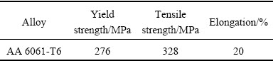
Hot rolled AA 6061-T6 aluminum alloy billet with a chemical composition as presented in Table 1 was utilized in the current work. Plates with dimensions of 300 mm �� 150 mm �� 10 mm were machined from the billets before subjecting to FSW. Mechanical properties of AA 6061-T6 are displayed in Table 2.
Table 1 Chemical composition of AA 6061-T6 aluminum alloy (wt.%)
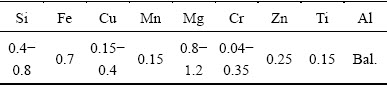
Table 2 Mechanical properties of base material
All FSW processes were carried out using tools made of the H13 tool steel. There are seven different profiles on the tools, i.e. straight cylindrical pin (SCP), threaded cylindrical pin (TCP) and tapered threaded pin (TTP) with concave parabola smooth surface shoulder, tapered threaded pin with the concentric-circles-flute shoulder (TTC) as well as three-spiral-flute shoulder (TTS), triflat threaded pin with non-flanged (FTS) and flanged (FTSF) three-spiral-flute shoulder as schematized in Fig. 1.
Thereinto, the diameter of the cylindrical pin is 6 mm. As for the tapered tool pin, the diameters of pin root and pin tip were 6 and 3 mm, respectively. The screw groove of pin is 1 mm in width and 0.5 mm in depth. The flange on the shoulder of FTSF is 1 mm in width and 0.2 mm in height. The diameter of tool shoulder is 18 mm and the depth of flute on shoulder is 0.5 mm. The length of tool pin is 3.5 mm.
Defect is easy to form in weld produced by inappropriate welding parameters [12]. To make defect- free joints with the above-mentioned tools, the welding parameters in this investigation were selected based on our previous FSW experiments and given in Table 3. To verify the effect of pass on the heat and spindle torque produced during FSW, the 2-pass FSW was carried out in an overlapping fashion, but the length was 110 mm shorter than that of the 1-pass.
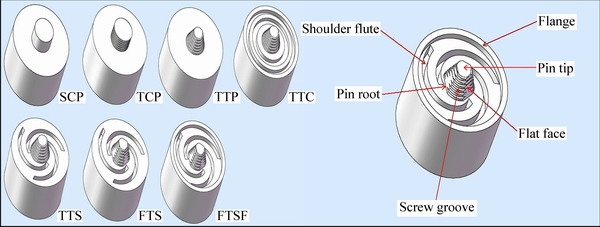
Fig. 1 Profiles of tool used for FSW
Table 3 Processing parameters during FSW

Thermal cycle was measured by K-type thermocouples that were selected in accordance with a sensitivity of approximately 41 ��V/��C and -200 to 1350 ��C range (manufacturer specifications). The temperature measurement error is within ��5 ��C via temperature calibration. Each of AA6061 plates was drilled 10 blind holes from bottom surface with a varied depth and 4 mm in diameter, as depicted in Fig. 2. Thermocouples were fixed in the bottom of these holes labeled in the sequence of their position and depth. Specifically, C, H, A and R identified the central line, heat affected zone (HAZ), advancing side (AS) and retreating side (RS), respectively. The centers of holes were positioned at 0, 15 and ��7 mm from the welding central line. The temperature data of points were recorded by a customized data acquisition system during welding. The processed plates were naturally cooled down to room temperature between each pass to eliminate the heat accumulating effect.
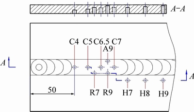
Fig. 2 Schematics of thermocouple position
Sampling positions for metallographic and tensile samples are shown in Fig. 3. Metallographic samples with dimensions of 40 mm �� 10 mm �� 10 mm were excised perpendicular to the welding direction using wire electrical discharge machining (WEDM). The samples were ground as per ASTM E407-09 guidelines and further polished in a disc machine with 1-0.5 ��m diamond. Standard Keller��s reagent was used as etching agent. XJP-6A type inverted metallographic microscope was employed to observe the macrostructure and microstructure of these samples.
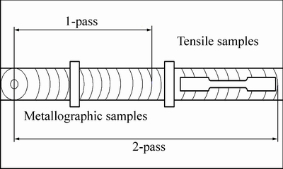
Fig. 3 Sampling position of macroscopic and tensile samples
A tensile test was carried out using a universal testing machine (UTM) as per the ASTM E8-M04 guidelines. Standard tensile samples were prepared to evaluate the tensile properties including the 0.2% offset yield strength (0.2%YS), ultimate tensile strength (UTS) and elongation in the SZ. The configuration and size of the tensile samples are shown in Fig. 4. The gauge length of the tensile sample is 25 mm. Features of fracture were characterized by scanning electron microscopy.
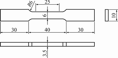
Fig. 4 Dimension of tensile samples (Unit: mm)
3 Results and discussion
3.1 Thermal cycle analysis
The peak temperatures of feature points during 1-pass and 2-pass FSW with SCP tool are listed in Table 4. For points at AS, RS and central line, the peak temperatures of 1-pass were higher than those of the 2-pass over 25 ��C, which may be explained by the microstructural softening of partial material during 1-pass. It is noted that the average sizes of participates in the SZ were smaller than those in the base material due to the breakup and dissolution effect from severe deformation and high temperature produced during 1-pass FSW. Meanwhile, the density of dislocations was decreased due to dynamic recrystallization (DRX) [13,14].
Table 4 Peak temperature (Tp) of feature points during 1-pass and 2-pass FSW with SCP tool
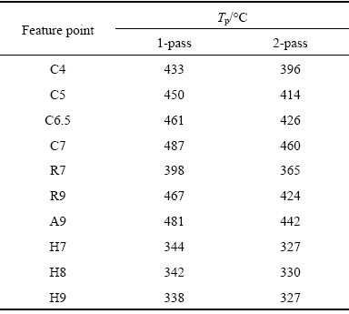
The combined effects resulted in the decrease of deformation resistance, thereby lowering the deformation heat generation during the 2-pass. However, a relatively slight peak temperature difference was observed among the points of H7, H8 and H9, which belonged to the HAZ that only experienced the thermal exposure.
The resulting peak temperatures in the AS were higher than those of RS in varying degrees except TTS tool, as displayed in Table 5. This behavior could be attributed to the material on the AS, which shows higher total linear velocities of the tool perimeter, thereby generating more heat than that of the RS during FSW [15]. It can be concluded that the heat distribution of both sides is strongly associated with the shoulder and pin geometries. The temperatures at points A9 and R9 of SCP, TCP and TTP indicated that the screw grooves on pin and tapered shape of pin resulted into lower temperature. Temperatures at point A9 of TTP, TTC and TTS implied that flutes on shoulder surface could reduce the temperature of AS in SZ. The alteration of temperatures at points A9 and R9 with TTS and FTS illustrated that triflat on pin had larger influence on the temperature of AS than three spiral flutes on shoulder surface. Note that temperature gaps between the two sides will determine the amount of localized heat treatment that occurs and influence the strength of welds that fail in the HAZ [16].
Table 5 Peak temperature of feature points on AS and RS during 1-pass FSW with seven tools
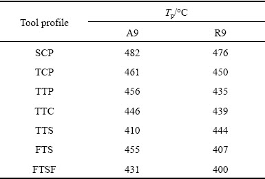
Figure 5 displays temperature history at the points R7, H7 and C7 with different tool shoulder geometries, i.e. FTS and FTSF. The peak temperature and time duration above 400 ��C at point C7 with FTS were similar to those with FTSF. However, the Tp at point R7 generated by FTS was slightly higher than that by FTSF. Moreover, the peak temperature difference between points R7 and H7 with FTSF tool was larger than that with FTS. These results indicated that the flange around tool shoulder plays a minor role in the temperature of SZ, but has a certain extent effect on the temperature of HAZ due to the diameter reduction of shoulder resulted from flange. Nevertheless, the peak temperatures at point H7 with both tools are lower than 325 ��C, implying that variation of microstructure and properties in HAZ was unconspicuous [17-19]. The main effect of flange is to prevent the material beneath tool shoulder from escaping and forming flash.
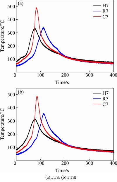
Fig. 5 Temperature history of points R7, H7 and C7 with different shoulder geometries
Figure 6 shows the comparisons of temperature measurements at points C4, C5, C6.5 and C7 with different tool pin profiles. A detailed examination in Fig. 6 reveals the following observations. Firstly, integrating with Figs. 6(a) and (b), SCP exhibited somewhat higher peak temperature at four points compared to that of TCP, which may attribute to the effect of screw grooves on pin to reduce the resistance of material around pin to flow. Secondly, since the tapered pin angle facilitates plastic material flow in SZ to form a cycle between pin tip and shoulder [20], TTP showed less obvious temperature difference in Fig. 6(c). However, FTS presented the largest temperature gradient with the highest temperature of 493 ��C at point C7 and the lowest temperature of 394 ��C at point C4 compared with SCP, TCP and TTP tools in the direction of workpiece thickness as shown in Fig. 6. Flat faces on pin lateral surface produced a pulsating stirring action in the flowing material during welding, which resulted into higher Tp at point C7. Nonetheless, these flat faces also reduced the contacted area of pin tip with workpiece. As a result, the heat of SZ was hindered to continuously transfer to the material under pin tip, which brought about the largest temperature gradient.
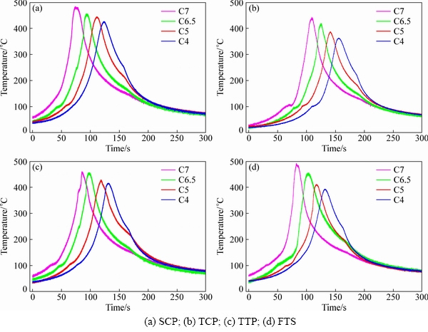
Fig. 6 Temperature history of points C4, C5, C6.5 and C7 with different tools
3.2 Tool spindle torque
Tool spindle torque of the TCP tool vs time during 1-pass and 2-pass FSW is illustrated in Fig. 7. The tool torque curve evolution can be divided into the plunging stage (0-35 s) and the dwelling stage (35-45 s) before the stable welding begins. It is clear that the tool torque experienced a severe variation with two maximum values during the two stages. Particularly, the first peak torque occurred when the pin inserted about 1/5 of its own length, but a second maximum torque appeared at the moment the shoulder contacted with workpiece [21]. From torque responses of two passes, the decrease of the first peak torque resulted from the pin between 1-pass and 2-pass was larger than that of the second torque peak resulted from shoulder. At the end of plunge, the tool dwelt for 10 s and the torque continued to drop due to further softening of the surrounding materials around the tool [22]. As the tool began to traverse forward, 1-pass tool spindle torque rose again and a relatively stable stage of torque reached. In contrast, there was a gradual decrease of tool spindle torque during 2-pass before the stable welding stage. As a consequence, the averaged tool spindle torque of 1-pass was about 8 N��m higher than that of 2-pass.
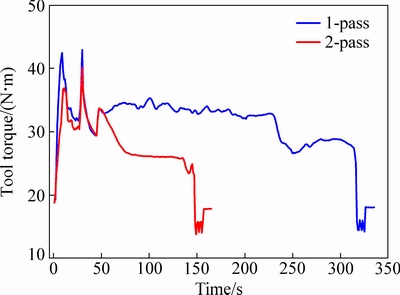
Fig. 7 1-pass and 2-pass tool spindle torque curves of TCP
The resistant forces of tool rotation changed abruptly both at the instant of pin tip contacting with workpiece and shoulder contacting with workpiece. The emergence of tool peak torque may be attributed to the effect of inertia. The workpiece used in this work was hot rolled 6061-T6 aluminum alloy plate. It owned relatively high strength and deforming resistant force than the FSW beam due to the softening effect of dynamic recrystallization during FSW. Furthermore, the temperature of workpiece was at the room temperature before pin tip contacted with workpiece. The temperature of workpiece had been raised by the heat generated from the interaction between the pin and workpiece when shoulder contacted with workpiece. Thus, the decrease of the first torque peak resulted from pin between 1-pass and 2-pass was larger than that of the second peak torque resulted from shoulder. In addition, according to the 1- and 2-pass thermal cycle results in section 3.1 and Eq. (1) in Ref. [23]:
 (1)
(1)
where W is the rate of heat generation, �� is the angular velocity of the tool, M is the tool spindle torque, the corresponding units are W, N��m, Rad/s, respectively. A negative correlation is evident between the passes.
Figure 8(a) presents 1-pass tool spindle torque curves of smooth shoulder (TTP), three-spiral-flute (TTS) and concentric-circles-flute shoulder (TTC) tool registered at identical processing parameters. During plunging stage, the tool spindle torque evolution curves of the TTP and TTS are highly consistent, the second peak torque is significantly higher than that of the first one. However, compared with two other shoulders, the lowest shoulder affected torque at the value of 38.4 N��m occurred when the TTC worked, which agrees well with the findings that concentric-circles-flute shoulder shows the relatively high flow velocity of material and low tool/workpiece rotational resistance [24]. It is worth noting that there was not such an obvious peak torque registered when the triflat pin tools (FTS and FTSF) worked during plunging stage, as illustrated in Fig. 8(b). The reason for this phenomenon is that triflat pin provided sufficient heat to soften the material around the tool before the shoulder fully contacted with it. It can also be observed that the flute and flange on shoulder had a minor influence on the tool spindle torque during stable welding stage.
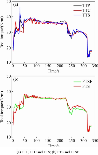
Fig. 8 1-pass tool spindle torque curves with different shoulder geometries
Figure 9 demonstrates 1-pass tool spindle torque curves of TCP and TTP. For the first peak torque affected by the tool pin, the torque of TCP tool is apparently higher than that of TTP tool due to the larger contact area between TCP pin tip and workpiece. However, the averaged torque of TTP is about 1.2 times as high as that of TCP during stable welding stage, which is in good agreement with the tool spindle torque calculated by Eqs. (2) and (3) cited from Ref. [23], the tool pin spindle torque can be written as
 (2)
(2)
 (3)
(3)
where M is the torque of pin, �� is the taper angle of pin, �� is the frictional coefficient, P is the uniform pressure acting on the pin, R2 is the radius of pin root, R3 is the radius of pin tip and H is the length of pin.
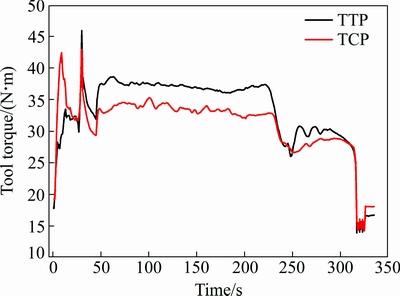
Fig. 9 1-pass tool spindle torque curves of different pin profiles
3.3 Macrostructure
Figure 10 shows the 1-pass and 2-pass macrographs of the weld transverse section fabricated by TCP and FTS. Transverse section of the corresponding weld zones along the boundary features an approximately straw hat shaped form and parabolic-shaped form, respectively. Previous researchers indicated that high strength stemmed from larger SZ size [25,26]. In the case of the tool, as illustrated in Figs. 10(a) and (c), maximum SZ depth of 1-pass sample fabricated by TCP (5.11 mm) is larger than that created by FTS (5.08 mm) since contact area of TCP pin tip with workpiece is approximately four times larger than that of FTS. In other words, the larger pin tip area of TCP drove more material under pin tip to flow and then it led to the deeper SZ. Another important feature observed in the 1-pass joints is that the upper layer width of SZ area formed by FTS (19.05 mm) is larger than that created by TCP (17.12 mm). The difference could be attributed to the material flow that was intensified by the spiral flutes on shoulder. In the case of the pass, Fig. 10(b) shows larger SZ area in the 2-pass samples compared with that of 1-pass in Fig. 10(a) due to the increasing penetration depth of TCP tool. For FTS tool, asymmetrical weld zone of the 1-pass samples in Fig. 10(c), caused by the difference of plastic deformation in the AS and RS, was modified to be nearly symmetric in Fig. 10(d) after 2-pass FSW by means of additional shearing and stirring action of FTS tool.
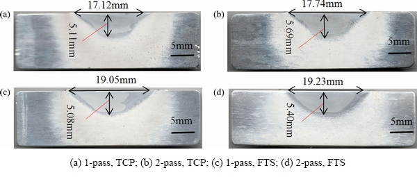
Fig. 10 Transverse sectional macrographs of FSW samples
3.4 Microstructure
The 1-pass microstructure in various regions of SZ formed by SCP, TCP, TTC and FTS are shown in Fig. 11. It is noted that grain morphology and size changed a lot due to different tool profiles. The grains produced by SCP own the largest average size among those produced by other tools, which further verified that the duration time over 400 ��C in SZ via SCP is the longest as shown in Fig. 6. The grains in the top of AS formed with tools except FTS have alike appearance, but the size of grains via TTC is more uniform. As the top of AS in SZ belongs to the shoulder affected zone, relative uniform grains produced by TTC indicate that the circle flutes on the shoulder surface could prompt the material in the top of SZ to flow uniformly. The great grain size variation in the top of AS gained by FTS demonstrated that the spiral flutes on the shoulder surface had brought about violent but uneven stir to the material in the top of SZ due to its cut effect on material. Furthermore, the low temperature caused by the spiral flute as shown in Fig. 6 also depressed the growth of grains. The materials in center and bottom of SZ were mainly stirred by tool pin. Then, the microstructure of these regions is dominantly controlled by pin profile. It can be observed from Fig. 11 that the morphology and size of grains in center and bottom of SZ were affected by the pin profile seriously. The grains in the center and bottom of SZ via SCP have similar morphology and size. Whereas, grains in the center of SZ via TCP are completely different from those in bottom, indicating that the screw groove on pin could accelerate the materials around pin to flow along circumferential direction but generate less heat, which can be proved by Fig. 6(b). Meanwhile, the heterogeneous microstructure of SZ along workpiece thickness direction elucidates that cylindrical pin had no effect on the materials around pin flowing along pin length. The similar microstructure in center and bottom of SZ via TTC implies that the tapered shape pin can facilitate the material around pin flow along pin length. Compared with the grains in SZ central region via TTC, the grains in SZ central region via FTS possess larger size, which may be attributed to severe material plastic deformation and more heat generation resulted from flat faces on pin. Furthermore, the difference in grain size between center and bottom region via FTS explains the temperature gradient caused by flat faces on pin too.
Figure 12 displays the 1-pass microstructure of TMAZ on AS with different tools. The feature of TMAZ varied with pin profile. As for tools except TCP, there are obvious recrystallized grains in TMAZ on the side next to SZ. At the interface between TMAZ and HAZ of SCP as pointed by arrow A, the large HAZ grain was cut without deformation. Whereas, HAZ grains of TTC and FTS were bent abruptly at the interface between TMAZ and HAZ as pointed by arrows E and F. The large grains in TMAZ of TCP were reoriented to the direction parallel to interface between SZ and TMAZ with a small amount of recrystallized grains as pointed by arrows B and C. These results manifest that screw grooves on pin could promote the material around pin to deform and reduce heat generation.
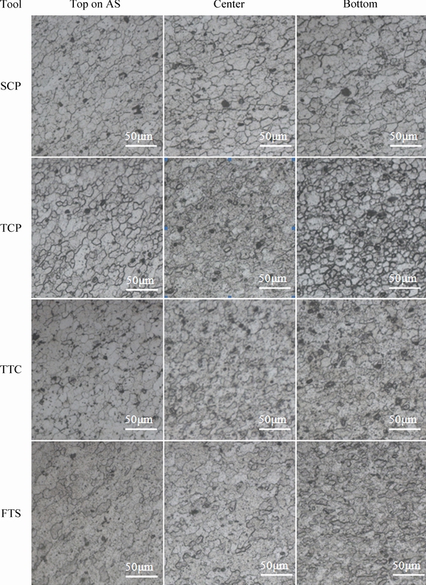
Fig. 11 1-pass microstructures in various regions of SZ formed by different tools
3.5 Mechanical properties
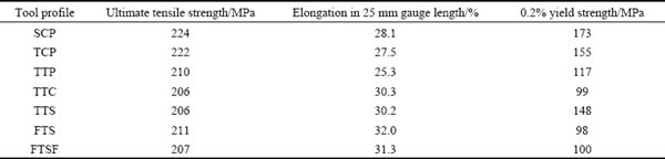
The main tensile test results of samples taken from SZ are listed in Table 6. Overall, it is evident that the mean UTS and 0.2% YS were dramatically decreased due to the fact that the density of dislocations was reduced by DRX [27], whereas the elongation was increased after 1-pass FSW. Of the seven joints fabricated by different tools, the joint formed by SCP tool exhibited the highest ultimate tensile strength of 224 MPa which was equivalent to 68.3% of UTS of the base material. A relatively low 0.2% YS and high elongation characterized the joints produced by triflat tools compared to other tools. However, the maximum elongation belonged to FTS sample.
Fracture behaviors of tensile samples with typical mechanical properties were analyzed in detail through SEM. All fractured samples revealed necking phenomenon more or less, fibrous by the naked eye, the color gray at low magnification as shown in Figs. 13(b), (d) and (f). Fracture surfaces of tensile samples are a dimple pattern with features of ductile fracture. Dimples oriented towards the loading direction are highly variable in size and distribution. SCP shows larger and deeper dimples in Fig. 13(a), which are uniformly distributed since large second phase particles were pulled out under high stress and strain levels. Some cracked particles can be seen at the bottom of dimples (white arrow), which was responsible for its higher UTS and YS. TTP shows a low ductility fracture with the dimple-free region as shown in Fig. 13(c). Considering its lowest elongation, the presence of segregated dimples (white arrow) and dimple-free regions (white ellipse) on the fracture surface seems to have an adverse influence on the total ductility. Figure 13(e) shows the whole fracture surface of FTS sample that is covered with dense near-equiaxed dimples, signifying its relatively high elongation [28]. The corresponding cross-section transformed from a regular square to a local shrinking shape as shown in Fig. 13(f). The high temperature and severe plastic deformation caused by the FTS could result in the dissolution and breakup of second phase particles, which did not inhibit the dislocation motion strongly and in turn yield strength was decreased [27]. Finer grains caused by pulsating action of FTS contributed to the improvement of elongation.
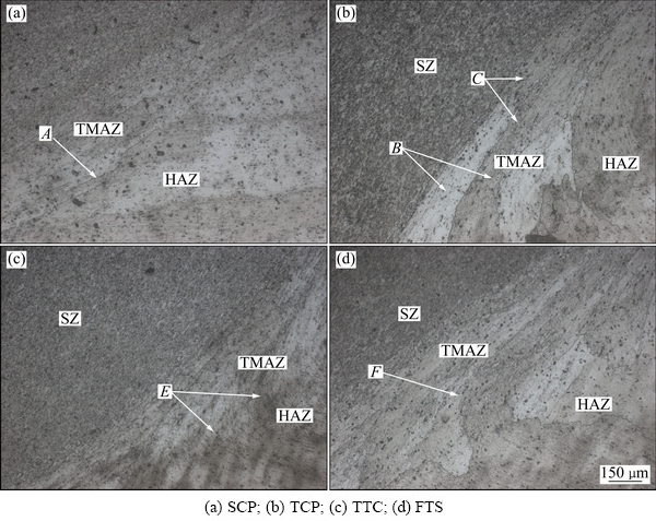
Fig. 12 1-pass microstructures of TMAZ (thermo-mechanical affected zone) on AS with different tools
Table 6 Mechanical properties of welded samples
4 Conclusions
(1) Tool profiles played a key role in the thermal cycle. Screw groove on pin reduced the temperature in SZ. Flat face on pin increased the temperature and temperature gradient along pin length direction in SZ. Flute on the surface of shoulder reduced the temperature of AS in SZ. Tapered shape of pin decreased the temperature gradient along pin length in SZ. Tool with triflat tapered thread pin and three spiral flutes shoulder show the highest temperature in SZ and the largest temperature gradient in the direction of workpiece thickness. The flange around shoulder had little effect on the temperature of SZ.
(2) There were peak torques resulted from tool pin tip and shoulder during plunging stage. The peak torque decreased with the decrease of contact area between pin tip and workpiece. The circle flutes on shoulder and flat face on pin reduced the peak torque caused by the contact of shoulder with workpiece. TCP tool had relatively low tool torque at the steady stage. A negative correlation between passes was attained as the tool torque response.
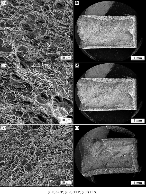
Fig. 13 High and low magnification fractographs of fractured samples
(3) Microstructure of FSW joint was affected by tool profile. SCP tool resulted into the largest grains in SZ and large HAZ grains cut at the interface of TMAZ and HAZ. Circle flutes on shoulder were beneficial for the homogenization of recrystallized grains in the top of SZ. Spiral flutes on shoulder enlarged the top of SZ width and depressed recrystallized grains in the top of SZ to grow. Screw grooves on pin prevent grains in SZ from growing and promoted the reorientation of grains in TMAZ. Flat faces on pin increased the inhomogeneity of SZ grain size. Tapered shaped pin led to the uniformation of grains in SZ along pin length. The inhomogeneity of SZ microstructure caused by tool profile in the first pass was improved by the second pass.
(4) Straight cylindrical pin (SCP) tool exhibited the highest ultimate tensile strength of 224 MPa. However, the maximum elongation of 32.0% belonged to non-flanged triflat tool (FTS). A relatively high 0.2% YS was obtained for joints produced by tools of shoulder without flutes.
Acknowledgments
The authors gratefully acknowledge the financial support from the Independent Innovation Plan of Colleges and Universities in Ji��nan and the Scientific Research Foundation for the Returned Overseas Chinese Scholars, State Education Ministry. The authors also thank song GAO and zhen SUN for providing the experimental instruction in this investigation.
References
[1] Thomas W M, Nicholas E D, NeedHam J C, Murch, M G, Templesmith P, Dawes C J. Friction stir butt welding: International patent application No. PCT/GB92102203 and Great Britain patent application, No. 9125978.8 [P]. 1991-12-01.
[2] Mishra R S, Ma Z Y. Friction stir welding and processing [J]. Materials Science and Engineering R, 2005, 50: 1-78.
[3] BHATT K D, PILLAI B. Simulation of peak temperature & flow stresses during friction stir welding of AA7050-T7451 aluminum alloy using hyper works [J]. International Journal of Emerging Technology and Advanced Engineering, 2012, 2(5): 212-216.
[4] ZHANG Z, QI W U, ZHANG H W. Numerical studies of effect of tool sizes and pin shapes on friction stir welding of AA2024-T3 alloy [J]. Transactions of Nonferrous Metals Society of China 2014, 24(10): 3293-3301.
[5] HATTINGH D G, BLIGNAULT C, van NIEKERK T I, JAMES M N. Characterization of the influences of FSW tool geometry on welding forces and weld tensile strength using an instrumented tool [J]. Journal of Materials Processing and Technology, 2008, 203(1): 46-57.
[6] ELANGOVAN K, BALASUBRAMANIAN V. Influences of tool pin profile and welding speed on the formation of friction stir processing zone in AA2219 aluminum alloy [J]. Journal of Materials Processing and Technology, 2008, 200(1): 163-175.
[7] Mehta K P, Badheka V J. Influence of tool pin design on properties of dissimilar copper to aluminum friction stir welding [J]. Transactions of Nonferrous Metals Society of China, 2017, 27(1): 36-54.
[8] KADIAN A K, BISWAS P. Effect of tool pin profile on the material flow characteristics of AA6061 [J]. Journal of Manufacturing Processes, 2017, 26: 3 82-392.
[9] BUFFA G, CAMPANILE G, FRATINI L, PRISC A. Friction stir welding of lap joints: Influence of process parameters on the metallurgical and mechanical properties [J]. Materials Science and Engineering A, 2009, 519(1): 19-26.
[10] KHODAVERdIZADEH H, MAHMOUDI A, HEIDARZADEH A, NAZARI E. Effect of friction stir welding (FSW) parameters on strain hardening behavior of pure copper joints [J]. Materials & Design, 2012, 35: 330-334.
[11] TRUEBA L, HEREDIA G, RYBICKI D, JOHANNES L B. Effect of tool shoulder features on defects and tensile properties of friction stir welded aluminum 6061-T6 [J]. Journal of Materials Processing and Technology, 2015, 219: 271-277.
[12] MENDES N, LOUREIRO A, MARTINS C, NETO P, PIRES J N. Effect of friction stir welding parameters on morphology and strength of acrylonitrile butadiene styrene plate welds [J]. Materials & Design, 2014, 58: 457-464.
[13] KRASNOWSKI K, HAMILTON C, DYMEK S. Influence of the tool shape and weld configuration on microstructure and mechanical properties of the Al 6082 alloy FSW joints [J]. Archives of Civil and Mechanical Engineering, 2015, 15(1): 133-141.
[14] SU J Q, NELSON T W, STERLING C J. Microstructure evolution during FSW/FSP of high strength aluminum alloys [J]. Materials Science and Engineering A, 2005, 405(1-2): 277-286.
[15] ADAMOWSKI J, SZKODO M. Friction stir welds (FSW) of aluminum alloy AW6082-T6 [J]. Journal of Achievements in Materials and Manufacturing Engineering, 2007, 20(1-2): 403-406.
[16] COLE E G, FEHRENBACHER A, DUFFIE N A, ZINN M R, PFEFFERKORN F E, FERRIER N J. Weld temperature effects during friction stir welding of dissimilar aluminum alloys 6061-T6 and 7075-T6 [J]. International Journal of Advanced Manufacturing Technology, 2014, 71(1-4): 643-652.
[17] LIU F C, MA Z Y. Influence of tool dimension and welding parameters on microstructure and mechanical properties of friction-stir-welded 6061-T651 aluminum alloy [J]. Metal Mater trans A, 2008, 39(10): 2378-2388.
[18] MERTIN C, NAUMOV A, MOSECKER L, Bambach M, Hirt G. Influence of the process temperature on the properties of friction stir welded blanks made of mild steel and aluminum[C]//Key Engineering Materials. Switzerland: Trans Tech Publications, 2014: 1429-1436.
[19] WANG T. Effect of friction stir welding parameters on the microstructure and properties of 6061-T6 aging hardenable aluminum alloy [D]. Ji��nan: Shandong University, 2018. (in Chinese)
[20] JIN Y Y. Material transfer behavior during the process of friction stir welding [D]. Shenyang: Shenyang Aerospace University, 2013. (in Chinese)
[21] LONGHURST W R, STRAUSS A M, COOK G E, FLEMING P A. Torque control of friction stir welding for manufacturing and automation [J]. International Journal of Advanced Manufacturing Technology, 2010, 51(9): 905-913.
[22] SU H, WU C S, PITTNER A, RETHMEIER M. Simultaneous measurement of tool torque, traverse force and axial force in friction stir welding [J]. Journal of Manufacturing Processes, 2013, 15(4): 495-500.
[23] WANG G Q, ZHAO Y H. The friction stir welding of Aluminum alloy [M]. Beijing: China Astronautic Publishing House, 2010. (in Chinese)
[24] JI S D, SHI Q Y, ZHANG L G, ZOU A L, GAO S S, ZAN L V. Numerical simulation of material flow behavior of friction stir welding influenced by rotational tool geometry [J]. Computational Materials Science, 2012, 63: 218-226.
[25] PAIDAR M, SADEGHI F, NAJAFI H, KHODABANDEH A R. Effect of pin and shoulder geometry on stir zone and mechanical properties of friction stir spot-welded aluminum alloy 2024-T3 sheets [J]. Journal of Engineering Materials and Technology, 2015, 137: 031004-1.
[26] Rajakumar S, Muralidharan C, Balasubramanian V. Establishing empirical relationships to predict grain size and tensile strength of friction stir welded AA 6061-T6 aluminum alloy joints [J]. Transactions of Nonferrous Metals Society of China, 2010, 20(10): 1863-1872.
[27] HAO H L, NI D R, ZHANG Z, WANG D, XIAO B L, MA Z Y. Microstructure and mechanical properties of Al�CMg�CEr sheets jointed by friction stir welding [J]. Materials & Design, 2013, 52: 706-712.
[28] ZHANG Z, YANG R, GUO Y, CHEN G, LEI Y, CHENG Y, Yue Y. Microstructural evolution and mechanical properties of ZrB2/6061Al nanocomposites processed by multi-pass friction stir processing [J]. Materials Science and Engineering A, 2017, 689: 411-418.
�� ��1�������1��������1���γ�Ⱥ2
1. ɽ����ѧ ����Һ�̽ṹ�ݱ���ӹ��������ص�ʵ���ң����� 250061��
2. ��������ҵ��ѧ �Ƚ����������ӹ����ص�ʵ���ң������� 150001
ժ Ҫ���о�����Ħ����(FSW)�����н���ͷ��״��AA6061-T6���������ͷ����������õ�Ӱ�졣FSW�ӹ������У����ö��Ƶ�ʵ��װ����ɶ��������¶Ⱥͽ���ͷ����Ť�صIJ�����ͬʱ�Խ�����(SZ)����֯���������ܽ��б�����������������ͽ�������״�ֱ�Ӱ��������IJ��ȡ�����ν���ͷŤ�غͽ������������״������ϵİ��ۺͽ������ϵ�����ʹ�������еľ�������ϸ�����������ϵ���ƽ�����²����ȵľ����ߴ硣����Բ���ν�����Ľ���ͷ���Եõ�0.2%����ǿ��Ϊ173 MPa�ĺ��죬��������ƽ�������ν�����Ľ���ͷ���Եõ��쳤��32.0%�ĺ��졣
�ؼ��ʣ�����Ħ����������ͷ���Σ���ѭ��������ͷ����Ť�أ���������
(Edited by Xiang-qun LI)
Corresponding author: Rui-jun BAO; Tel: +86-18366113716; E-mail: baozibufan@126.com
DOI: 10.1016/S1003-6326(19)64958-7

