Trans. Nonferrous Met. Soc. China 24(2014) 2387-2392
A new hole-flanging method for thick plate by upsetting process
Qi-quan LIN1, Wen-zheng DONG1, Zhi-gang WANG2, Katsuyoshi HIRASAWA2
1. School of Mechanical Engineering, Xiangtan University, Xiangtan 411105, China;
2. Department of Mechanical Systerms Engineering, Gifu University, Gifu 501-1193, Japan
Received 17 October 2013; accepted 29 April 2014
Abstract: Flange height and lip accuracy are generally restricted by the formability of sheet metals in the conventional hole-flanging operation. A new hole-flanging process, named upsetting-flanging process, was proposed to obtain a more substantial flange from thick plate. The finite element method (FEM) with DEFORM was utilized to simulate the novel upsetting-flanging process and the influence of geometric parameters on the flange height was studied in details. A series of flanging experiments with A1050P-O were carried out to validate the FEM results, and the variations of Vicker hardness in the plate section were discussed. The results showed that the newly upsetting-flanging process revealed higher flange height and better lip accuracy than the conventional hole-flanging process, and the results between FEM simulations and experiments showed good agreement. Besides, the hardness of the plate around the flange part increases due to the work hardening after the upsetting-flanging process, which reveals better superiority in strength for the subsequent machining or assembling processes.
Key words: upsetting-flanging; flange height; FEM; thick plate; A1050 aluminum alloy; hardness
1 Introduction
Hole-flanging is a process widely used in press working of sheet metal. In conventional hole-flanging, a flat sheet with a pre-cut hole is formed as the punch moves down against a die so as to produce a smooth, round flanged lip with higher strength. However, flange height and lip thickness are generally restricted by the formability of sheet metals in the conventional hole-flanging operation [1-3]. Especially for the thick plate, forming defects such as fracturing, thinning or shrinking can easily occur on the wall of the flange, resulting in workpiece unsuitable for subsequent machining or assembling.
Generally, when a longer flange or a better finished lip is needed, ironing is utilized. KUMAGAI et al [4,5] discussed the influence of the plate thickness on the punch load, the finished shape and the metal flow in the hole-flanging with the ironing of thick sheet metal. THIPPRAKMAS et al [6] performed the hole-flanging with ironing for thick sheet metal to study the effect of the quality of the initial hole on the flanged shape. According to work of KACEM et al [7,8], the effect of the clearance-to-thickness ratio on the hole-flanging process was investigated to determine the occurrence of ironing. However, the seizure defect cannot be avoided due to the high surface expansion and severe tribological conditions at the contact between the punch and the inner wall during the hole-flanging process with ironing, as reported in previous studies [4,9,10]. Thus, other techniques should be proposed to produce a long flange. On one hand, LIN et al [11,12] applied the cold extrusion to obtaining a more substantial flange with a lower diameter. In this case, the flange was formed by exerting a punch force on the rim of a pre-holed cup-shaped workpiece at the same time as a clamping force was applied to suppressing dilation on the bottom of the cup. On the other hand, incremental forming had been adopted for a longer lip which was an emerging process with a high potential economic payoff for rapid prototyping and for small quantity production, as shown in the work of the previous literatures [13-16].
In the present work, a novel hole-flanging process, named upsetting-flanging process, was proposed to obtain a more substantial flange from thick plate. The finite element method (FEM) with DEFORM was utilized to simulate the novel upsetting-flanging process and the influence of geometric parameters on the flange height was studied in details.
2 Upsetting-flanging process
2.1 Principle of upsetting-flanging process
To obtain a successful flange, the novel upsetting- flanging process will be distributed into three stages: upsetting, flanging and shaping, as shown in Fig. 1. Firstly, the workpiece is held with the blank holder and the upsetting process is performed by lowering the upsetting punch, as shown in Fig. 1(a). An arresting ring is positioned to prevent the material from flowing toward the outer edge, and a taper is designed on the lower blank holder to promote greater flow of material toward the hole side. Figure 1(b) shows the flanging process performed by pushing the flanging punch upwards. Finally, the flange is shaped by pushing down the sleeve punch, as shown in Fig. 1(c).
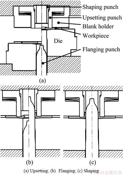
Fig. 1 Principle of upsetting-flanging process
2.2 FEM simulation setup
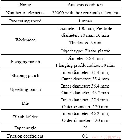
In this study, a commercial analytical code for statistic implicit finite element method (DEFORM) was used as the FEM simulation tool. Due to symmetry, only a quarter of the simulation model was used to reduce the calculated time, as shown in Fig. 2. The automatic remeshing was set at every five steps to prevent a divergence calculation. The blanked material was assumed to be elasto-plastic type with the rectangular element of approximately 30000 elements, and the tools (die, punch and blank-holder) were modeled as rigid ones, as shown in Table 1. Two geometric parameters were taken into consideration, the pre-hole diameter, D, and the width of shaping punch, L, which play an important role in the flanging formability, as shown in Fig. 2.
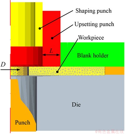
Fig. 2 FEM model of upsetting-flanging process
Table 1 FEM simulation conditions
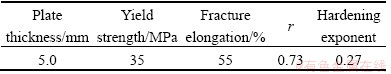
The hot-rolled A1050P-O(JIS) aluminum sheet was used as the workpiece material, and its constitutive equation was determined from the stress-strain curve obtained by the tensile testing experiment, as shown in Table 2. The tensile strength and strain hardening exponent values were 77 MPa and 0.27, respectively.
Table 2 Mechanical properties of hot-rolled A1050P-O(JIS) aluminum sheet
3 Results and discussion
3.1 Process parameters analysis
Figure 3 shows the relationships between the upsetting height (s), flange height (h), hole inside diameter (d) and plate thickness around the hole (t). As the upsetting height increases, the thicker the plate is, the smaller the hole diameter becomes, and the sheet material around the hole is pushed upward as well. Thus, during the upsetting process, more sheet materials are piled up for the following flange part. When the upsetting height exceeds 1.8 mm, both the hole diameter and the plate thickness reveal a small change; however, the flange height increases directly.
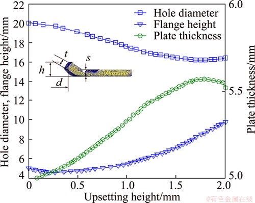
Fig. 3 Variations in plate thickness, hole diameter and flange height with upsetting height
In the upsetting-flanging process, a taper structure is designed on the lower blank holder so as to promote a greater flow of the material toward the hole side. Figure 4 illustrates the influence of taper angle on the flange height and the maximum load after the upsetting- flanging process. Obviously, as the taper angle increases, the compressed material flows into the flange more easily, so that the maximum load greatly decreases. Besides, the flange height gradually reduces because the workpiece volume decreases at the taper portion. To obtain a higher flange under the lowest processing load, an appropriate taper angle should be carefully designed.
3.2 Variations of hoop strain
To demonstrate the variations of hoop strain in flanging process, four different flanging conditions are investigated, as shown in Fig. 5. In the case of the conventional hole-flanging process (D=16 mm, L=0 mm), the hoop strain exceeds 1.0 and cracks appear on the flange’s edge. In the case of the upsetting-flanging process, under all conditions, the hoop strain becomes negative (which refers to compress stress) at first and then changes to positive (which refers to tensile stress).
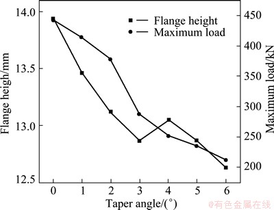
Fig. 4 Variations in taper angle, flange height and the maximum load after upsetting-flanging process (s=2 mm, L=9.8 mm)
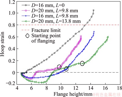
Fig. 5 Relationship between flange height and hoop strain of flange edge
And no cracks can be found during the flanging process since the hoop strain exceeds no more than the fracture limit. Moreover, under the same hoop strain, the flange height increases as the upsetting width increases, as shown in Fig. 5.
3.3 Experimental verification
Based on the FEM analysis, both the conventional hole-flanging and the upsetting-flanging die sets were prepared under the same conditions with FEM simulation. The thick paraffin petrolatum P460 was used as a lubricant and the diameter of the prepared hole for the flanging process was 20 mm. All the experiments were carried out on the 500 kN hydraulic oil press in our laboratory.
Figure 6 shows a cross-section of the flange after the conventional flanging process with a 5 mm aluminum plate. There are two kinds of shape defects in the flange part. One is the insufficient flange height (see Fig. 6(a)), and the other is the excessive thinning around the tip part (see Fig. 6(b)). Besides, the quality defects such as cracks on the flange edge (see Fig. 7(a)) and shrinkage (see Fig. 7(b)) can easily occur after the flanging process.

Fig. 6 Flange shape of conventional hole-flanging process
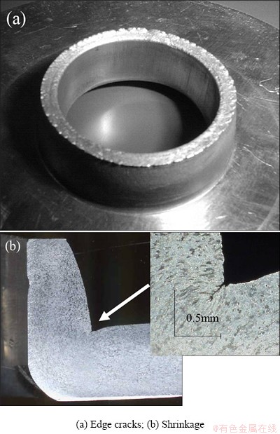
Fig. 7 Quality defects in conventional hole-flanging process
However, as shown in Fig. 8, there are no remarkable shape defects and quality defects in the upsetting-flanging process and its flange height is higher than that in the conventional hole-flanging under the same conditions. Moreover, the hardness of the plate around the flange part increases due to the work hardening after the upsetting-flanging process (see Fig. 9). As a result, the formed part reveals better superiority in strength for the subsequent machining or assembling processes. Figure 10 shows the flange shape after each forming stage in the upsetting-flanging process, and the characteristics of plate thickness and flange height show good agreement between experiments and FEM.
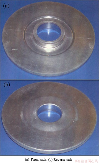
Fig. 8 Flange shape of upsetting-flanging process
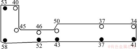
Fig. 9 Distributions of Vickers hardness in plate section (initial hardness is HV34)
4 Conclusions
1) Considering the insufficient flange height and quality defects in the conventional flanging process, a novel flanging process, named upsetting-flanging process, was proposed to obtain a more substantial flange from thick plate and no crack occurs during the upsetting-flanging process because of the negative hoop strain near the flange edge.
2) A taper structure designed on the lower blank holder plays an important role during the upsetting-flanging process, and the larger the taper angel is, the smaller the flange height and the maximum load become.
3) The hardness of the plate around the flange part increases due to the work hardening after the upsetting-flanging process, which reveals better superiority in strength for the subsequent machining or assembling processes.
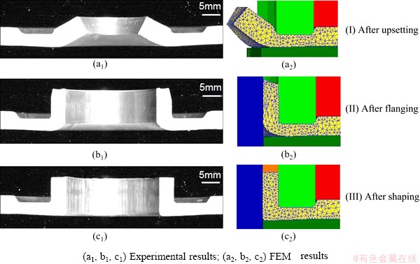
Fig. 10 Flange shapes after each forming stage during upsetting-flanging process
References
[1] JOHNSON W, CHITKARA N R, MINH H V. Deformation modes and lip fracture during hole-flanging of circular plates of anisotropic materials [J]. Journal of Engineering for Industry: Transactions of ASME, 1977, 99: 738-748.
[2] HUANG Y M, CHIEN K H. The formability limitation of the hole-flanging process [J]. Journal of Materials Processing Technology, 2001, 117: 43-51.
[3] TAKUDA H, HATTA N. Numerical analysis of formability of a commercially pure zirconium sheet in some sheet forming processes [J]. Materials Science and Engineering A, 1998, 242: 15-21.
[4] KUMAGAI T, SAIKI H. Deformation analysis of hole-flanging with ironing of thick sheet metals [J]. Metals and Materials, 1998, 4(4): 711-714.
[5] KUMAGAI T, SAIKI H, MENG Y. Hole flanging with ironing of two-ply thick sheet metals [J]. Journal of Materials Processing Technology, 1999, 89-90: 51-57.
[6] THIPPRAKMAS S, JIN M, MURAKAWA M. Study on flanged shapes in fineblanked-hole-flanging process (FB-hole-flanging process) using finite element method (FEM) [J]. Journal of Materials Processing Technology, 2007, 192-193: 128-133.
[7] KACEM A, KRICHEN A, MANACH P Y. Occurrence and effect of ironing in the hole-flanging process [J]. Journal of Materials Processing Technology, 2011, 211(10): 1603-1613.
[8] KACEM A, KRICHEN A, MANACH P Y. Characterization of ironing in the hole-flanging process of an aluminum alloy [C]//AIP Conference Proceedings. Seoul: AIP Publishing, 2011, 1383: 831-838.
[9] CAO F R, WEN J L, DING H, WANG Z D, LI Y L, GUAN R G, HOU H. Force analysis and experimental study of pure aluminum and Al-5%Ti-1%B alloy continuous expansion extrusion forming process [J]. Transactions of Nonferrous Metals Society of China, 2013, 23: 201-207.
[10] QUAN G Z, WANG F B, LIU Y Y, SHI Y, ZHOU J. Evaluation of varying ductile fracture criterion for 7075 aluminum alloy [J]. Transactions of Nonferrous Metals Society of China, 2013, 23: 749-755.
[11] LIN H S, LEE C Y, WU C H. Hole-flanging with cold extrusion on sheet metals by FE simulation [J]. International Journal of Machine Tools & Manufacture, 2007, 47: 168-174.
[12] LIN H S, TUNG C W. An investigation of cold extruding hollow flanged parts from sheet metals [J]. International Journal of Machine Tools & Manufacture, 2007, 47: 2133-2139.
[13] HAN F, MO J H, LONG R F, CUI X H, LI Z W. Springback prediction for incremental sheet forming based on FEM-PSONN technology [J]. Transactions of Nonferrous Metals Society of China, 2013, 23: 1061-1071.
[14] CENTENO G, SILVA M B, CRISTINO V A M, VALLELLANO C, MARTINS P A F. Hole-flanging by incremental sheet forming [J]. International Journal of Machine Tools & Manufacture, 2012, 59: 46-54.
[15] PETEK A, KUZMAN K, FIJAVZ R. Backward drawing of necks using incremental approach [J]. Key Engineering Materials, 2011, 473: 105-112.
[16] HALOUANI A, LI Y M, BOUSSAD A, GUO Y Q. Optimization of cold forging perform tools using pseudo inverse approach [J]. Transactions of Nonferrous Metals Society of China, 2012, 22: s207-s213.
厚板镦粗-翻边复合工艺
林启权 1,董文正 1,王志刚 2,Katsuyoshi HIRASAWA 2
1. 湘潭大学 机械工程学院,湘潭 411105;
2. Department of Mechanical Systerms Engineering, Gifu University, Gifu 501-1193, Japan
摘 要:传统圆孔翻边工艺中,翻边高度和形状精度是制约板料成形极限的主要因素。为了获得较为稳固的翻边凸起部位,提出采用镦粗-翻边复合工艺成形厚板翻边凸起结构。利用DEFORM有限元软件对镦粗-翻边复合工艺过程进行数值模拟,分析各工艺参数对翻边高度的影响规律;对A1050P-O厚板进行了镦粗-翻边工艺试验并讨论了翻边后的板料硬度分布规律。结果表明:与传统翻边工艺相比,镦粗-翻边工艺的翻边凸起部位精度更好、翻边高度更高,且有限元模拟结果与试验结果保持了较好的一致性。成形后的板料由于加工硬化影响,翻边凸起结构的硬度增大,有利于零件的后续加工组装工序。
关键词:镦粗-翻边工艺;翻边高度;有限元法;厚板;A1050合金;硬度
(Edited by Hua YANG)
Foundation item: Project (51175445) supported by the National Natural Science Foundation of China; Project (2010DFA52130) supported by the International Cooperation Project of the Ministry of Science and Technology, China; Project (CX2013B277) supported by Hunan Provincial Innovation Foundation for Postgraduate, China
Corresponding author: Qi-quan LIN; Tel: +86-13907329653; E-mail: xtulqq@126.com
DOI: 10.1016/S1003-6326(14)63361-6

