
Effects of honing treatment on AIP-TiN and TiAlN coated end-mill for high speed machining
Jae-Young HEO1, Sung-Hak CHO2, Tae-Jin JE2, Kwang-Ho KIM1, Hyung-Woo LEE1, Myung-Chang KANG1
1. National Core Research Center for Hybrid Materials Solution, Pusan National University,
Busan 609-735, Korea;
2. Nano Machining Laboratory, Korea Institute of Machinery and Material (KIMM), 171 Jang-dong,
Yuseong-Gu, Daejeon 305-343, Korea
Received 21 April 2010; accepted 10 September 2010
Abstract: The objective of this work is to compare the tool performance of TiN and TiAlN coated carbides end-mills deposited by an arc ion plating (AIP) method, using honing treatment to polish the cutting edge surface sleekly. The curve of surface roughness versus honing time showed a rapid improvement initially and thereafter became steady, manifesting a saturation effect. The optimal honing time related to surface roughness was determined to be approximately 20 s. As the surface roughness increased, the critical loads reduced. At an average surface roughness (Ra) of 0.028 mm, the highest critical loads of TiN and TiAlN coating layers were 98 and 114 N, respectively. Tool performances of uncoated and coated tools were conducted under high speed machining (HSM) of AISI D2 cold-worked die steel (62 HRC). Consequently, the TiAlN coated end-mill using honing treatment showed excellent tool life under HSM conditions.
Key words: TiAlN; arc ion plating; honing treatment; high speed machining; tool life
1 Introduction
High speed machining (HSM) process is briskly adopted in die manufacturing due to its excellent machining capabilities and superior coating materials. Although the performances of tools were improved impressively with coating materials such as TiC, TiN and Ti-Al-N[1], severe tool damages took place in machining highly hardened materials of die steel series[2].
Arc ion plating (AIP) process was one of the most perspective PVD methods for industrial manufacture because it involved a low-temperature process and a high deposition rate[3]. In addition, it was reported that TiN and TiAlN coating layers were dense and fairly adherent to WC-Co substrates[4]. However, it has not been reported yet how the honing treatment which is a sleekly polishing process impacts the surface of tools on the coating characteristics and tool performance.
In this study, TiN and TiAlN coatings were deposited onto substrates and end-mill tools made of WC-Co material by AIP technique. The XRD patterns, SEM and AFM images, micro-hardness and critical loads were investigated. Prior to deposition coating layer, surface of cutting edge were polished by honing machine and optimal conditions were determined. Cutting tests were carried out to evaluate the performances of uncoated and coated end-mill under high speed machining condition.
2 Experimental
2.1 Honing process and coating deposition
The honing processes on the substrate and cutting tool were conducted on an AERO-mirror honing machine with a spray nozzle mounted on a rotary body (Toyo, SMAP). Abrasive material was used as marchicon media of alumina series (Toyo, SP-100D). The honing conditions are presented in Table 1.
TiN and TiAlN coatings were deposited onto substrates and end-mill tools made of WC-Co material by AIP technique. The mechanical properties of WC-Co material used in this experiments were as follows: hardness of HRA 92.8, transverse rupture strength >4 000 (N/mm2), WC particle size of 0.8 μm and Co content of 10% (mass fraction). The WC-Co substrates, which were machined into disc types of d 20 mm×3 mm, were thoroughly cleaned in an ultrasonic bath cleaner with acetone and alcohol for 20 min. The disc specimens were vertically hanged in the steel rack and then placed into the vacuum chamber below the target. The purity of Ar and N2 gases used was 99.99%, and that of the Ti target and 0.67Ti-0.33Al alloy target were 99.99%. Prior to deposition, the surface of substrates was further cleaned by Ar ion bombardment for 10 min. The typical deposition conditions for TiN and TiAlN coating were summarized in Table 2.
Table 1 Honing parameters
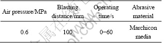
Table 2 Typical deposition parameters for TiN and TiAlN coatings using AIP technique

2.2 Coating evaluation
The crystal structure for coating layer was analyzed by X-ray diffractomety (XRD, Rigaku, D/Max-2400). The cross-sectional morphologies of both coating layers were observed by scanning electron microscopy (Hitachi, S-4200). The hardness was determined by using a microhardness tester with a Knoop indentor (Matsuzawa, MMT-7) under a load of 0.25 N. Images of tool edge were observed by CCD camera (PULNIX, TM9701). Surface roughness values of the substrate and the end-mill tool were measured by atomic force microscopy (Digital Instruments Nanoscope Шa). The adhesion behavior of both coating layers were investigated with a scratch tester (J&L Tech, JLST022) using a Rockwell C diamond stylus (cone apex angle 120°, tip radius 200 μm). During the scratch test, the stylus load increased continuously up to 150 N with a loading rate of 3 N/s and a translation speed of 0.2 mm/s. The scratch channel was observed with an optical microscope (Olympus, PMG3-613U W/Acc).
2.3 Cutting test
The experiments were carried out without any coolant in a vertical high-speed machining center (MAKINO, V-55)[5]. Tool wear was measured by a CCD camera (PULNIX, X200), which was attached to the machine. Cutting test was started with a fresh cutting tool, and the machining process was stopped at certain intervals of cutting length in order to measure the flank wear. Flank wear was obtained by the average value of three points measured on the cutting edge within axial cutting depth. The tool life obtained with flank wear of 0.2 mm was used as a criterion (ISO 3002/1) for a comparative evaluation of the TiN and TiAlN coating tools[5]. The workpiece used in the experiments was high-hardened die steel (AISI D2, HRC 62). The experimental conditions carried out under high-speed cutting are listed in Table 3.
Table 3 Cutting parameters for tool performance test

3 Results and discussion
3.1 Honing phenomenon
Fig.1 shows the CCD images and AFM images of cutting tools before deposition. The AFM images indicated that the surface morphology of cutting tool considerably depended on honing operation. The average surface roughness (RMS) of cutting tool was calculated from AFM images of selected areas of 3 μm×3 μm. The surface morphology of the coatings with no honing operation (Fig.1(b)) was found to be very rough (RMS, 0.20 μm). In the case of honing operation (Fig.1(d)), the cutting tool had a greatly smooth surface morphology (RMS, 0.07 μm), which was due to the roughness improvement of the tool edge surface.
Fig.2 shows the curves of surface roughness of cutting tool versus honing time. The honing curves showed a rapid improvement initially and thereafter the surface roughness became steady at honing time of 20 s, manifesting a saturation effect. Familiar knees in honing curves were reported earlier by PARKS et al[6] and YU et al[7]. The optimal honing time under given honing conditions was determined to be approximately 20 s with respect to surface roughness.
3.2 Coating characterization
Typical SEM micrographs illustrating the cross-section views of TiN and TiAlN coating layers are shown in Figs.3(a) and (c). Both coatings were uniformly deposited onto substrates with thickness of 2 μm. However, both coatings had dissimilar crystallographic orientations by XRD analysis, as shown in Figs.3(b) and (d). TiN coating layer grew with a strong preferred orientation (111) of a typical NaCl structure. This strong preferred orientation (111) was commonly observed from the TiN coatings deposited by physical vapor deposition techniques[8]. TiAlN coating layers, however, showed relatively multiple orientations mainly of (111), (200) and (222) crystal planes. These changes of crystallographic orientation with addition of Al were reported by others[9]. The peak shifts were also noted as a result of Al addition. The micro hardness values of TiN and TiAlN coating layers were 27 and 32 GPa under a load of 0.25 N, respectively.
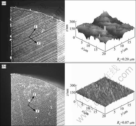
Fig.1 CCD images and AFM images of cutting tool before (a) and after (b) honing

Fig.2 Average surface roughness as function of honing time
Fig.4 shows the critical scratch load and optical microscope images as a function of average surface roughness value (Ra). For TiN and TiAlN coating layers, the critical scratch load decreased with increasing Ra value. This result was compatible with the trend found by another group[10], and the highest critical loads of 98 N (TiN coating) and 114 N (TiAlN coating) were obtained with Ra of 0.028 μm. In addition, it was found that the critical load was abruptly reduced when Ra changed from 0.028 to 0.055 μm, while the critical load decreased slightly with variation of Ra from 0.055 to 0.212 μm. Also, these micrographs were obtained at a point in scratch channel with a maximum load of approximately 114 N. No large cracks or chips were found on the side of scratch channel.
However, the width of the scratch channel increased with increasing surface roughness, indicating that the substrate was more plastically deformed due to the increase in surface roughness. Therefore, it is suggested that the adhesion between the coating and substrate was largely affected by both the surface morphology of the coating and the surface roughness of the substrate.
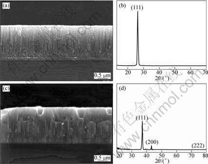
Fig.3 SEM micrographs and XRD patterns of TiN (a, b) and TiAlN (c, d) coatings deposited by AIP technique

Fig.4 Critical scratch load and optical microscope images as function of average surface roughness value
3.3 Cutting performance
In order to evaluate the cutting performance of end-mill tool under high-speed machining, six kinds of tools were evaluated. Fig.5 shows the comparisons of cutting performance of honing effect on uncoated sample, TiN and TiAlN coatings. All the tool wear increased as the cutting length increased, as shown in Fig.5(a). The value of tool wear by honing tool was smaller than that by no honing tool at a certain cutting length. This trend seemed due to higher critical load, that is better adhesion between coating layer and substrate, as shown in Fig.4. The tool life of the cutting tools is presented in Fig.5(b). As expected, the horned TiAlN coating tool showed the best cutting performance among the evaluated cutting tools under high-speed machining conditions. In the case of non-honing, the tool life of TiAlN coating tool increased by 35% compared with TiN coating tool. On the other hand, the tool life of TiAlN coating tool increased by 80% compared with TiN coating tool after honing. Overall, the performance of WC-Co tool without coatings was found to be very poor in high-speed cutting conditions.
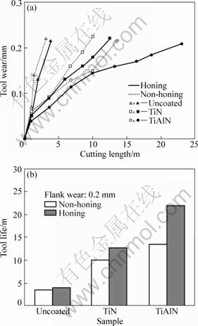
Fig.5 Comparisons of cutting performance with honing effect on uncoated, TiN and TiAlN coatings
4 Conclusions
1) TiN and TiAlN coatings were deposited onto substrates and cutting tool of WC-Co material by AIP method. The honing curves according to surface roughness showed a rapid improvement initially and thereafter became steady. The optimal honing time was determined to be approximately 20 s.
2) For TiN and TiAlN, the highest critical loads of 98 and 114 N, respectively, were obtained at average surface roughness of 0.028 mm.
3) Adhesion between the coating and substrate was considerably affected by both the surface morphology of the coating and the surface roughness of substrate.
4) In the case of non-honing, the tool life of TiAlN coating tool increased by 35% compared with TiN coating tool, and the tool life of TiAlN coating tool increased by 80% compared with TiN coating tool after honing.
References
[1] Ke Y l, Dong H y, liu g, Zhang m. Use of nitrogen gas in high-speed milling of Ti-6Al-4V [j]. Transactions of Nonferrous Metals Society of China, 2009, 19(3): 530-534.
[2] Kang m C, Kim j s, Kim k h. Fractal dimension analysis of machined surface depending on coated tool wear [J]. Surface and Coatings Technology, 2005, 193(1-3): 259-265.
[3] LI Ming-sheng, FENG Chang-jie, WANG Fu-hui. Effect of partial pressure of reactive gas on chromium nitride and chromium oxide deposited by arc ion plating [J]. Transactions of Nonferrous Metals Society of China, 2006, 16(s1): s276-s279.
[4] D’Errico G E, Guglielmi E, Rutelli G. A study of coatings for end mills in high speed metal cutting [J]. Journal of Materials Processing Technology, 1999, 92-93: 251-256.
[5] Kwon D H, Kang M C, Kim J S, Ok J T, Kim K H. A comparative study on cutting performance of TiN-coated tungsten carbide cutting tool with a cobalt interlayer [J]. Surface and Coatings Technology, 2005, 200(5-6): 1933-1938.
[6] Parks r e, Evans c j. Rapid post-polishing of diamond-turned optics [j]. Precision Engineering, 1994, 16(3): 223-227.
[7] Yu a b, Xu y s, Chen s f, Lin b, Tian x l. Analysis of material removal in alumina ceramic honing [j]. Journal of Materials Processing Technology, 2002, 129(1-3): 167-170.
[8] Jones m i, McColl i r, Grant d m. Effect of substrate preparation and deposition conditions on the preferred orientation of TiN coatings deposited by RF reactive sputtering [j]. Surface and Coatings Technology, 2000, 132(2-3): 143-151.
[9] Pinkas m, Pelleg j, Dariel m p. Structural analysis of (Ti1-xAlx) N graded coatings deposited by reactive magnetron sputtering [J]. Thin Solid Films, 1999, 355-356: 380-384.
[10] Efeoglu I, Arnell R D. Multi-pass sub-critical load testing of titanium nitride coatings [J]. Thin Solid Films, 2000, 377-378: 346-353.
(Edited by FANG Jing-hua)
Foundation item: Project(2010-0008-277) supported by NCRC Program through the National Research Foundation of Korea funded by the Ministry of Education, Science and Technology; Project supported by Pusan National University Research Grant, Korea
Corresponding author: Myung-Chang KANG; Tel: +82-51-510-2361; E-mail: kangmc@pusan.ac.kr; Hyung-Woo LEE; Tel: +82-51-510-3160; E-mail: LHW2010@pusan.ac.kr

