J. Cent. South Univ. Technol. (2011) 18: 690-696
DOI: 10.1007/s11771-011-0749-8
Optimal design of auxiliary-teeth to solve circulation current reduction of permanent magnet linear synchronous motor
JANG Ki-bong, KIM Jee-hyun, AN Ho-jin, KIM Gyu-tak
School of Mechatronics, Changwon National University, Changwon 641-773, Korea
? Central South University Press and Springer-Verlag Berlin Heidelberg 2011
Abstract: A discontinuity of magnetic circuits according to the end effect is generated in the permanent magnet linear synchronous motor (PMLSM). Due to the unbalanced back electro-motive force (EMF) and impedance produced, unbalanced current is generated. The circulating current, which is caused by a decrease in the thrust, is generated by the unbalanced current. The optimal design of auxiliary-teeth at the end of the mover was carried out to solve the unbalance of phase by using design of experiment (DOE), and compared with the basic model through finite element analysis (FEA). As a result, the auxiliary-teeth model compensates for the decrease of thrust caused by the unbalanced phase. Also, this model is proven to reduce the detent force by the vibration and noise of the PMLSM and copper loss caused by the circulating current.
Key words: permanent magnet linear synchronous motor; auxiliary-teeth; circulation current; end effect; thrust reduction
1 Introduction
The permanent magnet linear synchronous motor (PMLSM) has high thrust density, and its high speed and precise position can be obtained [1-2]. So, the PMLSM has been widely used in industries such as manufacturing equipment of semiconductors and plasma display panel/ liquid crystal display (PDP/LCD) [3-7]. But, detent force exists in PMLSM. So, the auxiliary-tooth is applied to reduce the detent force [8]. The winding of the mover is selected in either series or parallel depending on the usable DC link voltage and the maximum speed of PMLSM. In the case that high thrust is needed, the parallel circuit is inevitable to maintain back electro- motive force (EMF) constant appropriately [9-10]. But, the unbalanced current that flows to the inside of a parallel circuit of each phase is produced by an unbalance of back-EMF and impedance, because the magnetic circuit becomes inevitably unbalanced due to the end effect of PMLSM. Such unbalanced current results in the circulating current, which in turn causes a decrease in the thrust [11-12]. So, the optimal design of auxiliary-teeth at the end of the mover is carried out to solve the unbalance of phase. The auxiliary-teeth model is designed by using design of experiment (DOE), and compared with the basic model through finite element analysis (FEA) [13-15]. Then, the effect of the unbalanced phase based on the auxiliary-teeth installation is considered.
2 Analysis model specification
In this work, the analysis model is a moving coil-type PMLSM with a pole-to-coil ratio of 4:3. And the moving coil concentrated windings have two parallel circuits.
The permanent magnet is skewed by one-third of the pole pitch to reduce the detent force according to the slot-teeth structure. The analysis model specification is given in Table 1.
The analysis model is applied with three phases- 220 V, whose parallel circuits are likely to reach a speed more than 3 m/s. The structure of the moving coil-type PMLSM and the connection diagram of coil are shown in Fig.1. The flux linkage, back-EMF and inductance in coil-U1 and coil-V2 located in both ends are lower than others due to the discontinuity of the magnetic circuit. The circulating current is generated in parallel circuits due to the unbalanced phase stated above. And a back-braking thrust comes from the circulating current, which, in turn, results in decreased thrust, vibration and noise.
3 Method of measurement and consideration of influence on unbalanced phase due to end effect
Figure 2 shows part of the measurement equipment. The stator of the PMLSM was fixed on the sliding bed. It was fixed on the linear motion guide in order to reduce the frictional force and to move freely. The thrust of the stator was measured by using the load cell, which was fixed to the sliding bed when the mover was moved according to the law of action and reaction.
Table 1 Specification of analysis model

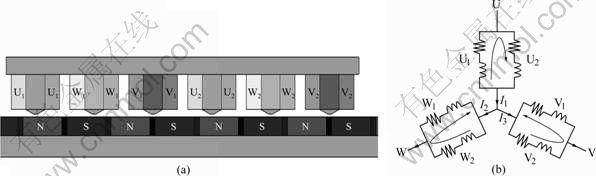
Fig.1 Structure of PMLSM: (a) Structure of moving coil; (b) Connection diagram
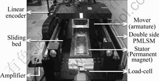
Fig.2 Prototype machine
3.1 Back-EMF
Back-EMF was measured by operating the double- sided PMLSM at a velocity of 1 m/s and then a voltage of each phase was measured by oscilloscope. Figure 3 shows the analyzed and measured results of back-EMF. The higher flux linkage is made in the W-phase than other phases because of the difference in magnetic resistance due to the end effect. In the result, the back-EMF of the W-phase located between the U and V phases is higher than that of other phases. The back-EMF constant is displayed in Table 2. As shown in Table 2, the maximum root-mean-square (RMS) value of the W-phase is 39.16 V×s/m, which is higher than that in other phases. Besides the back-EMF constants of the U and V phases are calculated to be lower than the W-phase by 1.96% and 3.06%, respectively. From the results of the experiment, the total unbalanced rate (Ru) of the back-EMF constant is 3.12%.

Fig.3 Back-EMF
Table 2 Back-EMF constant

3.2 Inductance and current
The value of inductance is calculated by the following equation:
 (1)
(1)
where I is the current; V is the voltage; Z is the impedance; R is the resistance; L is the inductance.
The analyzed and measured values of the inductance are presented in Table 3. Referring to the analyzed and experimental values, it is clear that the inductance values of U1 and V2 of the armature coils located at the end of the mover are the smallest due to the large magnetic resistance.
Table 3 Inductance

So, the unbalanced inductances of the U and V phases are generated, and the unbalanced rate (Ru) of inductances on each phase is 10.22%. The unbalance of back-EMF and inductance in each phase causes the inner circulating current flowing in each phase.
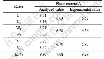
When the balanced three-phase voltage is supplied to PMLSM, both the FEA value and measured value of phase current are measured, as shown in Fig.4. The RMS values of FEA and the experimental and circulating currents are given in Table 4. As shown in Table 4, the current unbalance rate (Ru) of each phase is 9.29%, which is caused by the inner circulating currents flowing in each phase. This results in a thrust reduction. Besides, the poor control system performance caused by the back-braking power is the result of the circulating current.
3.3 Thrust
In the case of supplying direct current to the PMLSM, the L component does not appear and only the R component remains. This means that the thrust is generated in a balanced current condition. On the other hand, when the PMLSM is supplied with balanced three- phase AC voltage, in which the voltage of each phase is identically set as a way to distribute 6.53 A of current into the W-phase with variable resistance, the thrust is generated in an unbalanced current condition. Figure 5 shows the thrusts generated according to the load angle in both cases. By comparing the measured thrusts in both cases, the thrust change due to the inner circulating current can be confirmed, as shown in Table 5.

Fig.4 Current waveforms
Table 4 RMS value of phase-current
Because the thrust constant KT of the applied model is 111.76 N/A and the calculated circulating current Ic is 0.29 A using FEA, thrust reduction is predicted to be about 10.80 N. This is caused by the circulating current in the unbalanced state, in comparison with the balanced state. Actually, thrust reduction is confirmed as 22.45 N using FEA compared with the results of both cases.

Fig.5 Change of thrust in balanced and unbalanced state
Table 5 Comparison of balanced thrust and unbalanced thrust

It is also clear that the unbalanced phase state generated as a result of the discontinuous magnetic circuit causes the thrust reduction because the decrement of thrust in the unbalanced state is 31.54 N; therefore, the thrust is reduced by 4.36% compared with the balanced state. The reason why the measured value of thrust in a balanced current state does not show the perfect sinusoidal wave is positioning tolerance of the mover and detent force.
4 Optimal design of auxiliary-teeth
As discussed earlier, in the case of the PMLSM with a parallel circuit, the generated thrust decreases because of the unbalanced phase due to the end effect, which results in the inner circulating current. To eliminate the unbalanced phase caused by the end effect, the optimal design of auxiliary teeth is carried out, as shown in Fig.6.

Fig.6 Optimal design of auxiliary-teeth
FEA and DOE were used for the optimal design of auxiliary-teeth [10-11]. Figure 7 shows the inductance change according to the design parameters. The distance d from the center of the mover-teeth, the width w and the height h of the auxiliary-teeth are 34.5, 10 and 8 mm, respectively. As shown in Fig.7, the height has a decisive effect on the balanced inductance. Therefore, the optimal detail design of the auxiliary-teeth model is carried out by controlling the height of the auxiliary- teeth.
5 Influence of auxiliary-teeth installation
5.1 Back-EMF
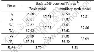
In the case of PMLSM with auxiliary teeth, an influence of a discontinuous magnetic circuit is obvious, which improves the discontinuity of flux linkage so that the improved unbalanced rate (Ru) of back-EMF is predicted. A comparison of the back-EMF constants of the basic model and auxiliary-teeth model are given in Table 6.
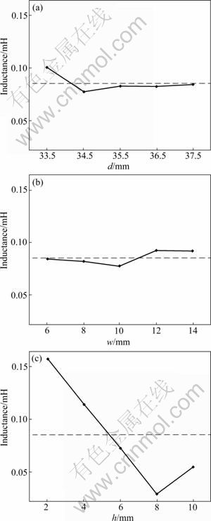
Fig.7 Inductance changes according to design parameters: (a) Distance from center of mover-teeth; (b) Width of auxiliary- teeth; (c) Height of auxiliary-teeth
It is clear that the generated unbalanced back-EMF constants of the U and V phases in the basic model are significantly improved after the installation of auxiliary teeth. The total unbalanced rate (Ru) of the back-EMF constant of the auxiliary-teeth model is improved to 3.53%, compared with that of the basic model, which is 5.70%.
Table 6 Comparison of back-EMF constants between basic model and auxiliary-teeth model
5.2 Inductance and current
A comparison of the inductances of the basic model and auxiliary-teeth model is given in Table 7.
Table 7 Comparison of inductance between basic model and auxiliary-teeth model

In case of the optimal auxiliary-teeth model, the unbalanced rate (Ru) of inductance is considerably improved to 0.40%, compared with that of the basic model and an unbalance between two coils connected in parallel has undergone improvement, too.
As stated above, the diminishments of unbalanced back-EMF and inductance result in the reduction of unbalanced current flowing in each coil by using Eq.(1).
Figure 8 shows the currents flowing in each coil of the basic model and auxiliary-teeth model, and their RMS values are given in Table 8. As shown in Table 8, in case of the optimal auxiliary-teeth model, the unbalanced rate (Ru) of current is improved to 5.51%, compared with that of the basic model, 9.97%, so that the total inner circulating current is significantly decreased to 0.155 A. It is expected to compensate for the decreased thrust due to the decrease of circulating current in the auxiliary- teeth model.

Fig.8 Current waveforms of each coil: (a) Basic model; (b) Auxiliary-teeth model
Table 8 Comparison of RMS values of phase current

5.3 Thrust
Generated thrusts of the basic model and the auxiliary-teeth model are compared to confirm the effect of the circulating current due to the unbalanced phase of the thrusts. The generated thrust for the basic model in the balanced current state and the generated thrusts for the basic model and the auxiliary-teeth model in the unbalanced current state are shown in Fig.9. Also the thrust constant (Kt) and circulating current (Ic) are compared in Table 9.
It can be seen that the decrement of thrust for the auxiliary-teeth model is about 5.88 N, which is lower than that of the basic model, so it is predicted that the total generated thrust of the auxiliary-teeth model is higher than that of the basic model in theory.
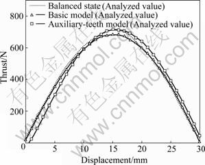
Fig.9 Comparison of generated thrusts in balanced and unbalanced current state
Table 9 Comparison of thrust constants

Also, it is confirmed that the total analytical generated thrust of the auxiliary-teeth model is increased to 719.1 N, while it is 703.4 N in the case of the basic model. Therefore, it is clear that the auxiliary-teeth model compensates for the decrease of thrust caused by the unbalanced phase. However, there is a difference between the theoretical value and the analytical value. So, it seems that there are other reasons that decrease the thrust, except for the circulating current.
5.4 Detent force
A traditional auxiliary-teeth method has been applicable to reduce the detent force, so a variation of the detent force of the optimally designed auxiliary-teeth model is considered.
Figure 10 shows the detent forces of the basic model, which is supplied with overhang and skewing of the permanent magnet and the auxiliary-teeth model. As shown in Fig.10, by applying the auxiliary-teeth case, the detent force decreases by 64.3% compared with the basic model.
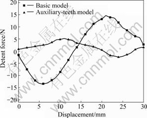
Fig.10 Comparison of detent force between basic model and auxiliary-teeth model
6 Conclusions
1) The validity of applying implementing auxiliary- teeth is verified through the comparison of the performances in the basic model and the auxiliary-teeth model. As a result, the auxiliary-teeth model compensates for the decrease of thrust caused by the unbalanced phase.
2) The auxiliary-teeth model has proven to decrease the detent force responsible for the vibration and noise of the PMLSM as well as copper loss caused by the circulating current.
References
[1] LEE Dong-Yeup, KIM Gyu-Tak, CHOI Jung-Keying. The design for high power density in the slotless type permanent magnet linear synchronous motor [C]// INTERMAG. Nagoya, Japan, 2005: 653- 654.
[2] RADWAN T S, RAHMAN M A, OSHEIBA A M, LASHINE A E. Dynamic analysis of a high performance permanent magnet synchronous motor drive [C]// Electrical and Computer Engineering, (Canadian Conference on Vol.2). Calgary, Canada, 1996: 611-614.
[3] SANADA M, MORIMOTO S, TAKEDA Y. Interior permanent magnet linear synchronous motor for high performance drives [J]. IEEE Trans Industry Application, 1997, 33(4): 966-972.
[4] CHUNG Shi-Uk, KANG Do-Hyun, CHANG Jung-Hwan, KIM Ji-Won, LEE Ji-Young. New configuration of flux reversal linear synchronous motor [C]// International Conference on Electrical Machines and System. Seoul, Korea, 2007: 864-867.
[5] KARITA M. Present status of linear drives for industry applications in Japan [C]// Proc of LDIA01. Nagano, Japan, 2001: 462-467.
[6] ZHU Yu-wu, LEE Sang-Gun, CHUNG Koon-Seok, CHO Yun-Hyun. Investigation of auxiliary poles design criteria on reduction of end effect of detent force for PMLSM [J]. IEEE Trans Magnetics, 2009, 45(6): 2863-2866.
[7] CHUNG Shi-UK, LEE Hong-Joo, HWANG Sang-Moon. A novel design of linear synchronous motor using FRM topology [J]. IEEE Trans on Magnetics, 2008, 44(6): 1514-1517.
[8] BATAR Nyambayar, HEE Sung-Yoon, MINH Trien-Pham, SHIN Pan-Seok, KOH Chang-Seop. Shape optimal design of a 9-pole 10-slot PMLSM for detent force reduction using adaptive response surface method [J]. IEEE Trans Magnetics, 2009, 45(10): 4562-4565.
[9] YOSHIDA K, LEE J, KIM Y J. 3-D FEM field analysis in controlled PMLSM for maglev vehicle [J]. IEEE Trans Magnetics, 1997, 33(2): 2207-2210.
[10] EDIHARA D, KIM H J, KAWAMOTOR Y, TORII S, WATADA M. Study of the transport system with PM type LSM [C]// Annual Conference of IEEE Industry Applications Society. Toronto, Canada, 1993: 53-56.
[11] LIM Ki-chae, WOO Joon-Keun, KANG Gyu-Hong, KIM Gyu-Tak. Detent force minimization techniques in permanent magnet linear synchronous [J]. IEEE Trans Magnetics, 2002, 38(2): 1157-1160.
[12] JULIEN Gomand, GHISLAIN Remy, ABDELMOUNAIM Tounzi, BARRE Pierre-Jean, HAUTIER Jean-Paul. Impact of permanent magnet field on inductance variation of a PMLSM [J]. IEEE Trans Power Electronics and Application, 2007, 10: 1-9.
[13] KIM Sung-Il, LEE Ji-Young, KIM Young-Kyoun, HONG Jung-Pyo. Optimization for reduction of torque ripple in interior permanent magnet motor by using the Taguchi method [J]. IEEE Trans Magnetics, 2005, 41(5): 1796-1799.
[14] OMEKANDA A M. Robust torque and torque-per-inertia optimization of a switched reluctance motor using the Taguchi methods [J]. Industry Applications, IEEE Trans, 2006, 42(2): 473- 478.
[15] YOUN S, LEE J, YOON H, KOH C. A new cogging-free permanent-magnet linear motor [J]. IEEE Trans Magnetics, 2008, 44(7): 1785-1790.
(Edited by YANG Bing)
Foundation item: Work supported by the Second Stage of Brain Korea 21 Projects and Changwon National University in 2009-2010
Received date: 2010-03-28; Accepted date: 2010-06-24
Corresponding author: KIM Gyu-tak, PhD, Professor; Tel: +82-55-213-3635; E-mail: gtkim@changwon.ac.kr

