J. Cent. South Univ. Technol. (2011) 18: 458-464
DOI: 10.1007/s11771-011-0718-2
Optimal design of FRMSM to decrease detent force
JANG Ki-Bong, PYO Se-Ho, AN Ho-Jin, KIM Gyu-Tak
School of Mechatronics, Changwon National University, Changwon 641-773, Korea
? Central South University Press and Springer-Verlag Berlin Heidelberg 2011
Abstract: An optimal configuration of the flux-reversal linear synchronous motor (FRLSM) with the optimal number of attachment permanent magnets (PMs) was presented. The optimal model of 2 000 N was designed to reduce the detent force by redesigning the air-gap structure and skewing. The design parameters, mover PMs and stator core, were selected for optimal design by DOE. The thrust and the detent force of the designed optimal models were compared by finite element analysis (FEA). As a result, the thrust of the optimal model is slightly decreased by 1.97% compared with the basic model, and the detent force of the optimal model is greatly decreased by 88.47% compared with the basic model.
Key words: flux-reversal linear synchronous motor; detent force; thrust; design of experiment; skew and overhang
1 Introduction
Permanent magnet linear synchronous motor (PMLSM) has the advantages of high thrust, low maintenance costs, high speed, and precision position control, and it does not need any mechanical mechanism for making linear thrust [1-3]. So, it is used widely on industrial sites, such as in manufacturing equipment [4-5].
But, when PMLSM is used in the middle and long-distance linear gantry robot system, the number of permanent magnets (PMs) is increased, leading to a significant increase in cost [6-8]. Besides, the magnetic flux of PMs can have a negative effect on the other parts except for the motor or can be damaged by the attachment of the magnetic material [9-10].
In order to improve this limitation of PMLSM, the mover of the flux-reversal linear synchronous motor (FRLSM), with the magnet and armature aligned together, is suggested. Also, the stator is composed of only the iron core [11].
The existing FRLSM has a structure that inserts two PMs and has the same polarity [12-14]. But in this study, different numbers of attachment PMs are inserted into armature teeth of the FRLSM.
The quality of the FRLSM in which the multiple PMs were inserted into the mover is compared and analyzed. Then, the optimal PMs insertion number, the ratio of stator slot to teeth, and the number of projecting parts per whole length of the mover are selected. In addition, the optimal model is designed to reduce detent force by redesign of the air-gap structure and skewing [15].
2 Design of FRMSM
2.1 Precedence model
Fig.1(a) shows the structure and flux line of the existing FRLSM, and Fig.1(b) shows the structure and flux line of the proposed FRLSM in precedence gradation. The primary model has two adjacent PMs in lower armature teeth, and each PM has a different polarity. This configuration of the primary model has a lower thrust density than the PMLSM. In order to reduce the weakness, lower armature teeth are divided into three parts, and the PMs, which have the same polarity, were inserted in both ends. Also, the core is inserted between both PMs, so the magnetic air-gap is reduced. This structure can make up for the weak point, which has a flux linkage remarkably lower than PMLSM because the magnetic air-gap is increased by PMs of lower armature teeth in existing FRLSM. The back electromotive force (EMF) and thrust are raised by about 200% due to the increase of the flux linkage compared with the existing FRLSM. However, the optimal design must reduce the detent force, because the PMs and core, which have huge reluctance distinction from each other in lower armature teeth, were inserted.
2.2 Basic model selection
Fig.2 shows the structure of the FRLSM, according to the changing numbers of PMs (np) per armature tooth. The mover winding of the FRLSM consists of three phases, and each phase has two series winding. Also, the maximum thrust is produced when the ratio of stator slot to tooth is 1:2, as determined by finite element analysis (FEA), because the flux linkage exists largely at that time. Also, the volume of PM is selected as the same condition, and then the characteristic is compared by using FEA. In the cases of np=3, 4, and 5, the number of stator slots (22, 28, and 34) is increased according to the PMs and phase. It is optimal numbers with which the flux linkage does not offset in armature and stator.
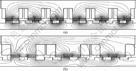
Fig.1 FRMSM structure of precedence study: (a) Primary model; (b) Proposed model
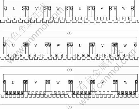
Fig.2 Structures of FRMSM according to np (with same polarity): (a) np=3; (b) np=4; (c) np=5;
Fig.3(a) shows the analyzed thrust according to np. In the cases of 3, 4, and 5 attachment PMs, the peak values of the fundamental harmonic of pullout thrust generate 2 344.94, 2 718.3 and 3 098.58 N (These values indicate the magnitude of fundamental harmonic), respectively. The increase in thrust is confirmed by the results of the analysis. Fig.3(b) shows the analyzed detent force according to np. In the cases of 3, 4, and 5 attachment PMs, the detent forces are highly increased to 419.53, 574.40, and 708.02 N, respectively. Fig.3(c) shows the harmonic order of thrust. The effect of the 2nd harmonic is very apparent by the end effect. It can be decreased by auxiliary teeth or auxiliary core equipment [8]. Meanwhile, the effects of the 5th harmonic due to the parallel effect of magnetization of the PM and the 6th harmonic due to the teeth-slot structure are highly generated. If PM is increased in number, the total harmonic distortion (THD) increases too. In the cases of 3, 4, and 5 attachment PMs, the THDs of thrust increase by 22.08%, 25.81%, and 26.99%, respectively. In this result, the harmonic order of thrust is increased by an additional PM.
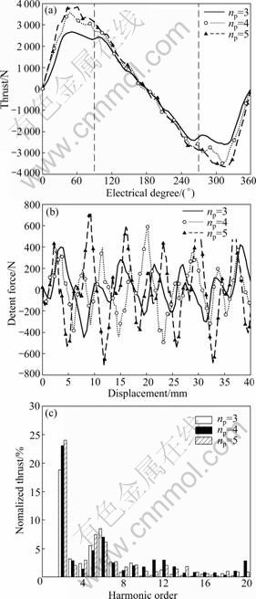
Fig.3 Characteristics according to input magnet: (a) Thrust; (b) Detent force; (c) Harmonic order
The detent force causes a noise, a vibration, and a fall of precision control, so it must be reduced. The detent force can be decreased by optimal design of the PM as well as stator core and by carrying out skew-overhang in this work. Also, the number of stator slots per general mover length is increased, so pole pitch is diminished. In the case of driving at 4 m/s, the operating frequencies are increased to 114.9, 153.25, and 191.38 Hz. As a result, core loss is highly increased. The thrust is increased by additional np. But, the overall performance is reduced due to a ripple of the thrust, which corresponds to the increase of the detent force, THD and core loss. And, the increment of the detent force is larger than that of the thrust. In these results, np is chosen as 3, and Fig.2(a) is selected as the basic model in this work.
2.3 Optimization
2.3.1 Optimal design of air-gap shape
The detent force of the basic model, whose np is 3, was 419.53 N. In order to decrease the 5th and 6th harmonics, the air-gap flux should be sinusoidal. The chamfer is applied in the lower part of the PM and upper part of the stator slot. The size is selected as a design parameter.
Fig.4 and Table 1 show the six design parameters. The inserted shape of the core between both PMs is not selected as a design parameter. Because of the flux leakage, which is, according to changing size, increased, it causes a large thrust decrease. The two stairs, which are the height and width of the chamfer in the lower part of the PM, are more efficient than one stair or three stairs, as determined by FEA. So, the height (HM1, HM2) and width (wM1, wM2) of the chamfer are designed to be divided into two parts. On one side, in the case that the chamfer height of stator slot HT is over 1 mm, the detent force is barely decreased. In the case of the height being less than 1 mm, manufacture is complicated when the height (HT) and width (wT) of chamfer in the stator slot are divided into two stairs. So, HT and wT are chosen for the one stair in the design parameter. The minimum detent force is selected by FEA according to the changing design parameter. Fig.5 shows the characteristics of the detent force according to the changing design parameters by orthogonal array using FEA. Table 2 gives the variables that make the minimum detent force among the design parameters. These parameters are selected to be the optimal model of the air-gap shape.
The detent force of the optimally designed model, which is applied to the design parameters by design of experiment (DOE), is 130.30 N, as shown in Fig.6(a). It is 68.94% less than the maximum value of the basic model, 419.53 N [9-10]. Because the flux of the air-gap is sinusoidal in shape changing of lower part of PM and upper part of stator teeth, it reduces the reluctance distinction of the air-gap. Fig.6(b) shows that the thrust characteristic has a sinusoidal distribution because the harmonic order of the optimally designed model is decreased due to the decline of the detent force. The maximum fundamental harmonic of thrust of the optimally designed model is 2 130.32 N. It is 9.15% less than the basic model. But, the thrust characteristic is improved due to a decrease in the 6th harmonic because the detent force, which is caused by tooth-slot structure, is decreased. From the result of harmonic order analysis, the THD of the basic model is 22.08%, and the THD of the optimal model is 17.23%. The harmonic order is decreased.
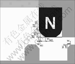
Fig.4 Design parameters
Table 1 Design parameters and variable range
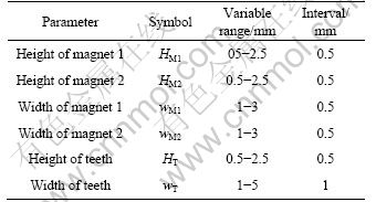
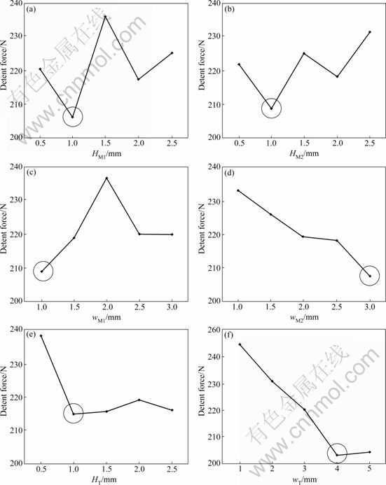
Fig.5 Detent forces according to design parameters: (a) HM1; (b) HM2; (c) wM1; (d) wM2; (e) HT; (f) wT
Table 2 Optimal parameters
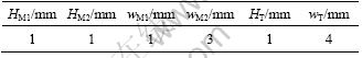
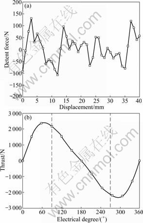
Fig.6 Characteristic of optimal model: (a) Detent force; (b) Thrust
2.3.2 Skew-overhang model
The detent force of 6th harmonic order is decreased due to the optimal shape of the air-gap. But, the 2nd and 5th harmonic orders still exist, so they have caused an overall fall in performance. In order to minimize the detent force, which includes the 2nd and 5th harmonic orders, skew-overhang is applied. In the case of applying skew, the 5th harmonic order by parallel magnetization and the 6th harmonic order by tooth-slot structure can be decreased.
So, THD can be reduced and the vibration and noise are decreased. On the other hand, there is a disadvantage such as decreased thrust. In order to compensate for the decreased thrust, overhang is applied in the PM. Finally, the skew-overhang model, which has the minimum detent force and less thrust than the basic model according to the skew length of the PM and overhang length, is designed. Fig.7 shows the detent force and the thrust of the optimal model according to the skew length in the mover core. In the case of FRLSM, the skew is applied in the mover, which is shorter than the stator, because the stator skewing is more expensive than the mover skewing. With increasing the skew length, the detent force is decreased, but it is not more than one-third of pole pitch.

Fig.7 Changes of thrust and detent force with skew length
The reducing effect of detent force is decreased when the pole pitch is 17.4 mm and the length of skew is more than 6 mm. If the skew length is increased, the maximum thrust should be decreased steadily. So, the skew length of the optimal model is selected as 6 mm. In the case of a skew length of 6 mm, the detent force is decreased from 130.30 to 35.75 N, and the maximum thrust is decreased from 2 426.0 to 2314.7 N. In order to compensate for decreased thrust due to skew, the overhang is increased to the axial direction length in the mover. If overhang is applied, the thrust can be increased by producing more flux linkage in the core. Fig.8 shows the changing of thrust according to overhang length of the mover core.
The thrust is increased by overhang when the skew of 6 mm is applied in PM. The maximum thrust of the optimal model, which is not applied to skew and overhang, is 2 426.0 N; the maximum thrust of the skew-overhang model that is applied to a skew of 6 mm and overhang of 3 mm is 2 418.0 N. As a result of the comparison, the maximum thrust is almost identical.
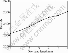
Fig.8 Change of thrust with overhang length
But, the fundamental harmonic of the maximum thrust of the optimal model generates 2 130.32 N, and that of the skew-overhang model generates 2 298.65 N. The detent force applied to the skew is 35.75 N and that applied to the skew-overhang is 47.04 N. As a result of the comparison, although the detent force is increased, the thrust is increased. So, this result can be satisfied.
Fig.9 and Table 3 show the comparison of the detent force, thrust and the harmonic order analysis of the basic model FRLSM, air-gap-shape optimal model FRLSM and skew-overhang model FRLSM, which is applied to a skew of 6 mm and overhang of 3 mm. The maximum detent force of the skew-overhang model is 47.04 N, which is 88.47% less than the basic model by redesign of the air-gap shape and skew-overhang. The fundamental harmonic of the maximum thrust of the skew-overhang model is 2 298.65 N, which is 1.97% less than the fundamental harmonic of the maximum thrust of 2 344.94 N of the basic model. The decrease in thrust is much less than the decrease in the detent force. Also, with respect to harmonic order analysis, as shown in Fig.9(c), the harmonics are the 5th harmonic order and 6th harmonic order, except the 2nd harmonic order, and are decreased by optimal design of the air-gap shape and skewing. The major component, which is the 2nd harmonic order of FRLSM, is decreased due to the optimal design of the air-gap shape without the auxiliary core and auxiliary teeth because the optimal design of the air-gap shape produces sinusoidal air-gap flux.

Fig.9 Characteristic of three 3 models: (a) Detent force; (b) Thrust; (c) Harmonic order
Table 3 Comparison of characteristics with three models
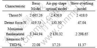
The 2nd harmonic order of the optimal model, which is the skew-overhang model, is decreased by 50.8% compared with the basic model. So, the THD of the basic model is 22.08%, and the THD of the skew-overhang model is 11.37% due to a decrease of the detent force. Therefore, the sinusoidal thrust can be generated more than the basic model.
3 Conclusions
1) The optimal design of the FRLSM shape is carried out to reduce the detent force and increase the thrust. The design parameters of mover PMs and stator core are selected for optimal design by DOE.
2) The skew is applied in order to decrease the detent force in the mover core, and the overhang is applied to compensate for the decrease of thrust in the mover.
3) The thrust and the detent force of the designed optimal models are compared by FEA. The result of the comparison is that the thrust of the optimal model is slightly decreased by 1.97% compared with the basic model, but the detent force of the optimal model is greatly decreased by 88.47% compared with the basic model.
References
[1] SANDA M, MORIMOTO S, TAKEDA Y. Interior permanent magnet linear synchronous motor for high performance drives [J]. IEEE Trans Industry Application, 1997, 33(4): 966-972.
[2] YOUN S, LEE J, YOON H, KOH C. A new cogging-free permanent-magnet linear motor [J]. IEEE Trans Magnetics, 2008, 44(7): 1785-1790.
[3] RADWAN T S, RAHMAN M A, OSHEIBA A M, LASHINE A E. Dynamic analysis of a high performance permanent magnet synchronous motor drive [C]// Canadian Conference on Electrical and Computer Engineering. Calgary, 1996: 611-614.
[4] EBIHARA D, KIM H J, KAWAMOTO Y, TORII S, WATADA M. Study of the transport system with PM type LSM [C]// Annual Conference of IEEE Industry Applications Society. Toronto: 1993: 53-56.
[5] YOSHIDA K, LEE J, KIM Y J. 3-D FEM field analysis in controlled PMLSM for maglev vehicle [J]. IEEE Trans Magnetics, 1997, 33(2): 2207-2210.
[6] HENDERSHOT J R Jr, MILLER T J E. Design of brushless permanent-magnet motor [M]. Oxford: Magna Physics Publishing and Clarendon Press, 1994: 1-26.
[7] KIM Sung-Il, LEE Ji-Young, KIM Young-Kyoun, HONG Jung-Pyo. Optimization for reduction of torque ripple in interior permanent magnet motor by using the Taguchi method [J]. IEEE Trans Magnetics, 2005, 41(5): 1796-1799.
[8] OMEKANDA A M. Robust torque and torque-per-inertia optimization of a switched reluctance motor using the Taguchi methods [J]. IEEE Trans Industry Applications, 2006, 42(2): 473- 478.
[9] LEE Dong-Yeup, KIM Gyu-Tak, CHOI Jung-Keying. The design for high power density in the slotless type permanent magnet linear synchronous motor [C]// INTERMAG 2. Japan: Nagoya Congress Center, 2005: 653-654.
[10] BATAR Nyambayar, HEE Sung-Yoon, MINH Trien-Pham, SHIN Pan-Seok, KOH Chang-Seop. Shape optimal design of a 9-pole 10-slot PMLSM for detent force reduction using adaptive response surface method [J]. IEEE Trans Magnetics, 2009, 45(10): 4562-4565.
[11] CHUNG Shi-Uk, LEE Hong-Joo, HWANG Sang-Moon. A novel design of linear synchronous motor using FRM topology [J]. IEEE Trans Magnetics, 2008, 44(6): 1514-1517.
[12] JULIEN G, GHISLAIN R, ABDELMOUNAIM T, BARRE P J, HAUTIER J P. Impact of permanent magnet field on inductance variation of a PMLSM [J]. IEEE Trans Power Electronics and Application, 2007, 10: 1-9.
[13] CHUNG Shi-Uk, KANG Do-Hyun, CHANG Jung-Hwan, KIM Ji-Won, LEE Ji-Young. New configuration of flux reversal linear synchronous motor [C]// International Conference on Electrical Machines and System. Seoul, Korea, 2007: 864 �C 867.
[14] SANADA S M, MORMOTO S, TAKEDA Y. Performance analysis of permanent magnet linear synchronous motors for wide constant power operation [J]. Electro Motion, 1996, 3(1): 13-16.
[15] LIM Ki-Chae, WOO Joon-Keun, KANG Gyu-Hong, HONG Jung-Pyo, KIM Gyu-Tak. Detent force minimization techniques in permanent magnet linear synchronous motor [J]. IEEE Trans Magnetics, 2002, 38(2): 1157-1160.
(Edited by YANG Bing)
Foundation item: Work supported by the Second Stage of Brain Korea 21 Projects
Received date: 2010-03-28; Accepted date: 2010-06-24
Corresponding author: KIM Gyu-Tak, PhD, Professor; Tel: +82-55-213-3635; E-mail: gtkim@changwon.ac.kr

