J. Cent. South Univ. (2016) 23: 1115-1122
DOI: 10.1007/s11771-016-0361-z

Side force formation mechanism and change law of TBM center cutter
XIA Yi-min(夏毅敏)1, 2, TIAN Yan-chao(田彦朝)1, 2, TAN Qing(谭青)1, 2, HOU Yu-meng(侯禹蒙)2
1. State Key Laboratory of High Performance Complex Manufacturing, Central South University,Changsha 410083, China;
2. School of Mechanical and Electrical Engineering, Central South University, Changsha 410083, China
 Central South University Press and Springer-Verlag Berlin Heidelberg 2016
Abstract: The center cutter of a hard rock tunnel boring machine (TBM) is installed on the cutterhead at a small radius and thus bears complex side force. Given this fact, the formation mechanism and change law of the side force suffered by the center cutter were studied. Based on the rock shear failure criterion in combination with the lateral rolling width, a model for predicting the average side force was set up. Besides, a numerical analysis model of the rock fragmentation of the center cutter was established, and the instantaneous load changing features were investigated. Results shows that the inner side of the center cutter can form lateral rolling annulus in rock during the rotary cutting process. The smaller the installation radius is, the greater the cutter side force will be. In a working condition, the side force of the innermost center cutter is 11.66 kN, while it decreases sharply when installation radius increases. Variation tends to be gentle when installation radius is larger than 500 mm, and the side force of the outermost center cutter is reduced to 0.74 kN.
Key words: tunnel boring machine; center cutter; rotary cutting; installation radius; side force
1 Introduction
The hard rock tunnel boring machine (TBM) is widely used in tunnel engineering and it mainly relies on the movement of disc cutters driven by the cutterhead to roll forward [1-2]. According to the installation position, disc cutters can be divided into center cutters, front cutters and edge cutters. As the center cutter has a small installation radius, its loading condition is relatively complex. Especially when its side forces is large, a series of failure problems for the center cutter will arise, which can significantly impact the service life of the cutter.
Cutter load and rock fragmentation mechanism are closely related. Many scholars [3-5] have studied the interaction mechanism of disc cutters and rock, pointing out that the rock fragmentation is a result of the comprehensive action of extrusion failure, shear failure and tensile failure. Based on the study of the evolution law of rock cracks and the crushing mechanism, a large number of scholars have conducted research on the influencing factors of the cutter load and the load prediction model. BALCI and TUMAC [6] carried out research on the influence of different rock constitution on the cutter load. JI et al [7] studied the influence of the disc cutter spacing on the jump break coefficients via indentation experiments with different cutter spaces. GERTSCH et al [8] investigated the effect of TBM working parameters on the cutter load based on linear cutting. MOON and OH [9] simulated the cutting process under conditions of different cutter penetrations and spaces through discrete element software, and then verified the simulation with a linear cutting experiment platform. ROSTAMI [10-11] analyzed the stress distribution of the rock crushed zone beneath the disc cutter, and obtained the prediction model for normal force and rolling force based on the linear cutting experimental data. Besides the linear cutting research above, XIA et al [12-13] studied the influencing factors of the cutter load and analyzed the rotary cutting load model, which was verified through a rotary cutting experiment platform. HUO et al [14] analyzed the mechanical parameters of the disc cutter with different modes. The aforementioned research is mainly focused on the front disc cutter, but the load characteristics of the center cutter differ considerably with those of the front disc cutter since the center cutter has a small installation radius and bears large irregular side force in particular. The side force and the torque caused by the force may lead to the destruction of the disc cutter ring and bearings,which can further result in serious failure for the disc cutter [15].
In this work, the motion characteristics of the center cutter are first studied. Then on this basis, the generating mechanism of the side force of the center cutter is investigated, and the computing model of the mean side force is built. Subsequently, the instantaneous value of the side force of the cutter is analyzed based on finite element numerical simulation, and the change law of the side force of the cutter is explored. Besides, the disc cutter rotary cutting experiment platform is used to verify the prediction model of the side force of the center cutter.
2 Side force formation mechanism of center cutter
2.1 Rotary cutting characteristics of center cutter
When the TBM cutterhead moves forward, the disc cutter rotates around the axis of the cutter head and around its own axis simultaneously. The cutter penetrates into the rock with a certain length and breaks the rock in the contact area, which includes arc segment AD and area ABD on both sides of the cutter ring, but the rear half of the cutter, represented as area BCD, is not involved in rock fragmentation, as shown in Fig. 1(a).

Fig. 1 Diagrams showing trajectory of cutter rotation on tunnel face:
The projection of the cutter on the tunnel face can be simplified to a line AC as shown in Fig. 1(b). AC rotates around the center point O of the cutterhead on the tunnel face at a fixed angular velocity. Section AB slips inward and section BC slips outward when the disc cutter moves from position 1 to position 2. The front half, represented as area AB, is involved in rock fragmentation while the rear half, represented as area BC, is not in contact with the rock during the rotation process. The sliding trajectory of section AB forms an annulus groove on the tunnel face.
As shown in Fig. 1(b), in the motion process, the cutter forms an annulus, the width of which is larger than that of the cutter. The annulus width w caused by lateral rolling is the difference between OA and OB, and is denoted as AE in Fig. 1(b). OB equals the installation radius R and OA can be calculated through AB and OB. Then the annulus width w can be calculated as follows:
 (1)
(1)
where R is the installation radius and r is radius of the cutter and h is the penetration.
When the installation radius of the cutter is small, the annulus width w can be quite large. For the penetration h=6 mm and the installation radius of the cutter 76 mm, the annulus width can reach 15.28 mm. Nevertheless, with the increase of the installation radius of the cutter, the annulus width decreases drastically. After reaching a certain degree, the annulus width varies slowly with the installation radius, as shown in Fig. 2(a). The trajectories of the cutters with different installation radii are a set of concentric annuli, and the annulus width is getting larger as the cutter is getting closer to the center of the cutterhead. The rolling trajectory of the common 17-inch disc cutter is shown in Fig. 2(b).
2.2 Formation mechanism of side force
In the process of rock fragmentation, the two sides of the cutter bear the rock reaction forces F1 and F2, respectively. The side force of the cutter Fs, which is caused by the imbalance between the two forces F1 and F2, equals the difference of F1 and F2. According to the motion analysis above, when the cutter conducts rotary motion, area ABD exerts a lateral rolling action on the inside rock. For the center cutter, the lateral rolling action is especially evident due to its relatively small installation radius. The rotary cutting motion of the center cutter leads to the difference between F1 and F2, and thus the side force of the cutter arises. As the installation radius of the cutter gets smaller, the lateral rolling action exerted by the inside of the cutter on the rock is more evident, the difference between the inside load and the outside load of the cutter becomes larger, and, accordingly, the side force gets larger. However,when the installation radius of the cutter is large, the rotary cutting action of the cutter is not evident and there is no distinct difference between the loads of the two sides, which is similar to the linear cutting process. In this process, the disc cutter assumes an instantaneous side force due to randomness and non-uniformity of rock fragmentation. Yet in idealized conditions, the force exerted on both sides of the cutter is more or less the same in the linear cutting process, and the mean side force is supposed to approach zero.

Fig. 2 Variation of annulus width with installation radius:
In the rotary cutting process of the center cutter, the rolling action on the inside rock leads the force of the inside cutter to be larger than that of the outside part. Therefore, the side force on the cutter points to the outside of the cutterhead. The lateral rolling annulus is the motion trajectory of the cutter, which is a concept different from the large rock chunks flaked off by the cutter. However, the lateral rolling annulus groove formed by the rotary motion of the cutter has impact on the inside rock stress, leading to relatively evident crushing effects of the inside rock.
2.3 Prediction model of mean side force based on shear failure
The lateral rolling on the inside rock results in the imbalance between the forces of the two sides of the cutter, hence the side force. The area of the rolling annulus groove exerts a direct influence on the magnitude of the side force. As can be seen in Fig. 1, after completing a process of rock fragmentation, the cutter rotates from position 1 to position 2, rotating through an angle α on the tunnel face, as shown in Fig. 1(b). For a pure rolling of the disc cutter, there exists:
 (2)
(2)
where φ is the contact angle between rock and cutter,and it can be calculated by:
 (3)
(3)
 (4)
(4)
When the cutter rotates an angle α on the tunnel face, the inner side of the cutter can chip off rocks with area S, and it can be calculated by:
 (5)
(5)
Rock near the cutter mainly breaks in shear failure due to mechanism of rock failure. Thus the side force can be calculated by:
 (6)
(6)
where στ is the shear strength of rock.
Based on Eq. (6), the respective side forces of each cutter in a penetration of 4 mm, 6 mm, 8 mm and 10 mm and a rock shear strength of 12 MPa are calculated, and the curve that the side force varies with the installation radius is shown in Fig. 3(a). The side force of the cutter is large when the installation radius is small. It first decreases rapidly with the increase of the installation radius, and then decreases gentlely with small values. Moreover, for the cutters installed at the same position, the deeper the penetration is, the larger the side force of the cutter becomes. The lateral rolling annulus widths, corresponding to the penetration 6 mm and 8 mm with the cutter at different positions are calculated respectively. The curve of the side force changing with the annulus width is shown in Fig. 3(b), where the side force of the cutter increases as the annulus width increases. When the annulus width is small, the side force is also small. In this case, the penetration has little effect on the side force. With the increase of the annulus width, the side force of the cutter increases almostlinearly in each penetration. When the annulus width remains the same, the side force of the cutter in a larger penetration is larger and the difference is getting larger with the increase of the annulus width.

Fig. 3 Variation of theoretical side force with cutter installation radius and lateral annulus width:
3 Change law of instantaneous side force of center cutter
In order to study the instantaneous change law of the side force of the center cutter, a numerical analysis model of the center cutter is built with FEM Analysis Software, and simulation analysis on the interactions between the center cutter and the rock is conducted.
3.1 Simulation modeling of center cutter
The 17-inch disc cutter commonly used in engineering is selected, with a cutter angle of 10° and a cutter width of 20 mm. To simplify the cutter model, only a model of the cutter ring is built with rigid constraints. TBM center cutters in a given project are chosen, and their installation radii are shown in Table 1. A hinge relation is established between the cutter centerand the rotary center of the cutterhead, so that the disc cutter can rotate around its own axis due to friction at the same time when it rotates around the axis of the cutterhead.
Table 1 Installation radius of cutter

The extended Drucker-Prager model is adopted to set rock materials. In this model, the yield criterion and flow law of the rock are defined. For the shape of the yield surface on the plane of the meridian, a linear model is used. The yield criterion function is:
 (7)
(7)
 (8)
(8)
where t is the deviatoric stress parameter; r is the third invariants of the stress deviator; k is the ratio of the three-axis tensile yield stress to the three-axis compressive yield stress; d is the cohesive force of materials; β is the friction angle of materials; q is the Mises equivalent stress; P is the mean compressive stress.
The flow law is defined by the hardening law and the plastic flow potential. The essence of the hardening law is to control changes in the area of the yield surface through the relation between the equivalent stress  and the equivalent plastic strain
  The plastic potential surface function of the linear Drucker-Prager model is:
 (9)
(9)
where ψ is the dilation angle of materials.
As the rotary radius is small, the inside boundary has a considerable influence on the model. Therefore, a semi-cylinder shaped cell is selected to eliminate the influence of the boundary effect. The detailed physical parameters of the rock are listed in Table 2.
Each degree of freedom is constrained by defining a boundary for the outside part and the bottom part of the rock model. General contact between the rock and the cutter is adopted, since the program itself can automatically detect a new contact surface and constantly update the contact relation between the rock and the cutter. The penetration of the cutter is selected as 4 mm, 6 mm, 8 mm, and 10 mm, and the angular velocity of rotation of the cutterhead is 0.6 rad/s. The rock fragmentation model for each center cutter of the cutterhead is built separately, and the rotary cutting model of a cutter is shown in Fig. 4.
Table 2 Material parameters of rock

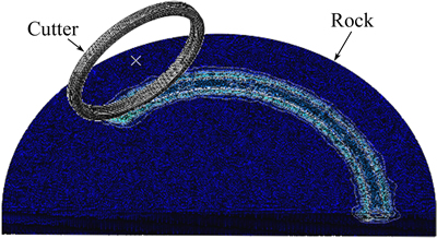
Fig. 4 Numerical simulation models of rotary cutting
3.2 Analysis of simulation results
In the simulation process, the side load of the disc cutter is recorded, including the overall side force, the side force of inner side and outer side of the cutter ring (the direction from the center to the outside of the cutterhead is considered to be positive). When the installation radius is 76 mm and 343 mm with a penetration of 6 mm, the respective instantaneous side forces of inner side and outer side of the cutter ring are compared, as shown as Fig. 5. The side load fluctuates constantly due to the jump in the process of rock fragmentation. Figure 5(a) shows the force comparison between the inner side and the outer side of the cutter ring when the cutter installation radius is 76 mm, and the average force is 12.5 kN for the inner side and 0.84 kN for the outer side. The side force of the cutter as a whole points towards the outside of the cutterhead with a large value. As shown in Fig. 5(b), when the installation radius is 343 mm, the side force of the inner side decreases while that of the outer side increases compared with thecase of installation radius 76 mm. The side force of the inner side is 6.60 kN and that of the outer side is 2.28 kN, which indicates a decrease in their difference, but the side force of the cutter still points to the outside of the cutterhead. Cutters with different installation radii have diverse motion characteristics, leading to property variations in the interaction between the rock and the cutter. As the cutter installation radius gets smaller, the load difference between the two sides of the cutter ring becomes more obvious, and thus the side force of the cutter turns larger. When the installation radius of the cutter gets larger, the load difference between the two sides gradually decreases since the rotary action is weakened.
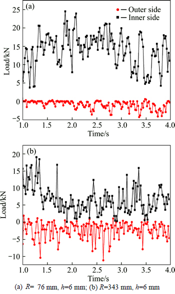
Fig. 5 Load comparison for both sides of cutter ring:
Figure 6 shows the comparison of the overall side force between cutters with an installation radius of 76 mm and 343 mm in penetration 6 mm and 8 mm. Though the side forces of both cutters show fluctuation due to jump rock fragmentation, they have different values. The side force of the cutter with an installation radius of 76 mm is larger than that of the cutter with an installation radius of 343 mm in the same penetration. For instance, the peak load of the side force for installation radius 76 mm in penetration 6 mm is 24.90 kN, and the average side force is 11.66 kN; the peak load of the side force for installation radius 343 mm in penetration 6 mm is 19.07 kN, and the average side force decreases to 4.32 kN.

Fig. 6 Variation of side force with time:
The side force with different installation radii in varied penetrations is illustrated in Fig. 7(a) for comparison and analysis. When the installation radius is small, the side force is quite large, but it decreases rapidly with the increase of the installation radius. The side forces of the two outermost center cutters the installation radii of which are bigger than 500 mm, are nearly the same with a small value. And the side force of the outermost center cutter in penetration 6 mm is only 0.74 kN. The side force of each center cutter increases with the increase of the cutter penetration, and the force difference in different penetrations becomes greater as the installation radius gets smaller. The opposite is true when the installation radius gets larger. The relation between the lateral rolling annulus width and the side force is built as shown in Fig. 7(b). When the annulus width is small, the side force is also small. Penetration in this stage has little effect on the side force. Yet the side force increases rapidly with the successive increase of the annulus width, and the difference of side forces in different penetrations gradually increases when the annulus width remains the same.

Fig. 7 Variation of simulative side force with cutter installation radius and lateral annulus width:
4 Similar experiment of rock fragmentation by disc cutter
The rotary cutting experiment platform is used to do experiments of the rock fragmentation process, and the similar 1:2 disc cutter is selected as the experiment cutter, with the concrete with a certain proportion poured into the material warehouse as the test object. The vertical cylinder thrusts the cutterhead to push the cutter into the concrete at a given depth, and the rotary motor drives the material warehouse to conduct rotary motion to complete the rock fragmentation process. The data of the cutter load can be monitored in real time and collected automatically by the 3-dimensional force sensor installed between the cutter carrier and the cutterhead, as shown in Fig. 8.
There are a set of bolt holes on the spokes of the cutterhead, and the change in the installation radius of the cutter can be achieved by altering the position of the installation bolt hole. Different groups of rock fragmentation simulation can be accomplished byaltering the penetration and the installation radius of the cutter. The concrete with shear strength 3.15 MPa is selected as the experiment object. Figure 9 shows the breaking effect of the concrete in different cutter penetrations. When the penetration is quite small, the cutter leaves a shallow trace on the concrete, and the breaking effects of the outer side and the inner side of the rock are nearly the same. However, when the penetration increases to 6 mm, the breaking effect of the concrete as a whole is quite desirable, and the breaking effect of the inner side is more evident than that of the outer side. Figure 10 depicts the curves of the side load changing with the time history. The cutter load displays a tendency of constant fluctuation, which is consistent with the jump property in the rock fragmentation process.

Fig. 8 Rotary cutting experiment platform of disc cutter

Fig. 9 Rock breaking with rotary cutting:
The value calculated by applying the shear theory is the average side force, whereas the actual rock fragmentation load is a kind of load fluctuating constantly, and some peak load is often 2 to 3 times of the average load. Some experimental data of the concrete cutting process are listed in Table 3. A comparison of the experimental data with the theoretical data reveals that the maximum error of the side force is 33.4% and the standard error is 124.8. As the experimental data exhibit certain discreteness and randomness due to the characteristics of rock materials, errors can hardly be avoided. Overall, the calculated values of the prediction model coincide with the experimental data.

Fig. 10 Experimental curve of side force:
Table 3 Comparison of theoretical and experimental side force

5 Conclusions
For the TBM center cutter, the formation mechanism and change law of the side force are studied during the rotary cutting process based on numerical simulation and rotary cutting experiments. The conclusions are as follows:
1) The inner side of the center cutter can form lateral rolling annuli in the rock during the rotary cutting process, and the annulus width varies with the installation radius. The smaller the installation radius is, the larger the width will be. In penetration 6 mm, the innermost center cutter forms a lateral rolling annulus with a width of 15.28 mm, while the outermost one with a width of 1.84 mm.
2) The load on the inner side of the cutter is larger than that on the outer side, and thus the cutter bears a side force towards the outside direction. The smaller the installation radius is, the larger the side force becomes. The side force is substantial when the installation radius is smaller than 500 mm. However, it decreases sharply with the increase of the installation radius, and tends to be gentle after the installation radius is larger than 500 mm. In a working condition, the side force of the innermost center cutter is 11.66 kN, while the side force of the outermost center cutter decreases to 0.74 kN.
References
[1] ROBY J, SANDELL T, KOCAB J, LINDERBERGH L. The current state of disc cutter design and development directions [C]// Proceeding of 2008 North American Tunneling Conference. San Francisco, USA: SME C, 2008: 36-45.
[2] SONG Ke-zhi, WANG Meng-shu. Analysis of the operation characteristics of tunnel boring machine in complex rocks [J]. China Civil Engineering Journal, 2012, 45(5): 176-181. (in Chinese)
[3] LIU H Y, KOU S Q, LINDQVIST P A, TANG C A. Numerical modeling of the heterogeneous rock fracture process using various test techniques [J]. Rock Mechanics and Rock Engineering, 2007, 40(2): 107-144.
[4] WANG S Y, SLOAN S W, LIU H Y, TANG C A. Numerical simulation of the rock fragmentation process induced by two drill bits subjected to static and dynamic (impact) loading [J]. Rock Mechanics and Rock Engineering, 2011, 44(3): 317-332.
[5] TAN Qing, ZHANG Kui, XIA Yi-min, ZHANG Kui. Numerical study on mode of breaking rock by TBM cutter in two cutting orders [J]. Journal of Central South University: Science and Technology, 2012, 43(3): 940-946. (in Chinese)
[6] BALCI C, TUMAC D. Investigation into the effects of different rocks on rock cuttability by a V-type disc cutter [J]. Tunnelling and Underground Space Technology, 2012, 30: 183-193.
[7] JI Chang-ming, ZHANG Zhao-huang, YE Ding-hai. The influence of the disc cutter space on rock’s jump break coefficients [J]. Journal of Basic Science and Engineering, 2008, 16(2): 255-263. (in Chinese)
[8] GERTSCH R, GERTSCH L, ROSTAMI J. Disc cutting tests in Colorado Red Granite: Implications for TBM performance prediction [J]. International Journal of Rock Mechanics&Mining Sciences, 2007, 44(2): 238-246.
[9] MOON T, OH J. A study of optimal rock-cutting conditions for hard rock TBM using the discrete element method [J]. Rock Mechanics and Rock Engineering, 2012, 45(5): 837-849.
[10] ROSTAMI J. Study of pressure distribution within the crushed zone in the contact area between rock and disc cutters [J]. International Journal of Rock Mechanics and Mining Sciences, 2013, 57: 172-186.
[11] ROSTAMI J. Development of a force estimation model for rock fragmentation with disc cutters through theoretical modeling and physical measurement of crushed zone pressure [D]. Golden, USA: Colorado School of Mines, 1997.
[12] XIA Yi-min, OUYANG Tao, CHEN Lei, LUO De-zhi, ZHANG Xin-ming. Study on the influencing factors of the disc cutter performance [J]. Journal of Basic Science and Engineering, 2012, 20(3): 500-507. (in Chinese)
[13] XIA Yi-min, OUYANG Tao, ZHANG Xin-ming, LUO De-zhi. Mechanical model of breaking rock and force characteristic of disc cutter [J]. Journal of Central South University, 2012, 19: 1846-1852.
[14] HUO Jun-zhou, YANG Jing, SUN Wei, LI Qing-yu. Simulation and optimization design of three-dimensional rotating cutting action of TBM cutter group with different modes [J]. Journal of Harbin Engineering University, 2014, 35(11): 1403-1408. (in Chinese)
[15] CHIKAOSA T, SHUNICHIRO Y, KIMIKAZU T. A study on cutter wear and mechanical properlies of rocks in tunneling with a TBM [J]. Journal of the Society of Materials Science, 2006, 55(1): 29-36.
(Edited by FANG Jing-hua)
Foundation item: Project(2013CB035401) supported by the National Basic Research Program of China; Project(51475478) supported by the National Natural Science Foundation of China; Project(2012AA041803) supported by the High-Tech Research and Development Program of China
Received date: 2015-03-13; Accepted date: 2015-07-22
Corresponding author: XIA Yi-min, Professor, PhD; Tel: +86-731-88876926; E-mail: xiaymj@csu.edu.cn

