����Ħ������ͭǶ����6061-T6���Ͻ�(Al/Cu/Al)������֯����ѧ����
��Դ�ڿ����й���ɫ����ѧ��(Ӣ�İ�)2018���3��
�������ߣ�Vahid M. Khojastehnezhad Hamed H. Pourasl
����ҳ�룺415 - 426
�ؼ��ʣ�����Ħ�����ӣ�Al/Cu/Al�������仯�������֯����ѧ����
Key words��friction stir welding; Al/Cu/Al; intermetallic compounds; microstructure; mechanical properties
ժ Ҫ�������� 6061-T6 ���м�Ƕ��һ�鴿ͭ��(Al/Cu/Al)�����ý���Ħ����(FSW)�������ϣ��о�ͭ�����Ժ��ӽ�ͷ���ܵ�Ӱ�죬������ͭ��Ľ���Ħ����AA 6061 (Al/Al)���о�������бȽϡ��ù�ѧ������ɨ��羵�۲캸����Ʒ������֯����X�����������Al/Cu/Al��Ʒ������ɡ���ת��Ϊ1000 r/min�ͺ����ٶ�Ϊ25 mm/min�����¹۲쵽Al/Cu/Al���ӽ�ͷ��ȱ�ݡ�������������֯�۲�����ʾ���Ƹ�����ṹ���γɴٽ�������ͭ��ұ���ϡ�XRD�����ʾ�γ��˽����仯���� (IMCs)����Al4Cu9��Al2Cu����������ߵ�λ���ܶȣ���Cu��ĺ�����Ʒ��Ӳ�Ƚϸߣ���IMCs���ڵ�������Ӳ��ֵ���Ը��ߡ���������֮ͭ���ǿ��ұ���ϣ���ͭ��ĺ��ӽ�ͷ�ļ�����ǿ�ȱ���ͭ��Ľ�ͷ���ߡ�
Abstract: Friction stir welding was used to join two aluminum 6061-T6 plates with an insert of a pure copper plate (Al/Cu/Al), and then the influence of the copper insert on the joint performance was studied. The dissimilar welding results were also compared with AA 6061 friction stir welds produced without copper insert (Al/Al). Optical and scanning electron microscopes were used for the microstructural observations of the welded samples. X-ray diffraction analysis was used to analyze phase component of the Al/Cu/Al specimen. A defect-free joint was observed for the Al/Cu/Al joint at a rotational speed of 950 r/min and a welding speed of 50 mm/min. Microstructural observation of the weld nugget zone (WNZ) demonstrates the formation of composite-like structure which promotes metallurgical bonding of aluminum and copper. XRD results show the formation of intermetallic compounds (IMCs), such as Al4Cu9 and Al2Cu. Furthermore, it was observed that the hardness of the weld with the Cu insert plate is higher than that of other samples due to more dislocation density and a distinct rise in hardness values was observed due to the presence of IMCs. The ultimate tensile strength of the joint with copper insert plate is higher than that of the other sample due to the strong metallurgical bonding between Al and Cu.
Trans. Nonferrous Met. Soc. China 28(2018) 415-426
Vahid M. Khojastehnezhad, Hamed H. Pourasl
Department of Mechanical Engineering, Eastern Mediterranean University, Famagusta 99628, TRNC, Via 10, Mersin, Turkey
Received 28 February 2017; accepted 20 July 2017
Abstract: Friction stir welding was used to join two aluminum 6061-T6 plates with an insert of a pure copper plate (Al/Cu/Al), and then the influence of the copper insert on the joint performance was studied. The dissimilar welding results were also compared with AA 6061 friction stir welds produced without copper insert (Al/Al). Optical and scanning electron microscopes were used for the microstructural observations of the welded samples. X-ray diffraction analysis was used to analyze phase component of the Al/Cu/Al specimen. A defect-free joint was observed for the Al/Cu/Al joint at a rotational speed of 950 r/min and a welding speed of 50 mm/min. Microstructural observation of the weld nugget zone (WNZ) demonstrates the formation of composite-like structure which promotes metallurgical bonding of aluminum and copper. XRD results show the formation of intermetallic compounds (IMCs), such as Al4Cu9 and Al2Cu. Furthermore, it was observed that the hardness of the weld with the Cu insert plate is higher than that of other samples due to more dislocation density and a distinct rise in hardness values was observed due to the presence of IMCs. The ultimate tensile strength of the joint with copper insert plate is higher than that of the other sample due to the strong metallurgical bonding between Al and Cu.
Key words: friction stir welding; Al/Cu/Al; intermetallic compounds; microstructure; mechanical properties
1 Introduction
Aluminum and copper have been extensively utilized as industrial structure materials due to their distinctive properties, such as formability and ductility, corrosion resistance, heat transfer and electrical conductivity [1,2]. Aerospace, automotive and electronic industries have used numerous mixture components specifically for the aluminum/copper (Al/Cu) metallic combination which proves the significant mechanical properties [3,4]. However, a dissimilar joining of aluminum and copper is commonly problematic due to excessive dissimilarity in their physical and chemical properties [5-7]. Fusion welding technique has been used to create dissimilar joint between Al and Cu, but some problems happened such as solidification cracking, oxidation and formation of the undesirable amount of brittle Intermetallic compounds (IMCs) due to the high chemical affinity between Al and Cu, which resulted in poor mechanical properties [8-12]. Thus, some welding techniques such as explosive welding [13,14], diffusion bonding [15,16] and friction stir welding (FSW) have been established as unconventional welding methods for creating a joint between Al and Cu. FSW is a solid-state welding process developed by the welding institute (TWI) [17], which has been employed for welding of similar and dissimilar materials [18-25]. Generated temperature in this welding process is lower than the metal melting point which makes this method as a good candidate for welding dissimilar materials. Formation of the joint without any melting reduces the problems that occurs in the fusion welding. Therefore, many recent investigations have been done on the application of FSW in dissimilar joining between Al and Cu.
AKINLABI [26] studied the effect of welding parameters on the mechanical properties of joints between 5754 aluminum alloy (AA) and C11000 copper (Cu) generated with the friction stir welding process. He investigated the tensile strength using different welding parameters such as tool size, rotational speed and traverse speed. The results indicated that the joint created had joint efficiency of 86% when the rotation rate is 950 r/min and feed rate is 50 mm/min with the 18 mm shoulder diameter tool, which can be satisfactory for design objectives. The X-ray diffraction analysis revealed the presence of Al4Cu9 and Al2Cu intermetallics at the stir zone. AKINLABI [26] also reported that a good material flow was obtained in welds generated at lower feed rate owing to high heat generated whereas the welds created at high feed rates led to worm hole defect formation. LIU et al [27] investigated the microstructural and mechanical properties in the friction stir welded 5A06 aluminum alloy to copper (T2). They found that the maximum ultimate tensile strength (UTS) obtained in FS welds of aluminum and copper was approximately 296 MPa when the tool rotational speed is 950 r/min, and the feed rate is 150 mm/min. XUE et al [28] studied the microstructural and mechanical properties of friction stir welded aluminum/ copper joints. It is observed that FSW Al/Cu joints failed in the HAZ of the Al side with a 13% of elongation. The yield strength and the ultimate tensile strength (UTS) were ~80% and ~90% of the Al base material respectively. However, in some specimens the fracture was located in particle-rich zone (PRZ), and the UTS was nearby 210 MPa which was much higher than Al base metal. LI et al [29] investigated the microstructural and mechanical properties in the friction stir welded 1350 aluminum alloy to pure copper. They reported that the hardness increased obviously in the stir zone due to the strengthening effect of the Al/Cu intermetallic compounds. Furthermore, they observed that the hardness at the lower region of the nugget zone is mostly higher than other regions owing to the intense stirring action of the tool pin which led to recrystallized grains. The UTS of the dissimilar joint was 152 MPa with 6.3% elongation, and the joint fractured in a ductile-brittle mixed fracture mode. AKINLABI et al [30] studied the influence of heat input on the mechanical properties of joints between aluminum and copper generated with the friction stir welding process. The joints were fabricated using different welding parameters in order to vary the heat input to the welds. The microstructural observation revealed that good metallurgical bonding was achieved at the joint interfaces of the welds produced. Higher Vickers microhardness values were observed at the joint interfaces resulting from strain hardening and the existence of intermetallics.
The purpose of the study is to introduce a new approach to the welding processes by incorporating characteristic features of composite structures with the similar weld joints. In order to fulfill this aim, the new approach of using Al/Cu/Al dissimilar weld joint has been utilized. Throughout this work, most of the references were made based on the dissimilar joining of Al and Cu. It has been thoroughly outlined that the mechanical properties of such welds are superior in terms of its tensile strength. However, the usage of this particular kind of welds is uncommon within the industries. On the other hand, Al/Al FSWed joint has been used for industrial application, especially in the circle of automotive and aerospace engineering. From our study, the similar Al/Al FSWed joint can be replaced with Al/Cu/Al joint for more optimum performance; since dissimilar joints have been proven to possess enhanced properties compared with similar joints and thus, will be able to withstand the loading conditions that these components will be subjected to on the field. Consequently, the essence of this study is to merge the desirable features of dissimilar welding with similar welding, which has more applications in the industries.
This work deals with the FSW process of AA6061 plates with and without the presence of copper inserts between the adjoining plates. Microstructure and mechanical analyses were performed to assess the influence of the copper insert on the joint performance. Many researchers have employed the FSW technique to weld similar and dissimilar materials, but this study presents a combination of the welding of two similar material plates (AL6061-T6) with a different material plate (copper) between them, by which a similar technique was conducted before using FSW as a weld marker technique for flow visualization in FSW, but there is a no attempt to investigate the mechanical properties. The hybrid welded sheet can be used in processes where higher tensile strength is required.
The properties of a joint, generated by FSW are directly related to the material flow around the tool. Several flow visualization studies in FSW have been conducted using a weld marker technique. This technique is based on the use of marker materials for tracing the material flow during welding. SCHMIDT et al [31] studied flow visualization in butt friction stir welds in AA2024-T3 via introducing a thin copper strip between the workpieces as a marker material as shown in Fig. 1. The material flow is visualized via the distribution of the Cu particles in the stir zone. SEIDEL et al [32] observed the visualization of the material flow in AA 2195 friction stir welds using a marker insert technique. AA5454-H32 thin strips were inserted into the faying surface of the two plates to be welded. Result shows the full three-dimensional plots of the distorted markers description which affords a good qualitative description of material flow in this welding. Moreover, DICKERSON et al [33] used a weld marker technique for flow visualization. Copper strips of 0.1 mm in thickness were inserted as a marker material in various series of aluminum alloys.
2 Experimental
The materials studied were 6061-T6 aluminum alloy and pure copper (T2), both with thickness of 5 mm. The chemical compositions of the Al and Cu are listed in Tables 1 and 2. The dimensions of Al plates were 150 mm �� 75 mm, and the Cu plate was cut into 150 mm �� 1 mm. Additionally, pure copper was annealed at approximately 700 ��C and maintained for 1 h and then cooled in air. The oxide film on the surfaces of the sheets was removed using grit paper and then cleaned via acetone. A cylindrical tool pin with thread was produced from H13 steel with a shoulder diameter of 16 mm, a pin diameter of 5 mm, and a pin length of 4.8 mm [34,35]. Vertical milling machine was used to generate samples. The joints were fabricated at a rotational speed of 950 r/min and feed rate of 50 mm/min, and tilt angle of the tool was 3��. FSW parameters and tool specification used in this study are listed in Table 3. The specimens were cut perpendicular to the direction of welding. For microstructural observation, the specimens were ground down using 12 series abrasive papers from 150 to 2000 grit and then were etched in the etching solution which included 25 mL EtOH + 35 mL HNO3 +25 HCl +3 mL HF. Optical microscopy (OM) and field emission scanning electron microscopy (FE-SEM) were used to carry out microstructural characterization. The phase component was characterized by X-ray diffraction (XRD) using Cu K�� radiation at 40 kV and 30 mA. The Vickers microhardness test was applied at upper, middle and lower regions of the cross section with a load of 50 g for 15 s. The tensile test was performed using the universal testing machine (AG-5000A). In addition, as demonstrated in Fig. 2, the pure copper plate was placed between 6061-T6 aluminum plates and the tool pin was located in the middle of the multilayer plates, and Fig. 3 shows the shape and dimension of the used tool.
3 Result and discussion
3.1 Macrostructure of joints
The surface appearance of the joint is shown in Fig. 4(a) which illustrates a defect-free surface without any crack or hole and groove. Also, the machined surface of the joint illustrates same features as shown in Fig. 4(b). However, defect-free joint can be obtained by controlling welding parameters such as rotational rate of the tool, welding speed and dwell time of the tool. For achieving perfect joint, the high rotational speed of the tool and low welding speed are generally needed. Consequently, the surface defects were observed at rotational speeds less than 800 r/min and a feed rate more than 80 mm/min, which cannot generate enough heat input to achieve good material flow for generating defect-free joint [26,27,36]. Moreover, dwell time of the tool is an essential factor to achieve a sufficient heat input. However, very high rotational rate leads to an extreme heat input level, which causes the grains to grow on the structure of the joint and increases the amount of intermetallic compound at the Al-Cu interface which results in undesirable mechanical properties [36]. Furthermore, the tool shaking was another problem during welding process which could be unconcerned via the annealing softening of the copper plate before FSW [37].
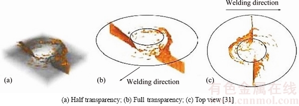
Fig. 1 3D CT model of sample with different transparencies (Gray is aluminium and yellow is copper)
Table 1 Chemical composition of 6061-T6 aluminum alloy (mass fraction, %)

Table 2 Chemical composition of copper (T2) (mass fraction, %)

Table 3 FSW parameters and tool specification used in this study
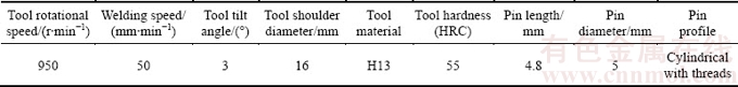
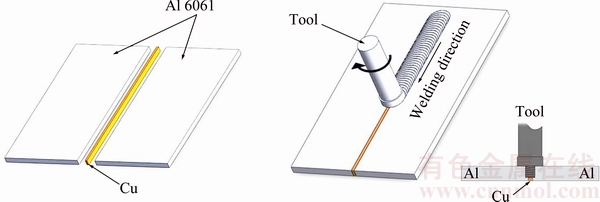
Fig. 2 Schematic diagram of Al/Cu/Al dissimilar FSW
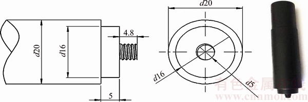
Fig. 3 Dimension and shape of FSW tool pin (unit: mm)
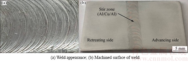
Fig. 4 Macrograph of weld (Al/Cu/Al) surface
Figures 5(a) and (b) show the macrostructures of the nugget zone of the FSW joints with and without the copper insert plate, respectively. According to Fig. 5(a), there are no defects, such as cavities and cracks in the cross-sectional macrograph showing perfect mixing between Al and Cu. Mostly, Cu particles were found on the advancing side of the joint as shown in Fig. 5(a). The mixed structure of the Al-Cu was observed in the nugget zone which was called intercalation swirls. The usual cross section of the weld indicates obviously differently affected zones in both samples, such as stirred zone (SZ), heat affected zone (HAZ) and thermo- mechanically affected zone (TMAZ). Additionally, the typical onion ring pattern was shown in the nugget zone due to good material flow, which illustrates enough heat input [38].
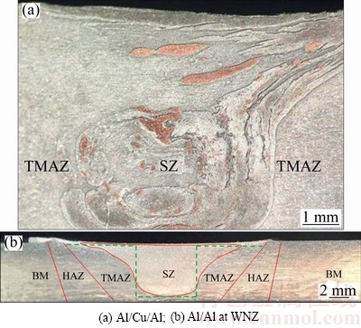
Fig. 5 Macrostructures of cross section of joints
3.2 Microstructure of Al/Cu/Al joint
Figure 6 shows the optical micrographs of the nugget region of the weld (Al/Cu/Al). Figures 6(a, b) indicate big pieces of Cu in the upper section of the weld and the apparent boundary between aluminum (Al) and copper (Cu) layers is displayed. Figures 6(c, d, e, f) indicate the distribution of Cu layers and fragments in the middle and lower sections of the weld respectively, which shows smaller Cu fragments and layers compared with the upper section. In addition, the plastic mixture of Al-Cu is shown in nugget zone, which illustrates lamellar alternating structure [27,29]. The Cu particles and layers with irregular shapes and different sizes were distributed in nugget zone. The stir act and heat input of the tool and different heat conductivities of Al and Cu resulted in the formation of different structures of both materials (Al-Cu) in stir zones such as Cu bulks, Cu layers and Cu particles and a mixed structure which were indicated by arrows in Fig. 6. The size of each layer is not more than a few micrometers, which shows that the characteristics of the mixed structure including certain mechanical mixing and metallurgical bonding had occurred between both materials [28,30].
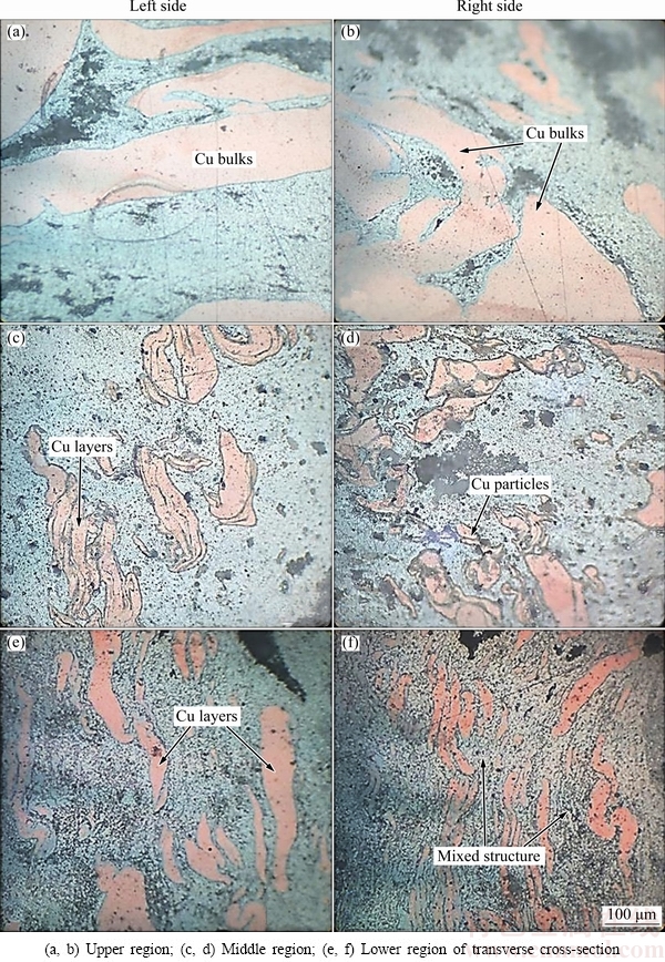
Fig. 6 Microstructures of Al/Cu/Al joint at WNZ
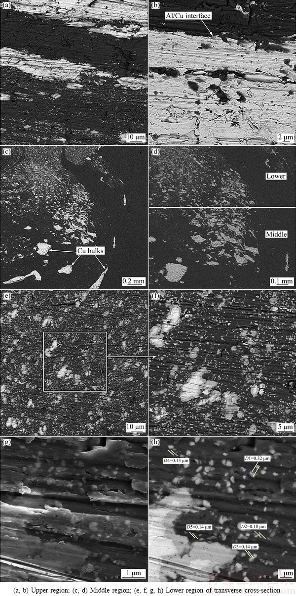
Fig. 7 SEM images of Al/Cu/Al joint at WNZ
Figure 7 indicates the microstructures of dissimilar joint. The micrographs were carried out at secondary electrons (SE) and backscattered electrons (BSE) modes.
Figures 7(a, b) show coarse Cu bulks in the upper section of the joint. The interface of Al-Cu was clearly observed and also some Al particles were identified in the Cu bulk. The intense stirring action was shown in the lower section of the joint in Figs. 7(c, d), which produced intercalation and swirl-like pattern structure in the WNZ. Smaller Cu particles and fragments were dispersed uniformly in the nugget zone, especially in lower and middle sections of the joint due to good material flow as shown in Figs. 7(c, d). The presence of Cu particles and fragments with different sizes and irregular morphology into the Al matrix resulted in the formation of composite-like structure. Likewise, a similar occurrence was reported by XUE et al [28]. Dispersion of Cu particles into the Al matrix acts as a strengthening mechanism based on precipitation hardening. Furthermore, Fig. 7(g) illustrates that a large amount of nano-scaled Cu particles were dispersed into lower and middle sections of the nugget zone, and some Cu fragments were observed in this region, but their size and amount were less than the upper region of the joint.
During FSW, the rotation of the pin tool generates a pressure (P) which is applied in the direction perpendicular to the thread surface of the tool, and also the friction generated between plasticized material and thread surface of the tool produces a traction force (T), which is parallel to the thread surface [39]. These forces are applied to the plasticized material around the tool pin as shown in Fig. 8. The presence of the action of the pressure and traction forces combined with the use of a right hand threaded pin tool in a clockwise rotation leads to transportation of the plasticized material upward from the bottom of the joint. Therefore, the direction of the material flow is directed upwards from the bottom of the weld. Therefore, the intense stirring action was experienced by the lower section of the weld as shown in Fig. 5(a). Thus, Cu bulks are fragmentized into smaller particles in this section of the joint.
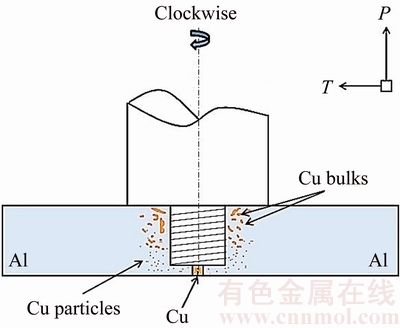
Fig. 8 Schematic diagram of Al/Cu/Al dissimilar FSW
The phase fraction of the joint with Cu plate is shown in Fig. 9. The blue area indicates aluminum and red area is copper. The upper, middle and lower regions of the joint were analyzed. Results indicate the uniform distribution of smaller Cu particles in the lower section of the weld compared with other regions. Moreover, particle size analysis was performed for Cu particles in stir zone. Nano-scaled Cu particles in the lower section of the joint showed more Cu grain refinement than the other regions, as shown in Fig. 7(g).
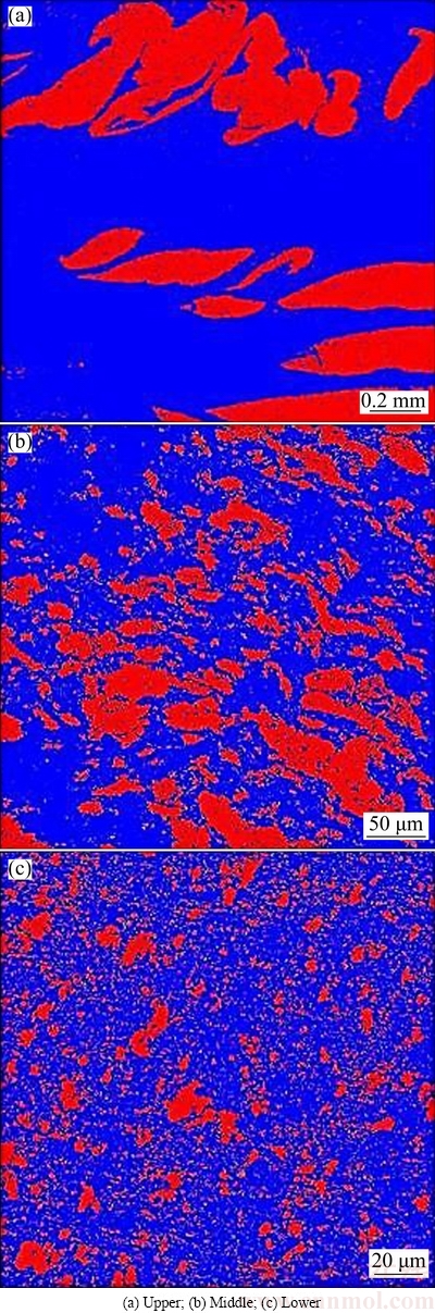
Fig. 9 Phase fraction of Al/Cu/Al joint in different regions
The phase distribution in the nugget zone is displayed in Fig. 10. Results show a good mixing of Al and Cu in nugget zone of the weld. According to the element distribution of Al and Cu, the apparent red clustered particles in Fig. 10(c) mostly contained Cu bulks marked by arrows in Figs. 10(a, b). The refined Cu particles and fragments were dispersed into the Al matrix which resulted in the formation of composite-like structure based on the microstructural observation in Fig. 7(e). Also, the minor variation of color difference in Figs. 10(a) and (b) demonstrate interfacial diffusion and reaction between both materials, which resulted in the formation of the Al/Cu IMCs in this zone.
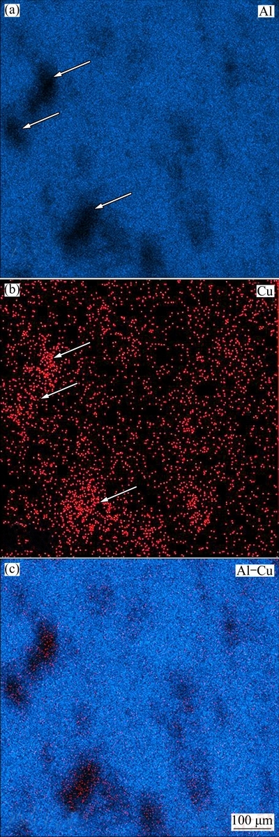
Fig. 10 EDS mappings of Al/Cu/Al joint at WNZ
3.3 XRD analysis
Figure 11(a) indicates the X-ray diffraction patterns of the joint with Cu insert plate. The generated phases are shown by diffraction patterns. The result shows the presence of Al and Cu elements and formation of the IMCs or reaction layers such as Al4Cu9 and Al2Cu in nugget zone of the joint [26,28,40]. Figures 11(b, c) show the SEM images of the nugget zone of the Al/Cu/Al joint. The results show the formation of the reaction layers (IMCs) at the Al-Cu interface. It can be obviously seen that the width of the reaction layers is less than 1 ��m. These nano-scaled reaction layers have a notable effect on mechanical properties of the Al/Cu/Al joint. An undesirable amount of IMCs was generated in traditional fusion welding due to the high chemical affinity between Al and Cu, which resulted in poor mechanical properties [41]. During FSW, the generated temperature was lower than the melting point of Al and Cu, which limited the problems of fusion welding [41, 42]. In other words, the formation of reaction layers in FSW could be in lower heat input than that desired in fusion welding, thus the amount of IMCs can be controlled. But in some studies, just composite- like structure was formed in the Al/Cu joint, and there are no IMCs layers which could be associated with the heat input. High welding speed generates low heat input which is not enough to create the interfacial reaction between Al and Cu. On the other hand, the amount of reaction layers was increased at the low welding speed.
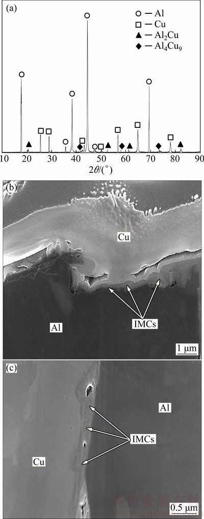
Fig. 11 XRD pattern of Al/Cu/Al joint (a) and SEM images (b, c) of IMCs formed at Al-Cu interface
3.4 Mechanical properties
3.4.1 Microhardness distribution
Figure 12 shows the Vickers microhardness allocation on the transverse cross-section of the joint with Cu plate along upper, middle, and lower regions of the welded plates and the sample without Cu plate. The hardness values of Al plates and Cu insert plate were HV 109 and HV 98, respectively. The results illustrate that the hardness in the stir zone of the welded joint is obviously higher than other regions and the base Al matrix. Different hardness values were discovered in the nugget zone of the joint. HAZ region shows lower hardness than that of the base metal due to HAZ softening [43]. The dynamic recrystallization in nugget zone resulted in the formation of very fine recrystallized grains in this region which could be a reason for the hardness increment. In addition, intense plastic deformation in nugget zone increases dislocation density and grain boundaries, which resulted in short-circuit diffusion. Thus, the formation of IMCs can be accelerated, which shows the highest hardness value. The results show higher hardness values at lower and middle regions of the nugget zone in comparison to the upper region, due to the formation of IMCs in these regions and the intense stirring action of the tool pin which led to recrystallized grains [29]. The highest hardness values HV 210 and HV 199 were observed in lower and middle regions of the nugget zone respectively, which can be attributed to the existence of nano-scaled IMCs. The results show that the hardness in the HAZ of 6061-T6 Al can be 20% less than the parent metal, with the WNZ showing a 15% decrease in hardness. These results show that the hardness of the nugget zone was independent of the grain size considering the Hall�CPetch relation [44]. Therefore, the mechanical properties of the nugget zone can be related to other factors, such as precipitations and dislocation density [45,46].
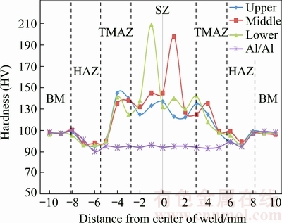
Fig. 12 Hardness profiles along upper, middle and lower regions of cross section of Al/Cu/Al joint and hardness of Al/Al joint
3.4.2 Tensile strength and fracture behavior
Figure 13 indicates the size and position of the tensile test specimen. The ultimate tensile strength (UTS) of the joint with copper insert plate and the welded joint without Cu insert plate is shown in Fig. 14. The average ultimate tensile strengths of the base metals Al and Cu were 320 and 225 MPa respectively. Additionally, the ultimate tensile strength of the joint with copper plate reached 285 MPa, indicating the joint efficiency of 89.1% of the Al base metal. While, for the joint welded without Cu plate the tensile strength was 218 MPa with 73.5% of joint efficiency. Figure 15 shows the fracture location of the joints with and without Cu insert plate. The fracture of the joint without Cu insert plate was located in the stir zone close to the Al-Al interface following the zigzag pattern and crack propagation, which was extended to the weld centerline. The fracture location of the joint with Cu insert plate was in the thermo-mechanically affected zone (TMAZ) close to Al plate and the crack transition was extended into TMAZ close to Al plate in middle and lower sections. The existence of IMCs and composite-like structure act as a resistance to crack propagation in these zones.
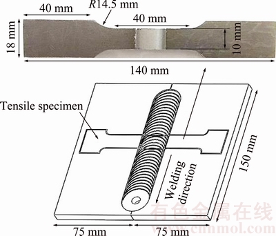
Fig. 13 Schematic diagram of tensile specimen position on joints
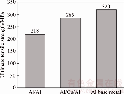
Fig. 14 Ultimate tensile strength of joints and Al base metal
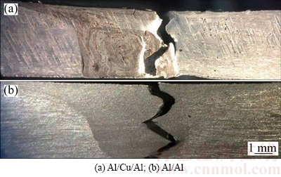
Fig. 15 Fracture location of joints
Figure 16 shows the SEM images of fracture surface of the joints generated with and without Cu insert plate. It can be seen from Figs. 16(a, b) that no dimples and some smooth surface with a few deformations were formed as a feature on the fracture surface for the sample without Cu plate. However, in Figs. 16(c, d) the fracture morphology of the joint with Cu insert plate illustrates dimples or micro voids in different sizes and little featureless surfaces such as flat and smooth surfaces were observed. The presence of fine Cu inclusions in nugget zone of the joint led to the formation of dimples in this region and these particles act as a strengthening particle for avoiding crack propagation. Cu layers and precipitations were indicated by the arrow in Fig. 16(d).
4 Conclusions
1) 6061-T6 aluminum plates with copper insert plate was successfully joined using FSW process at rotation rate of 1000 r/min and welding speed of 25 mm/min. High rotation speed and low welding speed were needed to generate defect-free joint.
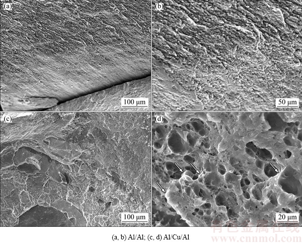
Fig. 16 SEM images of fracture surface of joints
2) Intercalation swirl and lamellar alternating structure were observed in WNZ. Cu balks and layers were fragmentized into fine particles. The distribution of the Cu particles and fragments in Al matrix resulted in the formation of composite-like structure. The intense stirring act was observed in the lower region of the joint, which produced intercalation structure. High plastic deformation in WNZ enables short-circuit diffusion, which accelerates the formation of IMCs.
3) The XRD results show Al and Cu elements and formation of IMCs or reaction layers such as Al4Cu9 and Al2Cu in WNZ. The presence of these reaction layers is the main reason for the distinct rise in hardness value.
4) The formation of very fine recrystallized grains and high dislocation density is a main reason for the hardness enhancement in WNZ. The presence of IMCs and composite-like structure causes a strong metallurgical bond between Al and Cu and improves the mechanical strength. The ultimate tensile strength of the joint with Cu insert plate is 285 MPa, indicating the joint efficiency of 89.1% of the Al base metal which is higher than the joint produced without Cu plate.
References
[1] FENG J I, XUE S B, LOU J Y, LOU Y B, WANG S Q. Microstructure and properties of Cu/Al joints brazed with Zn-Al filler metals [J]. Transactions of Nonferrous Metals Society of China, 2012, 22(2): 281-287.
[2] WEIGL M, ALBERT F, SCHMIDT M. Enhancing the ductility of laser-welded copper-aluminum connections by using adapted filler materials [J]. Physics Procedia, 2011, 12: 332-338.
[3] SIMONCINI M, FORCELLESE A. Effect of the welding parameters and tool configuration on micro-and macro-mechanical properties of similar and dissimilar FSWed joints in AA5754 and AZ31 thin sheets [J]. Materials & Design, 2012, 41: 50-60.
[4] BANG H, BANG H, JEON G, OH I, RO C. Gas tungsten arc welding assisted hybrid friction stir welding of dissimilar materials Al6061-T6 aluminum alloy and STS304 stainless steel [J]. Materials & Design, 2012, 37: 48-55.
[5]  I, VERDERA D, GESTO D, LOUREIRO A, RODRIGUES D M. Influence of aluminium alloy type on dissimilar friction stir lap welding of aluminium to copper [J]. Journal of Materials Processing Technology, 2013, 213(11): 1920-1928.
[6] OUYANG Jia-hu, YARRAPAREDDY E, KOVACEVIC R. Microstructural evolution in the friction stir welded 6061 aluminum alloy (T6-temper condition) to copper [J]. Journal of Materials Processing Technology, 2006, 172.1: 110-122.
[7] ZHANG J, SHEN Y, YAO X, XU H, LI B. Investigation on dissimilar underwater friction stir lap welding of 6061-T6 aluminum alloy to pure copper [J]. Materials & Design, 2014, 64: 74-80.
[8] TAN C W, JIANG Z G, LI L Q, CHEN Y B, CHEN X Y. Microstructural evolution and mechanical properties of dissimilar Al-Cu joints produced by friction stir welding [J]. Materials & Design, 2013, 51: 466-473.
[9] LIU P, SHI Q, WANG W, WANG X, ZHANG Z. Microstructure and XRD analysis of FSW joints for copper T2/aluminium 5A06 dissimilar materials [J]. Materials Letters, 2008, 62(25): 4106-4108.
[10] MOZHAISKAYA T M, CHEKANOVA N T. Structure and properties of welded aluminum-copper joints [J]. Metal Science and Heat Treatment, 1990, 32(12): 938-939.
[11] TORKAMANY M J, TAHAMTAN S, SABBAGHZADEH J. Dissimilar welding of carbon steel to 5754 aluminum alloy by Nd: YAG pulsed laser [J]. Materials & Design, 2010, 31(1): 458-465.
[12] ZHAO Y, LU Z, YAN K, HUANG L. Microstructural characterizations and mechanical properties in underwater friction stir welding of aluminum and magnesium dissimilar alloys [J]. Materials & Design, 2015, 65: 675-681.
[13] ASEMABADI M, SEDIGHI M, HONARPISHEH M. Investigation of cold rolling influence on the mechanical properties of explosive- welded Al/Cu bimetal [J]. Materials Science and Engineering A, 2012, 558: 144-149.
[14] CHEN S Y, WU Z W, LIU K X, LI X J, LUO N, LU G X. Atomic diffusion behavior in Cu-Al explosive welding process [J]. Journal of Applied Physics, 2013, 113.4: 044901.
[15] XIA C, LI Y, PUCHKOV U A, GERASIMOV S A, WANG J. Microstructure and phase constitution near the interface of Cu/Al vacuum brazing using Al-Si filler metal [J]. Vacuum, 2008, 82(8): 799-804.
[16] ESLAMI P, TAHERI A K. An investigation on diffusion bonding of aluminum to copper using equal channel angular extrusion process [J]. Materials Letters, 2011, 65(12): 1862-1864.
[17] THOMAS W M, NICHOLAS D, NEEDHAM J C, MURCH M G, TEMPLESMITH P, DAWES C J. Friction Stir Welding, International Patent Application No. PCT/GB92/02203, 1991[P].
[18] YONG Y, ZHANG D T, CHENG Q I U, ZHANG W. Dissimilar friction stir welding between 5052 aluminum alloy and AZ31 magnesium alloy [J]. Transactions of Nonferrous Metals Society of China, 2010, 20: s619-s623.
[19] CHEN Yu-hua, QUAN N I, KE Li-ming. Interface characteristic of friction stir welding lap joints of Ti/Al dissimilar alloys [J]. Transactions of Nonferrous Metals Society of China, 2012, 22(2): 299-304.
[20] MEHTA KUSH P, BADHEKA V J. Influence of tool pin design on properties of dissimilar copper to aluminum friction stir welding [J]. Transactions of Nonferrous Metals Society of China, 2017, 27(1): 36-54.
[21] TANAKA T, MORISHIGE T, HIRATA T. Comprehensive analysis of joint strength for dissimilar friction stir welds of mild steel to aluminum alloys [J]. Scripta Materialia, 2009, 61(7): 756-759.
[22] SOMASEKHARAN A C, MURR L E. Characterization of complex, solid-state flow and mixing in the friction-stir welding (FSW) of aluminum alloy 6061-T6 to magnesium alloy AZ91D using color metallography [J]. Journal of Materials Science, 2006, 41(16): 5365-5370.
[23] CHEN Y C, NAKATA K. Microstructural characterization and mechanical properties in friction stir welding of aluminum and titanium dissimilar alloys [J]. Materials & Design, 2009, 30(3): 469-474.
[24] LEE Won-Bae, YEON Yun-Mo, JUNG Seung-Boo. The joint properties of dissimilar formed Al alloys by friction stir welding according to the fixed location of materials [J]. Scripta Materialia, 2003, 49(5): 423-428.
[25] KOSTKA A, COELHO R S, DOS S J, PYZALLA A R. Microstructure of friction stir welding of aluminium alloy to magnesium alloy [J]. Scripta Materialia, 2009, 60(11): 953-956.
[26] AKINLABI E T. Effect of shoulder size on weld properties of dissimilar metal friction stir welds [J]. Journal of Materials Engineering and Performance, 2012, 21(7): 1514-1519.
[27] LIU P, SHI Q, WANG W, WANG X, ZHANG Z. Microstructure and XRD analysis of FSW joints for copper T2/aluminium 5A06 dissimilar materials [J]. Materials Letters, 2008, 62(25): 4106-4108.
[28] XUE P, XIAO B L, NI D R, MA Z Y. Enhanced mechanical properties of friction stir welded dissimilar Al-Cu joint by intermetallic compounds [J]. Materials Science and Engineering A, 2010, 527(21): 5723-5727.
[29] LI X W, ZHANG D T, QIU C, ZHANG W. Microstructure and mechanical properties of dissimilar pure copper/1350 aluminum alloy butt joints by friction stir welding [J]. Transactions of Nonferrous Metals Society of China, 2012, 22(6): 1298-1306.
[30] AKINLABI E T, AKINLABI S A. Effect of heat input on the properties of dissimilar friction stir welds of aluminium and copper [J]. American Journal of Materials Science, 2012, 2(5): 147-152.
[31] SCHMIDT H N B, DICKERSON T L, HATTEL J I. Material flow in butt friction stir welds in AA2024-T3 [J]. Acta Materialia, 2006, 54(4): 1199-1209.
[32] SEIDEL T U, REYNOLDS ANTHONY P. Visualization of the material flow in AA2195 friction-stir welds using a marker insert technique [J]. Metallurgical and Materials Transactions A, 2001, 32(11): 2879-2884.
[33] DICKERSON T, SHERCLIFF H, SCHMIDT H. A weld marker technique for flow visualization in friction stir welding [CJ]//4th International Symposium on Friction Stir Welding. Cambridge: TWI, 2003: 16.
[34] ABDOLLAH-ZADEH A, SAEID T, SAZGARI B. Microstructural and mechanical properties of friction stir welded aluminum/copper lap joints [J]. Journal of Alloys and Compounds, 2008, 460(1): 535-538.
[35] AKINLABI E T. Characterisation of dissimilar friction stir welds between 5754 aluminium alloy and C11000 copper [D]. Port Elizabeth, South Africa: Nelson Mandela Metropolitan University, 2011.
[36] BISADI H, TAVAKOLI A, SANGSARAKI M T, SANGSARAKI K T. The influences of rotational and welding speeds on microstructures and mechanical properties of friction stir welded Al5083 and commercially pure copper sheets lap joints [J]. Materials & Design, 2013, 43: 80-88.
[37] ZHANG Qiu-zheng, GONG Wen-biao, WEI L I U. Microstructure and mechanical properties of dissimilar Al-Cu joints by friction stir welding [J]. Transactions of Nonferrous Metals Society of China, 2015, 25(6): 1779-1786.
[38] KRISHNAN K N. On the formation of onion rings in friction stir welds [J]. Materials Science and Engineering A, 2002, 327(2): 246-251.
[39] CHOWDHURY S M, CHEN D L, BHOLE S D, CAO X. Tensile properties of a friction stir welded magnesium alloy: Effect of pin tool thread orientation and weld pitch [J]. Materials Science and Engineering A, 2010, 527(21): 6064-6075.
[40] GENEVOIS C, GIRARD M, HUNEAU B, SAUVAGE X, RACINEUX G. Interfacial reaction during friction stir welding of Al and Cu [J]. Metallurgical and Materials Transactions A, 2011, 42(8): 2290.
[41] LIU H J, SHEN J J, ZHOU L, ZHAO Y Q, LIU C, KUANG L Y. Microstructural characterisation and mechanical properties of friction stir welded joints of aluminium alloy to copper [J]. Science and Technology of Welding and Joining, 2011, 16(1): 92-98.
[42] POURALI M, ABDOLLAH-ZADEH A, SAEID T, KARGAR F. Influence of welding parameters on intermetallic compounds formation in dissimilar steel/aluminum friction stir welds [J]. Journal of Alloys and Compounds, 2017, 715: 1-8.
[43] SINGH R K R, SHARMA C, DWIVEDI D K, MEHTA N K, KUMAR P. The microstructure and mechanical properties of friction stir welded Al-Zn-Mg alloy in as welded and heat treated conditions [J]. Materials & Design, 2011, 32(2): 682-687.
[44] MORISADA Y, FUJII H, NAGAOKA T, FUKUSUMI M. MWCNTs/AZ31 surface composites fabricated by friction stir processing [J]. Materials Science and Engineering A, 2006, 419(1): 344-348.
[45] VATANKHAH BARENJI R, KHOJASTEHNEZHAD V M, POURASL H H, RABIEZADEH A. Wear properties of Al-Al2O3/ TiB2 surface hybrid composite layer prepared by friction stir process [J]. Journal of Composite Materials, 2016, 50(11): 1457-1466.
[46] HEIDARZADEH A, KHODAVERDIZADEH H, MAHMOUDI A, NAZARI A E. Tensile behavior of friction stir welded AA 6061-T4 aluminum alloy joints [J]. Materials & Design, 2012, 37: 166-173.
Vahid M. Khojastehnezhad, Hamed H. Pourasl
Department of Mechanical Engineering, Eastern Mediterranean University, Famagusta 99628, TRNC, Via 10, Mersin, Turkey
ժ Ҫ�������� 6061-T6 ���м�Ƕ��һ�鴿ͭ��(Al/Cu/Al)�����ý���Ħ����(FSW)�������ϣ��о�ͭ�����Ժ��ӽ�ͷ���ܵ�Ӱ�죬������ͭ��Ľ���Ħ����AA 6061 (Al/Al)���о�������бȽϡ��ù�ѧ������ɨ��羵�۲캸����Ʒ������֯����X�����������Al/Cu/Al��Ʒ������ɡ���ת��Ϊ1000 r/min�ͺ����ٶ�Ϊ 25 mm/min�����¹۲쵽Al/Cu/Al���ӽ�ͷ��ȱ�ݡ�������������֯�۲�����ʾ���Ƹ�����ṹ���γɴٽ�������ͭ��ұ���ϡ�XRD�����ʾ�γ��˽����仯���� (IMCs)����Al4Cu9��Al2Cu����������ߵ�λ���ܶȣ���Cu��ĺ�����Ʒ��Ӳ�Ƚϸߣ���IMCs���ڵ�������Ӳ��ֵ���Ը��ߡ���������֮ͭ���ǿ��ұ���ϣ���ͭ��ĺ��ӽ�ͷ�ļ�����ǿ�ȱ���ͭ��Ľ�ͷ���ߡ�
�ؼ��ʣ�����Ħ�����ӣ�Al/Cu/Al�������仯�������֯����ѧ����
(Edited by Xiang-qun LI)
Corresponding author: Vahid M. Khojastehnezhad; E-mail: Vahid.khojasteh@cc.emu.edu.tr
DOI: 10.1016/S1003-6326(18)64675-8

