应用响应曲面法优化摩擦焊接Ti-6Al-4V和SS304L工艺参数
来源期刊:中国有色金属学报(英文版)2015年第11期
论文作者:R. KUMAR M. BALASUBRAMANIAN
文章页码:3625 - 3633
关键词:摩擦焊接;焊接参数;Ti-6Al-4V;SS304L;铜夹层
Key words:friction welding; welding parameters; Ti-6Al-4V; SS304L; copper interlayer
摘 要:提出了摩擦焊接过程中近优化设置工艺参数。基于不同的输入参数,如摩擦压力、摩擦时间、顶锻压力和顶锻时间及输出参数,如拉伸强度、硬度和材料损耗,成功获得摩擦焊接工艺。采用夹层技术,通过摩擦焊接工艺,连接Ti-6Al-4V和SS304L。采用响应曲面法和Box-Behnken设计确定实验次数并证实优化工艺参数,以得到更好的接头强度。结果很令人满意。在摩擦压力为12 N/mm2、顶锻压力为40 N/mm2、摩擦时间为1.2 s、定锻时间为7 s的条件下,得到接头强度为523 MPa。
Abstract: A method to decide near optimal settings of the process parameters in friction welding was proposed. The success of the friction welding process is based on various input parameters like friction pressure, friction time, upset pressure and upset time and output parameters like tensile strength, hardness and material loss. Ti-6Al-4V and SS304L(SS) materials were joined by friction welding process using interlayer techniques. The Box-Behnken design and response surface methodology (RSM) were applied to deciding the number of experiments to be performed and identify the optimum process parameters for obtaining better joint strength. The results were highly encouraging. Join strength of 523 MPa was obtained at a friction pressure of 12 N/mm2, upset pressure of 40 N/mm2, friction time of 1.2 s and upset time of 7 s.
Trans. Nonferrous Met. Soc. China 25(2015) 3625-3633
R. KUMAR1, M. BALASUBRAMANIAN2
1. Department of Mechanical Engineering, SKP Institute of Technology, Tiruvannamalai, Tamilnadu 606611, India;
2. RMK College of Engineering and Technology, Tiruvallur, Tamilnadu 601206, India
Received 15 November 2014; accepted 28 March 2015
Abstract: A method to decide near optimal settings of the process parameters in friction welding was proposed. The success of the friction welding process is based on various input parameters like friction pressure, friction time, upset pressure and upset time and output parameters like tensile strength, hardness and material loss. Ti-6Al-4V and SS304L(SS) materials were joined by friction welding process using interlayer techniques. The Box-Behnken design and response surface methodology (RSM) were applied to deciding the number of experiments to be performed and identify the optimum process parameters for obtaining better joint strength. The results were highly encouraging. Join strength of 523 MPa was obtained at a friction pressure of 12 N/mm2, upset pressure of 40 N/mm2, friction time of 1.2 s and upset time of 7 s.
Key words: friction welding; welding parameters; Ti-6Al-4V; SS304L; copper interlayer
1 Introduction
Joints of dissimilar metal combination are popular in recent years in the field of special applications like automotive, aerospace, defence, marine, etc., the joining of dissimilar metal by solid state welding is widely preferred in such situation. Titanium alloys are the most preferred materials nowadays due to its superior properties and the best life time performance. Joining of titanium alloy with stainless steel needs some special care in friction welding for better bonding between the dissimilar materials. Ti-6Al-4V with stainless steel joined by friction welding was experimentally studied with certain optimum parameters [1], by analyzing the outputs such as joint strength. Mechanical properties of Ti-6Al-4V friction welded with Ni interlayer were investigated with suitable parameters. The strength was moderate to 340-380 N/mm2 and hardness also increased in both metals [2]. A good quality welding based on the input variables and the output variables like strength, hardness and bonding quality was analyzed in AISI 304 austenitic stainless steel by artificial neural network (ANN). It was found that tensile strength of 520 MPa was achieved with minimum metal loss [3]. Trial runs in dissimilar metal welding like stainless steel and aluminum alloy were made to predict the optimum process parameters for maximizing the output by response surface methodology (RSM). Ti-6Al-4V alloy of 1.6 mm-thick rolled sheet was welded by PGTAW method and welding parameters were optimized by Hooke and Jeeves algorithm to identify maximum impact toughness [4]. In this study, the maximum tensile strength of 213 MPa was attained under friction pressure of 90 MPa for 3 s and upset pressure of 90 MPa for 3 s [5]. Friction welded AISI1035 joints were analyzed for its mechanical, metallurgical and chemical properties. The joint exhibited a tensile strength of 88.55% of the base metal and hardness increased to 72% of the base metal at the fusion zone with elongated ferrite and pearlite [6]. Friction welded austenitic stainless steel 304 and aluminum alloy 6082 T6 joint were analyzed for tensile strength using design of experiments and welding parameters were optimized by the popular RSM and the tensile strength was compared with friction time and forging time graphically [7]. The finite element method was developed for titanium and pseudo alloy joint and outcomes were analyzed for its heat generation and HAZ [8]. Dissimilar friction welding of 6061 aluminum alloy with 304 steel was performed and process parameters were optimized by Taguchi methods with 9 trials [9,10]. Friction welding of pure titanium and pure copper was established and the performance was analyzed. Due to higher purity of copper, optimum parameter selection with a fine surface finish increased the bonding strength tremendously on the faying surfaces with tensile strength of 409 MPa [11].
TiAl cast alloy and AISI 4140 commercial steel rod were fabricated by friction welding with pure copper as an intermediate material with two-joint principle by standard parameters. From the evaluations, it was found that the direct bonding has crack through interface due to brittle reaction, but in the case of copper interlayer, the joint was free from defects with the maximum tensile strength of 375 MPa [12,13]. Friction welding with different interlayers for dissimilar materials was studied and the strengths were revealed. The joint strengths were compared without interlayer [14-19]. Friction welding of incompatible materials of ductile iron with stainless steel was performed and joint strength was analyzed. The joint had tensile strength ranging from 195 to 285 MPa and the hardness increased to 50% of the substrate material at the interface region due to increase of bainitic ductile iron [20,21]. Based on the above literature survey, our research work with Ti-6Al-4V and SS304L was analyzed to obtain better strength by identifying the optimum condition with copper interlayer by two joint method. The Box-Benhken design was used for minimizing the number of experiments to be performed and obtained model was tested for its adequacy [21-23]. The joint was established by joining stainless steel and copper initially and then copper with Ti alloy to complete the joint. The various parameters were analyzed by ANOVA technique for its adequacy. The fabricated weld joint was analyzed for its mechanical properties, microstructural characterization, and elemental analysis was carried out by SEM, EDAX and XRD at the interface region and the obtained results were presented.
2 Materials and methods
2.1 Joint fabrication
The materials used in this process are commercial rolled round rods of d100 mm × 20 mm Ti-6Al-4V and stainless steel 304L. The chemical composition of the base metal was carried out as per ASME-E-1086―2008 standard at room temperature and presented in Tables 1 and 2. A rotary type friction welding machine was used at a constant speed of 1500 r/min with a maximum of 150 MPa pressure capacity. From the literature and the experiments done in the laboratory, predetermined factors for friction welding were chosen as shown in Table 3. Samples were prepared from the standard 20 mm-diameter rod. The edges were polished with various ranges of abrasive cloth for uniform and smooth surface finish, which is very important for friction welding of dissimilar metal bonding. The prepared materials were fixed in friction welding machine. The machine was set at a feed rate of 0.5 mm/s and experiments were conducted as per the levels of parameters chosen for investigation. The process parameters are especially important for generation of heat, plasticity and other friction related principles.
Table 1 Chemical composition of SS304L (mass fraction, %)
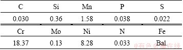
Table 2 Chemical composition of Ti-6Al-4V (mass fraction, %)
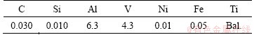
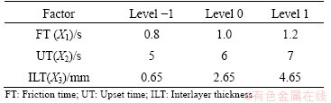
Table 3 Process parameters for friction welding
2.2 Response surface methodology
Response surface methodology is a collection of statistical and mathematical methods that are useful for the modeling and analyzing problems in engineering applications. In this technique, the main aim is to optimize the process parameters through response surface. Response surface methodology also brings out the relationship between the controllable input parameters and the obtained response surfaces.
The procedure of response surface methodology is as follows:
1) Designing of a series of experiments for adequate and reliable measurement of the response of interest;
2) Developing a mathematical model of the second order response surface with the best fittings;
3) Finding the optimal set of experimental parameters that produce the maximum or minimum value of response;
4) Representing the direct and interactive effects of process parameters through two and three dimensional plots.
2.3 Identifying important parameters
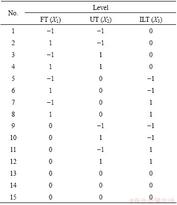
From the literature and basic experiments done in the laboratory [24], predetermined factors for friction welding were chosen. After choosing the factors and levels, the Box-Behnken design was used to perform the experiments as shown in Table 4. The Box-Behnken design is an independent quadratic design in which it does not contain an embedded factorial or fractional factorial design. In this design, the treatment combinations are at the midpoints of the edges of the process space and at the center. These designs are rotatable (or near rotatable) and require 3 levels of each factor.
Table 4 Box-Behnken design
2.4 Conducting experiments and recording responses
After identifying the important friction welding process parameters, experiments were conducted following the Box-Behnken design. The welding was achieved in two phases. Initially, the stainless steel- copper rod joint (Joint 1) was prepared with stainless steel and copper rod by using the levels of parameters like speed 1500 r/min, friction pressure 8 MPa, friction time 2 s, upset pressure 14 MPa and upset time 8 s. Usage of pure copper gives better result for the above combination as shown in Fig. 1. Next, the copper side was cut to 12 mm in length from the joined interface. Then, second phase (Joint 2) of the joint was prepared with titanium alloy and copper side of previous Joint 1, with the parameters used previously. Due to the increased upset pressure and upset time, flash comes out from the copper side as shown in Fig. 2, which results in different thicknesses of copper between Ti alloy and stainless steel. It is considered as interlayer thickness. The process was repeated for different parameters as per Table 4. The samples were subjected to drop test immediately to understand whether the bond is intact. The specimens cleared the drop test without being separated due to excellent bonding, which was achieved using copper as interlayer. Necessary samples were prepared for further evaluation of mechanical and metallurgical properties.
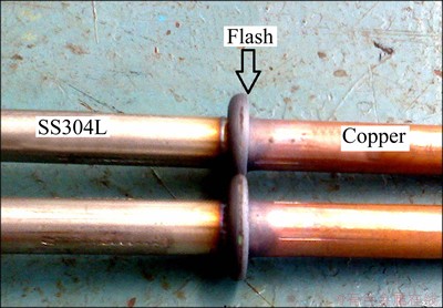
Fig. 1 Friction welded joints (SS304L and copper)
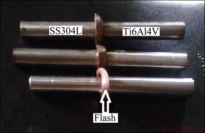
Fig. 2 Friction welded joints (SS304L, copper, Ti-6Al-4V)
2.5 Development of mathematical model and its adequacy checking
Tensile strength=f (FT, UT, ILT)=f(X1, X2, X3)
The second order polynomial (regression) equation used to represent the response tensile strength is given by
Tensile strength=302.3-27.66X1-27.66X2-80.55X3+55.325X1X2+27.66X12+27.66X22+113.087X32
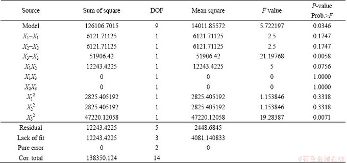
A mathematical model was developed using the second order regression equation. The adequacy of the developed model was checked by using the ANOVA technique. With this technique, if the calculated value of the Fratio of the developed model does not exceed the standard tabulated value of Fratio for a desired confidence level (e.g., 99%), then the model is considered to be adequate within the confidence limit. The ANOVA test results are presented in Table 5 and the model is found to be adequate.
2.6 Optimization procedure using response graphs
During this investigation, an attempt has been made to optimize the friction welding parameters to attain the maximum tensile strength. The developed model given in the equation presented in Section 2.5 was utilized to develop the contour plots and response surfaces. The 3D plot of the model can be viewed to arrive at the optimum values for the process parameters which yield optimum responses considering any two variables at a constant value. The response graphs and contour plots exhibit the behavior of the response (i.e., tensile strength) at different values of the process variables.
Table 5 ANOVA for response surface quadratic model
A contour plot is produced to visually display the optimal process parameter region. For the second-order response surfaces, this plot can be more complex than the simple series of parallel lines that can occur with the first-order models. Once the stationary point is established, it is usually necessary to identify whether the stationary point found is the maximum response, minimum response or saddle point. To sort this, the most straight forward way is to examine it through a contour plot. Contour plots play a very important role in the study of the response surface. By developing contour plots for response surface analysis, the optimum is identified with practical accuracy by characterizing the shape of the surface. If a contour pattern of circular-shaped contours occurs, it tends to suggest independence of the factor effects, while elliptical contours may indicate factor interactions (Montgomery, 1991; Barker, 1985). Response surfaces were developed for all of the models, taking one parameter in the middle level, two parameters in the X and Y axes and the response in the Z axis. The response surfaces clearly indicate the optimal response point.
3 Result and discussion
3.1 Tensile strength
Tensile tests were performed on the samples generated from the joints prepared with constant speed rotation (1500 r/min), constant axial pressure (12 N/mm2) and variable friction time. The prepared specimens are tensile tested as per ASTM standard with a gauge length of 50 mm and a diameter of 12.5 mm (Fig. 3). Tensile test was performed at room temperature on the universal tensile testing machine of MTS criterion series having a capacity of 1000 kN. The test showed that breaking occurs either in the welding area or in the immediate vicinity in the austenitic steel component.
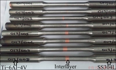
Fig. 3 Samples for tensile test
Earlier studies done on Ti-6Al-4V and X5CrNi18-10 dissimilar friction welded joint without interlayer has produced tensile strength between 340 and 380 MPa [8]. Nickel, vanadium and tantalum were used as an interlayer in friction welding of Grade 1 Ti to 304L SS rods. Tensile strength of Ti/Ta/Ni/SS304L sample produced 388 MPa, Ti/V/Ni/SS304L sample experienced 403 MPa, while Ti/Ni/SS304L sample produced 410 MPa. Further Ti/Ta/SS304L experienced 394 MPa and Ti/V/SS304L produced 388 MPa [14]. When Maraging steel was bonded to low alloy steel with nickel interlayer, tensile strength of 410 MPa was reported [15]. Commercially pure titanium to a 304L stainless steel with an electroplated nickel interlayer has been investigated. Tensile test showed that the maximum average tensile strength of 289 MPa was obtained from the joint welded at a forging pressure of 320 MPa [16]. Ni interlayers were introduced prior to dissimilar friction welding of Ti-6Al-4V base material to three cemented carbide substrates. The tensile strengths of Ti-6Al-4V/ (WC-6%Co) welds were poor and were markedly improved when 20 μm-thick Ni interlayers were introduced prior to dissimilar friction welding [17]. It is also evident from the previous literatures [16,17] that copper has not been used as an interlayer with titanium alloy and SS304L. In TiAl and AISI 4140 steel with copper insert layer revealed that the tensile strength increased with decreasing layer thickness. For a interlayer thickness of 0.6 mm, tensile strength of 250 MPa, for a interlayer thickness of 0.3 mm, 345 MPa and for 0.2 mm, 375 MPa were obtained [18]. The present study with copper interlayer proved that higher tensile strength is achievable. From the experimental interpretation, it is observed that the maximum tensile strength of 523.6 MPa is possible. Response plots are plotted (Fig. 4) to understand the impact of variables on desired output. From the findings, it is observed that the strength gradually reduces with the increase in copper interlayer thickness. One more significant observation is that the bonding of copper between titanium alloy and stainless steel is equally well because of high friction time and upset time of 1.2 and 7 s, respectively (Fig. 4(f)). When friction time and upsetting time are low, the copper de-bonding takes place at titanium alloy side during tensile testing, so it needs more upsetting time for superior bonding.
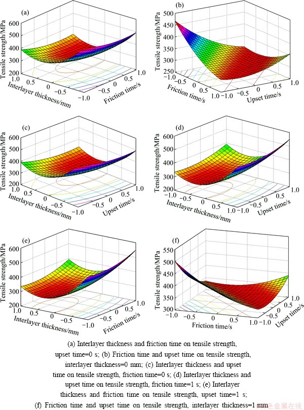
Fig. 4 Response surface graphs depicting effects of process parameters
In the present investigation, SS 304L and titanium alloy with copper as interlayer have been proven to have the highest tensile strength of 523 MPa for an interlayer thickness of 0.65 mm. By increasing the friction time and maintaining constant rotational speed and axial pressure, high quality welded joints without defects are achieved. Response graph in Fig. 4(a) shows the influence of friction time and the interlayer thicknesses on the tensile strength. Both the parameters are found to influence the tensile strength. As the friction time increases, the tensile strength increases and reaches 500 MPa. When the interlayer thickness increases, the tensile strength decreases and reaches 375 MPa. At higher friction time and interlayer thickness, the tensile strength is minimum.
Figure 4(b) shows the influence of friction time and upset time on tensile strength. Both the parameters have an influence on the tensile strength. As the friction time decreases, the tensile strength increases and reaches 450 MPa. When upset time increases, the tensile strength increases and reaches 350 MPa. At lower friction time and upset time, the tensile strength is maximum. At higher upset time and lower friction time, the tensile strength is minimum. Response graph in Fig. 4(c) shows the influence of upset time and interlayer thickness on tensile strength. Both the parameters have an influence on the tensile strength. As the upset time decreases, the tensile strength increases and reaches 500 MPa. When the interlayer thickness increases, the tensile strength decreases and reaches 375 MPa. At higher upset time and interlayer thickness, the tensile strength is minimum.
When friction time is kept at the highest level, the response surface shown in Fig. 4(d) clearly shows that at the highest upset time and lower interlayer thickness, tensile strength more than 500 MPa is achieved. On the contrary, when the interlayer thickness is more and upset time is less, tensile strength above 300 MPa is achieved. Figure 4(e) shows that when upset time is kept at a higher level, at the maximum friction time and minimum interlayer thickness, the maximum tensile strength around 530 MPa is achieved. On the other hand, at higher interlayer thickness and lower friction time, tensile strength of 325 MPa is achieved. Figure 4(f) shows the influence of upset time and friction time on tensile strength when interlayer thickness is maximum. At a lower friction time and lower upset time, the tensile strength rises to 500 MPa for higher level of interlayer thickness.
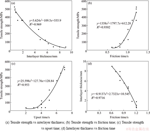
Fig. 5 Plots of process variables
To summarize, as the interlayer thickness decreases, tensile strength increases as shown in Fig. 5(a). When the remaining interlayer metal layer is thick and the insert metal is mixed at the weld interface, the resulting joint strength is low. When the interlayer metal remains thin and is evenly spread over the entire weld interface, joint strength is high. The insert metal was found to prevent direct contact between the base materials. As friction time increases, tensile strength increases as shown in Fig. 5(b). This can be attributed to the amount of heat generated. As the friction time increases, the heat generated increases, which in turn deforms the interlayer to a greater extent and in consequence forms thin interlayer which results in higher tensile strength. Figure 5(c) clearly brings out the effect of upset time. As the upset time increases, the tensile strength increases. The relationship between interlayer thickness and friction time is interesting. As the friction time increases, the interlayer thickness decreases as seen in Fig. 5(d). R2 values depicted in Fig. 5 show that a good correlation exists between actual and predicted values.
3.2 Microstructural characterization
Titanium alloy and stainless steel with copper interlayer shown in Fig. 6 are observed through an metallurgical microscope. The SS matrix far away from the center shows microstructure with equi-axed grains of austenite. The interface zone is not in a straight line and varies according to the upset pressure and also shows the plastic deformation of both the metals. The microstructure of titanium alloy shows the presence of acicular alpha transformed into beta phase and some formation of alpha prime near the centre due to heating and cooling. The microstructure of the copper shows the presence of alpha phase in transformed beta matrix and the interface zone of the copper and stainless steel is visualized as the dark diffusion zone shown in Fig. 6. In the case of Ti alloy and austenitic stainless steel, joints without interlayer produce hard intermetallic layer (Fig. 6).
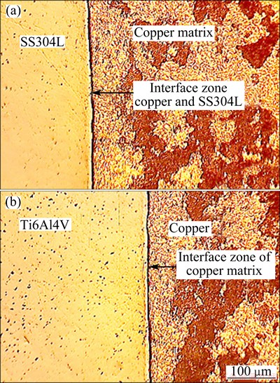
Fig. 6 Metallurgical microscope images of interface zone
From the prepared samples, specimens were subjected to tensile and hardness test to find out suitability of engineering application. Micro hardness testing was done on Vickers hardness test machine model of 423D with 0.098-19.6 N load. In this test, the HV1 method was conducted along the weld centre line at the regular interval of 1 mm. Variation in the hardness near the centre line is due to the present of heat affected zone. From the observed value, it is found that the hardness is increased by 15% to 20% in the stainless steel region and minimum in Ti alloy side. In the case of copper, the hardness is increased by 23%. It is observed that the increase of hardness at the interface of stainless steel and copper may be due to high temperature rise and upset pressure in the weld zone. The microstructure at the stainless steel and copper interface reveals that austenitic structure is changed to martensite due to high upset pressure and rapid atmospheric cooling.
3.3 EDS and XRD analyses
Energy dispersive X-ray (EDS) analysis was performed to find out the elemental distribution at the interface region. The observations were analyzed by 20.00 kV field effect scanning electron microscope coupled with energy dispersive analysis of X-rays (EDS) analysis. EDS of the stainless steel and copper interface region reveals the elemental distribution as seen in Fig. 7. It is evident that 14.52% of mass solubility of copper is seen at the stainless steel region. Also, it is evident that the solubility of copper in the Ti alloy side is more than that of any other elements. The presence of chemical composition at the interface of SS side is enriched with iron (47.97%, mole fraction, the same below), chromium (13.53%) and copper (10.71%). The average composition from the EDS spectrum at the interface shows copper (46.59%) and titanium (21.93%).
From EDS result, it is confirmed that more element copper is diffused on both the sides of the base metal as intermetallic compounds and there is no direct contact between both the parent metals. Such intermetallics region has improved the bonding strength and high tensile strength compared with direct bonding. The binary phase diagram of Cu-Ti indicates the occurrence of various Cu-Ti intermetallic phases with increasing Cu content. The low melting point of copper encourages improved contact area on the mating surface. The nature and the localization of intermetallic phases in these welds were studied by EDS, XRD and micro hardness measurements. The local accumulation of Cu3-Ti and Fe30CuMn30 based phase is less detrimental to the strength of the welds, which makes high strength joint possible (Fig. 8).
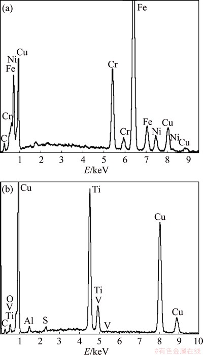
Fig. 7 EDS patters at SS-copper (a) and Ti alloy-copper (b) interfaces
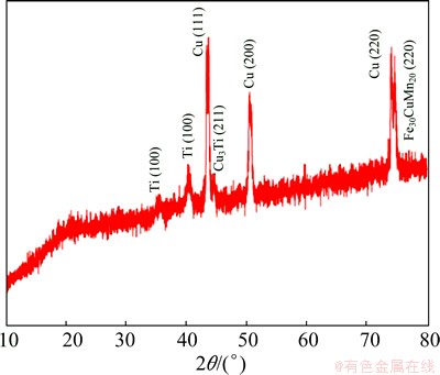
Fig. 8 XRD pattern of intermetallics in weld zone
4 Conclusions
1) An empirical relationship was developed to predict the tensile strength of friction welded Ti alloy and stainless steel joint at 95% confident level.
2) The maximum tensile strength of 523 MPa could be attained with the welding parameters of spindle speed 1500 r/min, friction pressure 12 N/mm2, upset pressure 40 N/mm2, friction time 1.2 s and upset time 7 s.
3) In mechanical and metallurgical characterizations, it is observed that, samples with an optimum parameter with low interlayer thickness produce better results.
4) The presence of copper interlayer in this joint plays a significant role in obtaining excellent bonding between Ti alloy and stainless steel without crack and preventing major martensitic changes in the HAZ.
5) In copper interlayer, the heat affected zone is narrow and equally distributes on both the sides of the parent metal due to the minimum change of microstructure in the base metal.
6) The formation of intermetallic compounds namely Cu3Ti in Ti alloy side and Fe30CuMn20 in SS side reduces the effect of brittle intermetallics on the mechanical properties.
References
[1] COSMIN GROZA A, ION MITELEA A, MARCELA ELENA D. Mechanical and structural characteristics of friction welded TI-6Al-4V+X5CRNI18-10 dissimilar joints [J]. Metal, 2011, 5: 18-20.
[2] SHAMANIAN M, SALEHI M, SAATCHI A, NORTH T H. Influence of Ni interlayers on the mechanical properties of Ti6Al4V/ (WC-Co) friction weld [J]. Materials and Manufacturing Processes, 2003, 18: 581-598.
[3] SATHIYA P, ARAVINDAN S, NOORUL H, PANNEERSELVAM A K. Optimization of welding parameters using simulated annealing [J]. Indian Journal of Engineering and Material Sciences, 2006, 13: 37-44.
[4] BALASUBRAMANIAN M, JAYABALAN V, BALASUBRAMANIAN V. Optimizing the pulsed current GTAW parameters to attain maximum impact toughness [J]. Materials and Manufacturing Processes, 2008, 23: 69-73.
[5] PAVENTHAN P, LAKSHMINARAYANAN R, BALASUBRAMANIAN V. Prediction and optimization of friction welding parameters for joining aluminium alloy and stainless steel [J]. Transactions of Nonferrous Metals Society of China, 2011, 21(7): 1480-1485.
[6] SELVAKUMAR S T, PALANIKUMAR K, UMANATH K, JAYAPERUMAL D. Analysis of friction welding parameters on mechanical, metallurgical and chemical properties of AISI 1035 steel joints [J]. Journal of Materials and Design, 2015, 65:652-661.
[7] DEEPAK KUMAR M, VENKATAKRISHNAN P G. Optimization on friction welding of aluminum alloy 6082 T6 and austenitic stainless steel 304 [J]. International Journal of Engineering Development and Research, 2014, 2: 522-527.
[8] LESNIEWSKI J, AMBROZIAK A. Modelling the friction welding of titanium and tungsten pseudoalloy [J]. Archives of Civil and Mechanical Engineering, 2014, 3: 229-233.
[9] AVINASH S, PACHAL, AMOLBAGESAR. Taguchi optimization of process parameter in friction welding of 6061 aluminum alloy and 304 steel [J]. International Journal of Engineering Technology and Advanced Engineering, 2013, 4(1): 2250-2459.
[10] PASUPATHY J, RAVISANKAR V. Parametric optimization of TIG welding parameters using Taguchi method for dissimilar joint [J]. Scientific & Engineering Research, 2013, 4: 25-28.
[11] SHANJEEVI C, SATISHKUMAR S, SATHIYA P. Evaluation of mechanical and metallurgical properties of dissimilar materials by friction welding [J]. Procedia Engineering, 2013, 64: 1514-1523.
[12] MASAAKI K, YOSHITAKA S, MASAHIRO K, KOICHI K, AKIYOSHI F. Effect of friction welding condition and weld faying surface properties on tensile strength of friction welded joint between pure titanium and pure copper [J]. JSMME, 2011, 12: 849-865.
[13] LEE W B, KIM Y J, JUNG S B. Effects of copper insert layer on the properties of friction welded joints between TiAl and AISI 4140 structural steel [J]. Intermetallic, 2004, 12: 671-678.
[14] ASHFAQ M, PRASAD RAO K, KHALID RAFI H, MURTY B S, DEY H C, BHADURI A K. Friction welding of titanium to 304L stainless steel using interlayer [J]. Practical Metallography, 2011, 48(4): 188-207.
[15] MADHUSUDHAN REDDY G, VENKATARAMANA P. Role of nickel as an interlayer in dissimilar metal friction welding of maraging steel to low alloy steel [J]. Journal of Materials Processing Technology, 2012, 212: 66-77.
[16] MURALIMOHAN C H, MUTHUPANDI V, SIVAPRASAD K. Properties of friction welding titanium-stainless steel joint with a nickel interlayer [J]. Procedia Materials Science, 2014, 5: 1120-1129.
[17] SHAMANIAN M, SALEHI M, SAATCHI A, NORTH T H. Influence of Ni interlayer on the mechanical properties of Ti6Al4V/ (WC-Co) friction weld [J]. Materials and Manufacturing Processes 2003, 18: 581-598.
[18] MADHUSUDHAN REDDY G, MOHANDAS T, SAMBASIVARAO A, SATYANARAYANA V V. Influence of welding processes on microstructure and mechanical properties of dissimilar austenitic- ferrite stainless steel welds [J]. Materials and Manufacturing Processes, 2005, 20(2): 147-173.
[19] SASSANI F, NEELAM J R. Friction welding of incompatible materials [J]. Welding Research Supplement, 1988, 1: 264s-270s.
[20]  K. Friction welding of ductile iron with stainless steel [J]. Journal of Materials Processing Technology, 2013, 213: 453-462.
[21] BOX G E P, HUNTER W G, HUNTER J S. Statistics for experimenters [M]. New York: Wiley, 1978.
[22] BOX G E P, BENHKEN D W. Some new three level designs for the study of quantitative variables [J]. Technometrics, 1960, 2: 455-475.
[23] MONTGOMERY C D. Design and analysis of experiments [M]. Singapore: John Wiley and Sons, Pte. Ltd, 2001.
[24] KUMAR R, BALASUBRAMANIAN M. Experimental investigation of Ti-6Al-4V titanium alloy and stainless steel 304L friction welded with copper interlayer [J]. Defence Technology, 2015, 11: 67-75.
R. KUMAR1, M. BALASUBRAMANIAN2
1. Department of Mechanical Engineering, SKP Institute of Technology, Tiruvannamalai, Tamilnadu 606611, India;
2. RMK College of Engineering and Technology, Tiruvallur, Tamilnadu 601206, India
摘 要:提出了摩擦焊接过程中近优化设置工艺参数。基于不同的输入参数,如摩擦压力、摩擦时间、顶锻压力和顶锻时间及输出参数,如拉伸强度、硬度和材料损耗,成功获得摩擦焊接工艺。采用夹层技术,通过摩擦焊接工艺,连接Ti-6Al-4V和SS304L。采用响应曲面法和Box-Behnken设计确定实验次数并证实优化工艺参数,以得到更好的接头强度。结果很令人满意。在摩擦压力为12 N/mm2、顶锻压力为40 N/mm2、摩擦时间为1.2 s、定锻时间为7 s的条件下,得到接头强度为523 MPa。
关键词:摩擦焊接;焊接参数;Ti-6Al-4V;SS304L;铜夹层
(Edited by Xiang-qun LI)
Corresponding author: M. BALASUBRAMANIAN; Tel: +91-9841714830; Fax: +91-4433303636; E-mail: manianmb@gmail.com
DOI: 10.1016/S1003-6326(15)63959-0

