装甲级Al-Zn-Mg合金搅拌摩擦焊接接头的力学性能
来源期刊:中国有色金属学报(英文版)2017年第3期
论文作者:C. SHARMA V. UPADHYAY D. K. DWIVEDI P. KUMAR
文章页码:493 - 506
关键词:搅拌摩擦焊;焊接参数;力学性能;断裂形貌;回归模型
Key words:friction stir welding; welding parameters; mechanical properties; fractography; regression modeling
摘 要:研究焊接速度和旋转速度对装甲级铝合金搅拌摩擦焊接接头的形成和力学性能的影响。采用弯曲试验、显微硬度测试、力学性能测试、光学显微镜和扫描电子显微镜对焊接接头进行表征。焊接接头的力学性能(包括显微硬度、抗拉强度和伸长率)随旋转速度增加而增加,随焊接速度减小而增加。焊接速度对热影响区显微硬度的影响比旋转速度更强。焊接速度和旋转速度对搅拌摩擦焊接接头的力学性能有重要影响,且其影响可用回归模型进行预测。
Abstract: The influence of different welding speeds and rotary speeds on the formation and mechanical properties of friction stir weld joints of armor grade aluminum alloy was presented. The developed weld joints were characterized by bend tests, micro-hardness tests, tensile tests, optical and scanning electron microscopies. Mechanical properties (i.e., micro-hardness, ultimate tensile strength and elongation to fracture) increased with the increase in rotary speed or decrease in welding speed. The effect of welding speed on micro-hardness of heat affected zones was more profound than the rotary speeds. The welding speeds and rotary speeds influenced the mechanical properties and their effects on various mechanical properties of the friction stir welded joints can be predicted with the help of regression models.
Trans. Nonferrous Met. Soc. China 27(2017) 493-506
C. SHARMA1, V. UPADHYAY2, D. K. DWIVEDI3, P. KUMAR3
1. Rustamji Institute of Technology, BSF Academy, Tekanpur, Gwalior, Madhyapradesh 475005, India;
2. Mechanical Engineering Department, National Institute of Technology Patna, Patna 800005, India;
3. Mechanical and Industrial Engineering Department, I.I.T. Roorkee, Uttarkhand 247667, India
Received 21 January 2016; accepted 17 November 2016
Abstract: The influence of different welding speeds and rotary speeds on the formation and mechanical properties of friction stir weld joints of armor grade aluminum alloy was presented. The developed weld joints were characterized by bend tests, micro-hardness tests, tensile tests, optical and scanning electron microscopies. Mechanical properties (i.e., micro-hardness, ultimate tensile strength and elongation to fracture) increased with the increase in rotary speed or decrease in welding speed. The effect of welding speed on micro-hardness of heat affected zones was more profound than the rotary speeds. The welding speeds and rotary speeds influenced the mechanical properties and their effects on various mechanical properties of the friction stir welded joints can be predicted with the help of regression models.
Key words: friction stir welding; welding parameters; mechanical properties; fractography; regression modeling
1 Introduction
In the present competitive era, the use of aluminum alloys for the manufacturing of armored fighting vehicles is rapidly increasing as armored fighting vehicle needs to be deployed rapidly and move swiftly. Aluminum alloys are lighter and offer high specific strength and superior ballistic piercing strength when compared to steels. The ability of heat treatable aluminum alloys (7039, 7085, etc.) to gain strength by natural aging promoted their use over non heat treatable aluminum alloys of 5xxx series (e.g., 5083) [1]. Fusion welded hulls of 7xxx series aluminum alloys are prone to stress corrosion cracking in heat affected zone [2,3]. Moreover, high residual stresses arising from multipass welding of thick plates further provoke problem of stress corrosion cracking.
Friction stir welding (FSW) is maturing as solid state joining technique, originally developed to join difficult to fusion weld aluminum alloys. In FSW, material is subjected to plastic deformation and friction by a rotating and traversing profiled tool to soften the material. The flowing material is consolidated into a monolithic joint due to combined effect of forging and extrusion. The joining is accomplished at peak temperature that is lower than the melting temperature, therefore, FSW eliminates most of the problems encountered in fusion welding of aluminum alloys [4-6].
A detailed literature review on the welding of Al-Zn-Mg alloy 7039, which is a precipitation hardening armor grade aluminum alloy, was carried out. GHOSH et al [7] performed MIG welding and reported that pulse parameters affect shape of weld joint, microstructure and mechanical properties while GHOSH and SHARMA [8] found that use of pulse current increases magnesium loss and decreases zinc loss. The yield strength, ductility and hardness of the 7039 aluminum alloy plays a major role in deciding weld quality of friction stir welded joints [9]. Friction stir welding of Al-Zn-Mg alloy AA7039 is recommended to be performed in W temper condition because of better tensile properties and superior fatigue strength [10]. The pin diameter, tool shoulder geometry and concavity of the shoulder surface affect the weld tensile strength and weld cross-sectional area of friction stir welds. Pin diameter dominates others parameters in controlling FSW characteristics as it mainly governs stirring of deformed and plasticized material in the weld region [11]. FSW joints were heterogeneous as different layers of joint exhibit significant heterogeneity in respect of microstructure and mechanical properties. Top layer of joint was the strongest while middle layer is the weakest [12]. Various in-process cooling techniques were also employed during FSW and water cooling was more effective than in-process cooling with compressed air and liquid nitrogen. In-process cooling during FSW is beneficial as it yields stronger and smaller heat affected zone(s) owing to reduced extent of coarsening. Moreover, in-process cooling shifts the fracture location from heat affected zone (HAZ) to weld nugget zone (WNZ) [13].
Literature review reveals the scarcity of research on the modeling of mechanical properties of the armor grade Al-Zn-Mg alloy. It is worth mentioning that the study of mechanical properties is a labor incentive and time consuming process as it requires sample preparation, mounting, testing, etc., to determine their respective values. So, for quick determination of their values, regression model can be developed which in-turn is based on some experimental values properly distributed in design space. Therefore, the objective of this research is two folds, i.e., to develop regression models of various mechanical properties and then to investigate the influence of varying rotary speed and traverse speed on the characteristics of FSW joints by means of developed regression models.
2 Experimental
2.1 Base metal
The armor grade Al-Zn-Mg 7039 alloy in peak hardened T6 temper was used as base metal in this work. The base metal comprises 4.69% Zn, 2.37% Mg, 0.68% Mn, 0.69% Fe, 0.31% Si, 0.05% Cu, and remaining aluminum. Figure 1 shows electron dispersive X-ray (EDAX) analysis of the base metal. At room temperature, the ultimate tensile strength, yield strength, elongation to fracture and micro-hardness of base metal were 414 MPa, 328 MPa, 15.1% and HV 135, respectively.

Fig. 1 Electron dispersive X-ray (EDAX) analysis showing chemical composition of base metal
The 5 mm thick extruded sheets were cut in plates of 300 mm in length and 50 mm in width. Surfaces of these plates were then cleaned to remove natural oxide layer and other foreign particles from the faying surfaces. The plates were arranged in square butt joint configuration and were held firmly in position, without any gap between faying surfaces of the plates using specially fabricated fixture.
2.2 Machine tool and FSW tool
FSW was performed parallel to plate extrusion direction in single pass using modified vertical milling machine (HMT India, 5 kW). The tools were made of die steel and had flat shoulder with straight cylindrical and truncated conical threaded pins. The pin length and depth of shoulder plunge were 4.7 mm and 0.2 mm for both the tools. Tool pins had anticlockwise threads of 1 mm pitch to facilitate the downward flow of plasticized material beneath the shoulder. A constant tool tilt of 2.5° from the vertical axis was used to facilitate the consolidation of plasticized material.
2.3 Selection of welding parameters
The welding conditions for pilot tests were selected based on the review of literature and machine constraints. Initially many pilot experiments were performed using welding speed and rotary speed in the range of 8-190 mm/min and 300-635 r/min to develop FSW joints with tool having flat shoulder of 18 mm in diameter and straight cylindrical threaded pin of 7 mm in diameter. The use of such a tool resulted in defective FSW joints mainly due to the occurrence of excessive flash, unfilled section and the tunnel defects as shown in Fig. 2.

Fig. 2 Effect of improper FSW parameters on quality of FSW joints
In order to develop sound FSW joints, tool was redesigned having truncated conical pin and smaller shoulder and pin diameter. The use of smaller shoulder diameter and pin diameter resulted in decreased heat input to the weld which in turn minimized formation of defects owing to smooth flow (i.e., absence of turbulence) of plasticized material. FSW joints developed with low welding speed have excessive flash while those developed with lower rotary speed resulted in lack of fill and incomplete penetration at the root.
Finally, based on the findings of many trial and error experiments, range of process parameters and tool dimensions (which resulted in sound FSW joints) was selected for final experiments as listed in Table 1.
The tool geometry was kept fixed during experimentation and welding parameters were varied to develop FSW joints by one factor at a time approach.
2.4 Mechanical testing
The soundness of the weld joints was checked by three point face and root bend test as per ASTM E290-09 guideline using 100 mm-long and 20 mm-wide specimens [14]. Mechanical properties of base metal and friction stir welded joints were determined by tensile and microhardness tests in ambient condition. Due to size limitations, sub size flat tensile specimens of 100 mm in overall length and 10 mm in width at ends were prepared from base metal and friction stir welded joints as per ASTM E8M-09 guidelines [15]. The central region of tensile specimens had a gauge length of 20 mm and width of 6 mm and consists all the zones of FSW welds. Computerized universal testing machine of 25 kN load capacity (H25K-S, Hounsfield, UK) was used for conducting tensile and bend tests at a cross head speed of 1 mm/min at room temperature. The machine was equipped with Q Mat software (Version 5.35) to record load and extension data during test so as to perform post-test analysis. Three tensile tests were performed in each condition and average values were used for analysis and discussion throughout this work. The ultimate tensile strength (UTS) and strain, elongation to fracture (EL) were determined for each test. Variation of micro-hardness across the FSW joints was recorded by Vickers micro-hardness tester (VHM-002V Walter UHL, Germany) at a load of 100 g and dwell time of 30 s.
2.5 Microstructural characterization
Samples for microstructural investigation were prepared by following standard metallographic techniques which include mounting, polishing and etching. Polished samples were etched for 90 s in Keller’s reagent (2 mL nitric acid, 4 mL hydrofluoric acid and 94 mL water) for macrostructural and microstructural analyses. Microstructural investigation of friction stir welded joints and base metal was carried out with an optical microscope (Leica DMI500 M, Germany) and field emission scanning electron microscope (FE-SEM) (FEI-Quanta 200 ). Image analysis of weld micrographs was done using Image J 1.37v, image analyzing software to determine average size of α aluminum grains present in different zones of FSW joints and base metal using linear intercept method in accordance to ASTM E112-10 guidelines [16].
2.6 Multiple regression modeling
Multiple regression modeling is widely used by scientists and engineers to develop regression models due to its inherent simplicity. It is also used in this work as it is a quiet accurate statistical technique to determine the relationship between the response variable and the input parameters (regressors). Since it is a well-known technique, only formulation is given in this work for the sake of completeness.
Multiple regression is a linear regression model that can explain the relationship between response and regressors, which can be presented as
y=β0+β1x1+β2x2+ε (1)
where y represents the response, β0, β1 and β2 represent the regression coefficients, x1 and x2 are regressors (Welding speed (WS) and rotary speed (RS), respectively) and ε is error.
A second order model in terms of two variables is expressed as
y=β0+β1x1+β2x2+ +
+ +β5x1x2+ε (2)
Now this second order model can be converted in linear regression model by considering  ,
,  , x5=x1x2. So, the above model becomes
y=β0+β1x1+β2x2+β3x3+β4x4+β5x5+ε (3)
This is a linear regression model and thus the usual model fitting can be carried out to determine the regression coefficients [17].
The R2 statistics is determined and most accurate models thus obtained were used for prediction purpose. The detailed statistical analysis is not presented in the work to focus on the core investigations.
Table 1 Parameters used for friction stir welding

3 Results
3.1 Weld quality testing
FSW joints were inspected visually for voids, cracks, and other surface defects. FSW joints free from surface defects were then subjected to three-point face and root bend test to reveal the presence of subsurface defects. If a crack appears at the external surface during bending then these flawed weld joints were discarded. The surfaces of some FSW joints after face and root bend tests are shown in Fig. 3.

Fig. 3 Photographs of FSW joints developed using different welding parameters subjected to face bend (a) and root bend test (b)
All the FSW joints passed the face bend tests successfully while those developed using high welding speed of 190 mm/min and low rotary speed of 410 r/min and 540 r/min fail in root bend test. Crack was observed on external surfaces of these joints subjected to bending as shown in Fig. 3.
3.2 Microstructure
FSW transformed the initial microstructure of the base metal and resulted in the formation of WNZ, thermo-mechanically affected zone (TMAZ) and HAZ in the base metal as evident from the micrograph shown in Fig. 4. These zones are characteristic of FSW process. The transition from WNZ to TMAZ is clearly
distinguishable on advancing side while that on retreating side is gradual (Fig. 4).

Fig. 4 Macrograph showing evolution of different zones in friction stir welded joint
Figure 5 shows the enlarged micrographs showing the evolution of microstructure in different zones of FSW joints, i.e., WNZ, TMAZs and HAZs. Average sizes of α aluminum grains present in different zones of friction stir welded joints are shown in Table 2. The FSW completely changed the microstructure of the base metal which had unrecrystallized coarser α aluminum grain of 44.3 μm average size with uniformly distributed η(MgZn2) precipitates.
The unrecrystallized coarser α aluminum grains present in the base metal were dynamically recrystallized in WNZ, deformed in TMAZ and coarsened in HAZ of FSW joints (Figs. 5(a)-(f)). Figure 6 shows the micrograph of the center of weld nugget zone for some typical values of welding and rotary speed. All the WNZs invariably show fine recrystallized equiaxed grain structure with few tiny η second phase strengthening precipitates as compared to base metal. It is evident that size of α aluminum grains present in WNZs decreases with increasing welding speed (Figs. 6(a)-(c)) but increases with increasing rotary speed (Figs. 6(d)-(f)). Next to WNZ is TMAZ which shows highly deformed bent and flattened inhomogeneous α aluminum grains (Fig. 5). The average width of elongated bent α aluminum grains in TMAZ was 35.3-66.1 μm on advancing side while on retreating side it was 28.3-63.2 μm. Average width of α aluminum grains first increases then decreases with increase in welding speed and opposite trend was observed with increase in rotary speed.
Table 2 Variation of α aluminum grains size in different zones of FSW joint with welding parameters


Fig. 5 Effect of welding parameters on evolution of microstructures in different zones of FSW joints developed using constant rotary speed of 635 r/min and varying welding speeds of 75 mm/min (a), 120 mm/min (b), 190 mm/min (c); and constant welding speed of 75 mm/min and varying rotary speeds of 410 r/min (d), 540 r/min (e) and 635 r/min (f), respectively
Recrystallization was not observed in TMAZs irrespective of the used combination of process parameters. In HAZ, average size of α aluminum grains is larger than that of base metal (Fig. 7). HAZ is influenced by frictional heat only and not by mechanical deformation. The grains in HAZs were found to be coarser on advancing side (57.9-122.1 μm) than retreating side (41.5-77.3 μm). It was observed that size of α aluminum grains present in HAZs increases with increase in welding speed and the same was found to decrease with increase in rotary speed. The trend of variation of grain size in HAZs with welding parameters was found opposite to that in WNZs.
High magnification micrographs of WNZ, TMAZ, HAZ and base metal are shown in Fig. 7 to investigate the morphology of strengthening precipitates. FSW joints (2, 3, 4 and 5) developed using high welding speed (120 and 190 mm/min) and low rotary speed (410 and 540 r/min) exhibit somewhat more and larger second phase η strengthening precipitates in WNZs and TMAZs than those using low welding speed (75 mm/min) and high rotary speed (635 r/min). FSW joints developed using low welding speed of 75 mm/min and high rotary speed of 635 r/min exhibit finer second phase η strengthening precipitates than those developed using high welding speed (120 and 190 mm/min) and low rotary speed (410 and 540 r/min). Further, second phase η strengthening precipitates in TMAZs and HAZs were found coarser on advancing side than on retreating side.
3.3 Mechanical properties
Tensile properties of FSW joints were determined by performing tensile tests on transverse tensile specimens which were prepared by keeping the weld nugget zone at their center. Tensile properties of FSW joints under various combinations of welding parameters are presented in Table 3.
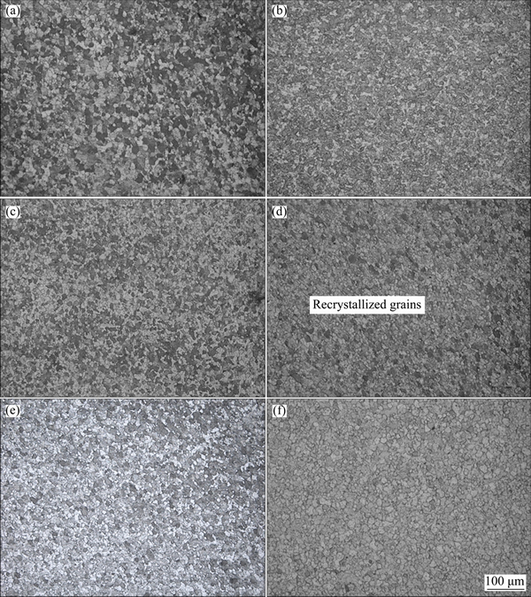
Fig. 6 Effect of welding parameters on evolution of microstructures in weld nugget zone of FSW joints developed using constant rotary speed of 635 r/min and varying welding speeds of 75 mm/min (a), 120 mm/min (b), 190 mm/min (c); and constant welding speed of 75 mm/min and varying rotary speeds of (d) 410 r/min, (e) 540 r/min and (f) 635 r/min, respectively
The experimental values presented in Table 3 were used to develop regression models for ultimate tensile strength, elongation and joint efficiency. The first order and second order model were developed for each response and R2 statistics of both models were compared. Based on the R2 statistics of regression equation, most accurate model was identified for prediction of each mechanical property. Highlighted model in Table 4 represents the selected model. Selected models were then used to study the trend and variation by plotting the graphs of the respective response parameters.
The variation of ultimate tensile strength with welding speed at different constant rotary speed is presented in Fig. 8 wherefrom it is evident that with the increase in welding speed the tensile strength decreases at all rotary speeds. The effect of welding speed on ultimate tensile strength is comparatively small at lower rotating speed (410 r/min). However, at higher rotary speed (635 r/min), effect of welding speed is more drastic, and it reduces significantly.
On the other hand, trend of variation of ultimate tensile strength with increase in rotary speed at different constant welding speeds is opposite to that of welding speed (Fig. 8). A sharp increase in ultimate tensile strength was observed with increase in rotary speed from 410 to 540 r/min but with further increase in welding speed to 635 r/min, the improvement is comparatively less. The increase of 140 r/min beyond 410 r/min at 75 m/min resulted in 65 MPa increase in UTS whereas an increase of 95 r/min beyond 540 r/min resulted only 18 MPa increase in UTS. This implies that the effect of rotary speed on ultimate tensile strength was diminished beyond 540 r/min.

Fig. 7 Effect of welding parameters on morphologies of strengthening precipitates (75 mm/min and 635 r/min) in different zones
Table 3 Tensile properties of friction stir welded joints

The variation of elongation with welding speed at different rotary speeds is presented in Fig. 9 wherefrom it is evident that the elongation reduces with increase in welding speed whereas it improves with increase in rotary speed.
The effect of change in welding speed from 75 to 120 mm/min on elongation was not as much severe as from 120 to 190 mm/min. The increase in rotary speed at constant welding speed increased the elongation. The extent of increase in elongation with increase in rotary speed is more at lower welding speed than at higher welding speed.
The joint efficiency of FSW joints, which is the ratio of ultimate tensile strength of welded joint to that of base metal, decreases linearly with increase in welding speed at all rotary speeds while increase in rotary speed at all welding speed increases joints efficiency as is evident from Fig. 10. The joint efficiency was found more sensitive to change with rotary speed as compared to welding speed.
The microhardness of the weld joints was measured in WNZs and HAZs on transverse plane to study their variation with varying welding parameters and are presented in Table 5.
Table 4 Regression models of UTS, elongation and joint efficiency with associated R2 statistics
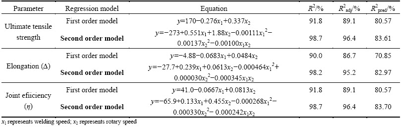
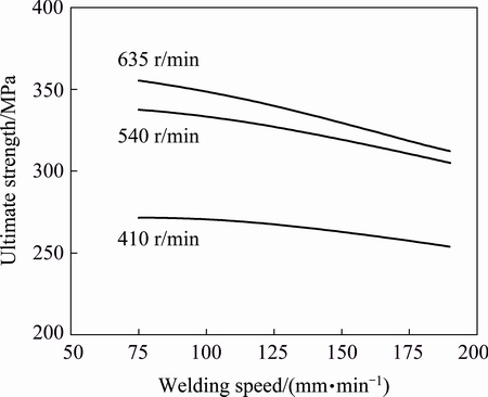
Fig. 8 Variation of ultimate tensile strength with welding speed at different rotary speeds

Fig. 9 Variation of elongation with welding speed at different rotary speeds
With the help of the experimental values presented in Table 5, regression models for microhardness in WNZs and HAZs were developed and are presented in Table 6. On the basis of R2 statistics, most accurate models were identified for prediction of microhardness in WNZ and HAZ. These selected models were then used to study the trend and variation of the respective response parameters and are presented in Figs. 11 and 12.
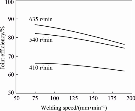
Fig. 10 Variation of joint efficiency with welding speed at different rotary speeds
Table 5 Microhardness in weld nugget zone and heat affected zone with varying welding parameters

The average values of microhardness of all the weld joints irrespective of welding parameters, were found lower than that of the base metal. It is evident from Fig. 11 that microhardness of WNZ decreases with the increase in welding speed but increases with the increase in rotary speed. The effect of welding speed is marginal at low rotary speed. However, at higher rotary speed, WNZ microhardness promptly decreases with the increase in welding speed from 75 to 190 mm/min. Contradictory to previous trend, an increasing trend of hardness was observed with the increase in rotary speed at different constant welding speeds. The extent of increase in microhardness of WNZs was found more with increase in rotary speed from 410 to 635 r/min at lower welding speed than at higher welding speed. These results are also in close agreement with the findings of tensile properties and weld nugget grain size.
Table 6 Regression models for microhardness in weld nugget zone and heat affected zone and associated R2 statistics


Fig. 11 Variation of weld nugget zone microhardness with welding speed at different rotary speeds

Fig. 12 Variation of heat affected zone microhardness with welding speed at different rotary speeds
The influences of rotary speed and welding speed on the microhardness of HAZs of FSW joints are presented in Fig. 12. The effect of rotary speed and welding speed on the microhardness of heat affected zones of FSW joints is found to follow opposite trend to that of WNZ microhardness. The effect of welding speed on microhardness of HAZs was more profound than the rotary speed.
3.4 Fractography
Welding parameters significantly influence fracture behavior of FSW joints as evident from macro and micro fractographs of broken tensile specimen of FSW joints shown in Figs. 13 and 14, respectively. From the macro fractographs, it is evident that fracture surfaces of joints 1, 2 and 6 are flat, fibrous and inclined at 45° to loading axis. Further, presence of white slant area on these joints suggests that these joints underwent considerable necking at the point of plastic instability where strain hardening fails to compensate reduction in cross-sectional area before failure (Figs. 13(a), (b) and (f)). The fracture surfaces of other joints (3, 4 and 5) were wavy and perpendicular to loading axis and there was no necking in failure zone. The joint 4 exhibited large region on the root side of joint where material is poorly consolidated and metallurgical bonding is weak.
Fracture surfaces of joints 1, 2, 5 and 6 were covered with cup like depression, i.e., dimples of different sizes and shapes suggesting a ductile fracture mode for these joints. Joints 1 and 6 had large diameter dimples than joints 2 and 5. The joint 5 had least population of dimples with fewer sheared dimples. In some of the broken dimples, coarsened second phase strengthening η' precipitates are visible, indicating that fracture of these hard and brittle precipitates initiated the formation of microvoids. These microvoids grow and coalesce into large crack due to continued tensioning which then grow transverse to longitudinal axis until final fracture occurs.
In the case of joints 3 and 4, fracture surfaces were relatively featureless and did not show dimples, cleavage or river pattern. However, there are clear sign of weak metallurgical bonding of plasticized flowing material beneath the tool shoulder at the root of weld joints. At high welding speed or low rotary speed, low heat input per unit length of weld retards the flowability of material and sluggish flow of deformed material leads to poor consolidation by rotating and traversing tool. The presence of large parallel crack/voids on fracture surface of joint 4 may be attributed to above mentioned factors.

Fig. 13 Macro fractographs showing effect of welding parameters on fracture behavior of FSW joints developed using constant rotary speed of 635 r/min and varying welding speeds of 75 mm/min (a), 120 mm/min (b), 190 mm/min (c), and constant welding speed of 75 mm/min and varying rotary speeds of 410 r/min (d), 540 r/min (e) and 635 r/min (f), respectively
4 Discussion
Welding parameters influence material flow and temperature distribution across the weld which in turn affect characteristics of FSW joints. Rotary speed determines the amount of heat produced per unit time along with stirring and mixing of workpiece material around the pin. Welding speed or tool traverse speed govern the weld thermal cycle, i.e., maximum temperature generated during welding and the time the material subjected to high temperature during welding [18]. The increase in rotary speed at constant welding speed and decrease in welding speed at constant rotary speed increase generation of heat which in turn increases the softening and improves flowability of the deformed material beneath the tool shoulder. WNZs of all the FSW joints invariably have fine and recrystallized equiaxed grains (Fig. 6) because severe plastic deformation and frictional heating generated temperature high enough to cause dynamic recrystallization [19-21]. Thus, the coarse grain structure of base metal transformed into fine and equiaxed grain structure in WNZs. In comparison to base metal, fewer second phase η strengthening precipitates were observed in WNZs as they are broken down and uniformly distributed by stirring tool. It was observed that size of α aluminum grains present in WNZs decreases with increasing welding speed and the same trend was observed with decreasing rotary speed (Fig. 6). The degree of plastic deformation and frictional heating increase with increase in rotary speed and decrease in welding speed. An increase in welding speed at constant rotary speed and decrease in rotary speed at constant welding speed of the tool in fact decrease the net heat input per unit length being provided for developing weld joint. The reduction in heat input results in low peak temperature, short soaking period above recrystallization temperature and high cooling rates after FSW. Dynamic recrystallization results in the development of fine equiaxed grains [19-21] after nucleation experience static grain growth during the remaining thermal cycle of FSW process [22,23]. The static grain growth increases size of α aluminum grain in WNZ. At low welding speed and high rotary speed, the peak annealing temperature is high for longer soaking period which in turn leads to prolonged static grain growth. This prolonged static grain growth is responsible for coarser α aluminum grains in WNZs of friction stir welded joints developed using low welding speed of 75 mm/min and high rotary speed of 635 r/min than other joints. The WNZ is surrounded by TMAZ that has highly deformed and bent inhomogeneous aluminum grains due to stirring action produced by rotating tool. The dynamic recrystallization is not observed in TMAZs (Fig. 5) due to lower amount of frictional heating and plastic deformation [19]. High stacking fault energy of aluminum alloys acts as barrier to cause dynamic recrystallization in TMAZs. The elongated bent α aluminum grains and second phase η strengthening precipitates in thermo mechanically zone were found coarser on advancing side than retreating side primarily due to the fact that more heat is generated on advancing side (due to higher relative velocity of tool) than that on retreating side.
Average size of α aluminum grains in HAZs of friction stir welded joints was larger than base metal (Figs. 5 and 7). HAZ is influenced by frictional heat only and not by mechanical deformation. The average size of α aluminum grains increases with increase in welding speed while increase in rotary speed decreases average size of α aluminum grains. Analysis of these results suggests that welding speed has more dominating role in controlling grain size in HAZs than rotary speed. It is felt that the extent of reversion of hardening precipitates directly affects the coarsening of aluminum grains due to their pinning effect on grain boundary movement. Therefore, increase in dissolution of strengthening precipitates results in greater coarsening of aluminum grains in HAZs [13]. High welding speed or low rotary speed reduces the heat input as well as maximum temperature experienced in HAZs. However, temperature (250-350 °C) attained in HAZs is enough to cause dissolution of fine secondary precipitates [20,22,24]. The dissolution of fine η strengthening precipitates in turn promotes coarsening of α aluminum grains owing to loss of pinning effect on grain boundary movement by hardening precipitates.

Fig. 14 Micro fractographs showing effect of welding parameters on fracture behavior of FSW joints developed using constant rotary speed of 635 r/min and varying welding speed of 75 mm/min (a), 120 mm/min (b), 190 mm/min (c), and constant welding speed of 75 mm/min and varying rotary speed of 410 r/min (d), 540 r/min (e) and 635 r/min (f), respectively
The average microhardness of the WNZs was found to be lower than the base metal (HV 135). The average microhardness in the WNZs decreased from HV 115.3 to 106.2 with increase in welding speed from 75 to 190 mm/min (Fig. 11), while the average microhardness of the weld nugget increased from HV 101.9 to 115.3 with increase in rotary speed from 410 to 635 r/min (Fig. 11). Microhardness results are not in agreement with α aluminum grain size as the same is also greatly affected by the distribution of strengthening precipitates (size, shape and volume) in case of precipitation hardening aluminum alloys [25]. WNZ experiences higher peak temperature (420-480 °C) for longer duration, dissolves most of the η' precipitates leaving behind few coarser η precipitates which in turn increases solute concentration available for re-precipitation on account of natural aging. Thus, higher microhardness of WNZ can be attributed to better post-weld natural aging owing to increased solute concentration with decrease in welding speed and increase in rotary speed [26,27]. The results are consistent with the microstructure of WNZ of FSW joints (Fig. 6). On the other hand, lower microhardness of HAZ is due to overaging/coarsening of second phase strengthening η' precipitates. In general, HAZ is subjected to lower peak temperature than WNZ because of which initial η' precipitates coarsen and very low amount of η precipitates are dissolved in α aluminum matrix. The post weld natural aging is therefore poor owing to less solute concentration in saturated solid solution of aluminum. The coarsening of preexisting η' precipitates and poor post weld natural aging is responsible for lower microhardness of HAZ than WNZ of FSW joints (Fig. 7).
The ultimate tensile strength of friction stir welds of AA7039 is inferior to base metal while elongation is superior to base metal (Table 3). At constant rotary speed of 635 r/min, increase in welding speed from 75 mm/min to 190 mm/min linearly decreases the ultimate tensile strength, elongation and joint efficiency. On the other side, a contradictory increasing trend is found for increase in rotary speeds at different constant welding speeds. These results are in accordance to the results of microhardness (Fig. 11) and microstructure (Fig. 6) of FSW joints. Decrease in welding speed and increase in rotary speed increase degree of plastic deformation and frictional heating which in turn leads to more softening and better flowability of plasticized material. Further, wide softened area formed around the stirring tool leads to improved metal flow and better metallurgical bonding of the plasticized material in the weld nugget region. This improved material flow and effective bonding leads to homogeneous microstructure of WNZ owing to uniform distribution of fractured second phase η strengthening precipitates and reduced pores. Finally, better post weld natural aging owing to high solute concentration results in uniform reprecipitation of fine second phase η strengthening precipitates. All these factors are responsible for the higher mechanical properties of the FSW joints developed at low welding speed (75 mm/min) and high rotary speed (675 r/min) because of higher heat input per unit weld length. High welding speed (190 mm/min) and low rotary speed (410 r/min) of tool result in lower heat input per unit length of weld which in turn reduces softening and flowability of the material in weld. The limited flowability under such welding conditions leads to poor bonding of the softened material beside reduced extent of post-weld natural aging. These factors result in lower mechanical properties of the FSW joints developed at high welding speed and low rotary speed. At low welding speed high heat generation provokes dissolution of grains owing to higher peak temperature available for longer soaking time. This in turn improves recrystallization of FSW joints [28]. So, the increase in elongation with decrease in welding speed from 190 to 75 mm/min can be attributed to fine equiaxed grain structure owing to better recrystallization (Fig. 9) and low density of coarse second phase strengthening η precipitates. Moreover, homogeneous microstructure is supposed to reduce stress concentration hence more elongation prior to failure.
Further, the reduction in ultimate tensile strength, elongation and joint efficiency with increase in welding speed and decrease in rotary speed can be attributed to weak post weld natural aging response and the high density of coarse second phase η strengthening precipitates [26].
Fracture location lies in the region of minimum hardness. During transverse tensile testing, fracture occurred from HAZ for FSW joints (1, 2, 5 and 6) developed with low welding speed and high rotary speed while for other joints (3 and 4), it occurred from WNZ. FSW joints (1, 2, 5 and 6) developed at low welding speed and high rotary speed failed in ductile manner while joints 3 and 4 which were developed at high welding speed and low rotary speed failed in brittle manner. The elongation observations of FSW joints are well supported by results of fractography. The fracture originates by breakage of Mg- and Zn-rich coarsened η' secondary strengthening precipitates (Figs. 13 (a) and (f)) which fracture to maintain the compatibility of deformation thus initiate the formation of micro voids at grain boundaries.
5 Conclusions
Friction stir welding is a viable method to join difficult-to-fusion weld precipitation hardening Al-Zn-Mg 7039 alloy. Selection of welding parameters for friction stir welding has significant influence on the microstructure and mechanical properties of welded joints. The size of α aluminum grains present in HAZs increases with increase in welding speed and decrease in rotary speed while the trend is reverse for WNZs. The scope for improvement in mechanical properties is more at low welding speed with increase in rotary speed. Higher mechanical properties of the FSW joints at low welding speed and high rotary speed are due to uniform reprecipitation of fine second phase η strengthening precipitates. The mode of fracture changed from ductile to brittle at low heat input per unit length of weld because of weak metallurgical bonding owing reduced flowability of plasticized material. Developed regression models can be used further for prediction of responses and optimization of process parameters.
Acknowledgements
Authors are grateful to DST Govt. of India for providing financial support through grant No. SR3/S3/ MERC/005/2009 to carry out this work.
References
[1] ASM International. ASM handbook: Volume 2. Properties and selection: Nonferrous alloys and special-purpose materials. properties of wrought aluminum and aluminum alloys [M]. Material Park: ASM International, 1992.
[2] SHARMA P K, KOLHE K P, DATTA C K. Process optimization in joining aluminum alloy 7039 using TIG arc welding process [J]. International Journal of Agricultural Engineering, 2010, 2(2): 202-206.
[3] JEGDIC B V, BOBIC B M, PAVLOVIC M K, ALIL A B, PUTIC S S. Stress corrosion cracking resistance of aluminum alloy 7000 series after two-step aging [J]. Chemical Industry and Chemical Engineering Q, 2015, 21 (2): 261-268.
[4] MISHRA R S, MA Z Y. Friction stir welding and processing [J]. Material Science and Engineering R, 2005, 50(1): 1-78.
[5] COLLIGAN K. Material flow behavior during friction welding of aluminum [J]. Welding Journal, 1999, 75(7): 229s-237s.
[6] SHARMA C, DWIVEDI D K, KUMAR P. Investigating the microstructure and mechanical properties of friction stir weld joints of solution hardening aluminum alloy AA5086 [J]. Indian Welding Journal, 2014, 47(4): 65-73.
[7] GHOSH P K, GUPTA S R, GUPTA P C, RATHI R. Pulsed MIG welding of Al-Zn-Mg alloy [J]. Materials Transactions, JIM, 1990, 31(8): 723-729.
[8] GHOSH P K, SHARMA V. Chemical composition and microstructure in pulsed MIG welded Al-Zn-Mg alloy [J]. Materials Transactions, JIM, 1990, 31(2): 145-150.
[9] BALASUBRAMANIAN V. Relationship between base metal properties and friction stir welding process parameters [J]. Materials Science and Engineering A, 2008, 480: 397-403.
[10] SHARMA C, DWIVEDI D K, KUMAR P. Fatigue behavior of friction stir weld joints of Al-Zn-Mg alloy AA7039 developed using base metal in different temper conditions [J]. Materials Design, 2014, 64(12): 334-344.
[11] VENKATESWARLU D, MANDAL N R, MAHAPATRA M M, HARSH S P. Tool design effects for FSW of AA7039 [J]. Welding Journal, 2013, 92(2): 41-47.
[12] SHARMA C, DWIVEDI D K, KUMAR P. Heterogeneity of microstructure and mechanical properties of friction stir welded joints of Al-Zn-Mg alloy AA7039 [J]. Procedia Engineering, 2013, 64: 1384-1394.
[13] SHARMA C, DWIVEDI D K, KUMAR P. Influence of in-process cooling on tensile behavior of friction stir welded joints of AA7039 [J]. Material Science and Engineering A, 2012, 556: 479-487.
[14] ASTM E290-09. Standard test methods for bend testing of material for ductility [S].
[15] ASTM E8/E8M-09. Standard test methods for tension testing of metallic materials [S].
[16] ASTM E112-10. Standard test methods for determining average grain size [S].
[17] MONTGOMERY D C. Design and analysis of experiments [M]. 5th ed., Singapore: John Wiley & Sons (Asia) Pte. Ltd., 2007.
[18] LIU H J, FUJII H, MAEDA M, NOGI K. Mechanical properties of friction welded joints of 1050-H24 aluminum alloy [J]. Science and Technology of Welding and Joining, 2003, 8(6): 450-454.
[19] RHODES G, MAHONEY M W, BINGEL W H, SPURLING R A, BAMPTON C C. Effects of friction stir welding on microstructure of 7075 aluminum [J]. Scripta Materilia, 1997, 36(1): 69-75.
[20] SU J Q, NELSON T W, MISHRA R S, MAHONEY M W. Microstructural investigation of friction stir welded 7050-T651 aluminium [J]. Acta Materialia, 2003, 51(3): 713-729.
[21] JATA K V, SANKARAN K K, RUSCHAU J J. Friction-stir welding effects on microstructure and fatigue of aluminum alloy 7050-T7451 [J]. Metallurgical and Materials Transactions A, 2000, 31(9): 2181-2192.
[22] FRIGAARD  , GRONG , MIDLING O T. A process model for friction stir welding of age hardening aluminum alloys [J]. Metallurgical and Materials Transactions A, 2001, 32(5): 1189-1200.
[23] SATO Y S, KOKAWA H. Distribution of tensile property and microstructure in friction stir weld of 6063 aluminum [J]. Metallurgical and Materials Transaction A, 2001, 32(12): 3023-3031.
[24] MAHONEY M W, RHODES C G, FLINTOFF J G, SPURLING R A, BINGEL W H. Properties of friction-stir-welded 7075 T651 aluminum [J]. Metallurgical and Materials Transactions A, 1998, 29(7): 1955-1964.
[25] ATTALLAH M M, SALEM H G. Friction stir welding parameters: A tool for controlling abnormal grain growth during subsequent heat treatment [J]. Materials Science and Engineering A, 2005, 391(1-2): 51-59.
[26] HASSAN KH A A, PRANGNELL P B, NORMAN A F, PRICE D A, WILLIAMS S W. Effect of welding parameters on nugget zone microstructure and properties in high strength aluminium alloy friction strength welds [J]. Science and Technology of Welding and Joining, 2003, 8(4): 257-268.
[27] AZIMZADEGAN T, SERAJZADEH S. An investigation into microstructure and mechanical properties of AA7075-T6 during friction stir welding at relatively high rotational speeds [J]. Journal of Materials Engineering and Performance, 2010, 19(9): 1256-1263.
[28] KOU S. Welding metallurgy [M]. 2nd ed. Hoboken, New Jersey: John Wiley & Sons, 2003.
C. SHARMA1, V. UPADHYAY2, D. K. DWIVEDI3, P. KUMAR3
1. Rustamji Institute of Technology, BSF Academy, Tekanpur, Gwalior, Madhyapradesh 475005, India;
2. Mechanical Engineering Department, National Institute of Technology Patna, Patna 800005, India;
3. Mechanical and Industrial Engineering Department, I.I.T. Roorkee, Uttarkhand 247667, India
摘 要:研究焊接速度和旋转速度对装甲级铝合金搅拌摩擦焊接接头的形成和力学性能的影响。采用弯曲试验、显微硬度测试、力学性能测试、光学显微镜和扫描电子显微镜对焊接接头进行表征。焊接接头的力学性能(包括显微硬度、抗拉强度和伸长率)随旋转速度增加而增加,随焊接速度减小而增加。焊接速度对热影响区显微硬度的影响比旋转速度更强。焊接速度和旋转速度对搅拌摩擦焊接接头的力学性能有重要影响,且其影响可用回归模型进行预测。
关键词:搅拌摩擦焊;焊接参数;力学性能;断裂形貌;回归模型
(Edited by Yun-bin HE)
Corresponding author: C. SHARMA; E-mail: chaitanya.sharmaji@gmail.com
DOI: 10.1016/S1003-6326(17)60056-6

