Trans. Nonferrous Met. Soc. China 20(2010) s898-s905

Numerical simulation of solidification of liquid aluminum alloy flowing on cooling slope
N. K. KUND, P. DUTTA
National Facility for Semisolid Forming, Department of Mechanical Engineering,
Indian Institute of Science, Bangalore 560012, India
Received 6 July 2010; accepted 30 December 2010
Abstract: Preparation of semisolid slurry using a cooling slope is increasingly becoming popular, primarily because of the simplicity in design and ease control of the process. In this process, liquid alloy is poured down an inclined surface which is cooled from underneath. The cooling enables partial solidification and the incline provides the necessary shear for producing semisolid slurry. However, the final microstructure of the ingot depends on several process parameters such as cooling rate, incline angle of the cooling slope, length of the slope and initial melt superheat. In this work, a CFD model using volume of fluid (VOF) method for simulating flow along the cooling slope was presented. Equations for conservation of mass, momentum, energy and species were solved to predict hydrodynamic and thermal behavior, in addition to predicting solid fraction distribution and macrosegregation. Solidification was modeled using an enthalpy approach and a volume averaged technique for the different phases. The mushy region was modeled as a multi-layered porous medium consisting of fixed columnar dendrites and mobile equiaxed/fragmented grains. The alloy chosen for the study was aluminum alloy A356, for which adequate experimental data were available in the literature. The effects of two key process parameters, namely the slope angle and the pouring temperature, on temperature distribution, velocity distribution and macrosegregation were also studied.
Key words: simulation; cooling slope; slurry; solidification; A356 Al alloy; semi-solid
1 Introduction
Semisolid metal processing uses solid�Cliquid slurries containing fine and globular solid particles uniformly distributed in a liquid matrix, which can be handled as a solid and flow like a liquid[1-3] when sheared during the forming or injection process. In the recent years, many methods have been introduced for the production of semisolid slurries since it is scientifically sound and industrially viable with such preferred microstructures called thixotropic microstructures as feedstock materials. These methods can be divided into two groups[4-5]:
1) Methods which use melt agitation such as stir cast, electromagnetic stirring, mechanical or ultrasonic vibration and inclined plates;
2) Methods without melt agitation such as low pouring temperature and partial remelting, stress-induced and melt-activated (SIMA) process and addition of chemical refiners.
Among several methods developed to produce such feedstock, magnetohydrodynamic (MHD) stirring is the most popular. This method uses shear forces by applying a rotating electromagnetic field to a solidifying liquid alloy in a conventional continuous die caster machine. In spite of its attributes, MHD stirring has some problems such as restriction in the size and morphology of primary solid phases and relatively non-uniform microstructures in the radial direction of produced ingots[4-5]. Thus, simple processes with reduced equipment and inhomogeneity in the final microstructure are required to overcome these problems.
One such process that needs very low equipment investment and running costs is the cooling slope[6, 7-11]. In this method, the molten alloy with a superheat temperature is poured on a cooling slope. Solid columnar dendrites formed at the contact between the melt and the cooling slope, are broken into refined and globular microstructure as a result of shear stress due to gravity force and melt flow inertia. In this method, various parameters such as superheat temperature, cooling slope length and angle, can affect the final microstructure.
HAGA and SUZUKI[12] experimentally studied the effect of cooling rate on the microstructure of aluminum alloy ingots obtained by casting of alloy via a cooling slope. HAGA and KAPRANOS[13] investigated A356 and A390 aluminum alloy ingots produced via both cooling slope and low superheat casting. GUAN et al[14] numerically studied the effect of slope angle and pouring temperature on the exiting alloy temperature. BIROL[15] experimentally studied the effect of pouring temperature and cooling slope length on the as-cast and reheated microstructure of A357 feedstock. MEHRARA et al[16] experimentally studied the evolution of the mushy zone during the flow of a model alloy, i.e. succinonitrile-acetone organic alloy on a cooling slope. LEGORETTA et al[17] performed parametric study for obtaining thixotropic feedstock of A356 alloy by using cooling slope.
Most of the above studies reported in literatures are experimental in nature. To the best of the authors�� knowledge, there is no comprehensive computational model to predict hydrodynamic and thermal behavior of the flowing molten alloy, in addition to predicting solid fraction distribution and macrosegregation. With this viewpoint, the present paper deals with a numerical model to simulate the flow of molten A356 aluminum alloy along a cooling slope. Here, A356 aluminum alloy is chosen because it exhibits many benefits such as wear and corrosion resistance, hot tearing resistance, good weldability, high strength to weight ratio and excellent castability leading to its suitability for military, aviation and automotive sectors. The present model uses a volume of fluid (VOF) method for tracking the metal-air interface during filling and an enthalpy-based macro-scale model for the phase change process. The influence of two key process parameters, namely the slope angle and the pouring temperature, on temperature distribution, velocity distribution and macrosegregation are also investigated.
2 Description of physical problem
To investigate the influence of various process parameters on the final microstructure of the ingot for producing semisolid slurry, a typical cooling slope model is modeled as shown in Fig.1. To save computational time, a two-dimensional coordinate system is used, neglecting end effects in the transverse direction. No slip boundary condition is provided at the cooling slope wall. The liquid metal is poured at the top of the cooling slope where specified velocity inlet boundary condition is used in the model. At the exit of cooling slope, a specified pressure outlet boundary condition is used. The symmetry boundary condition is used at the face parallel to cooling slope. For heat transfer, a heat flux condition is used to simulate cooling at the bottom of the plate. The alloy used in simulation is aluminum alloy A356, whose thermo-physical properties, along with other system parameters, are summarized in Table 1.
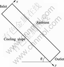
Fig.1 Schematic diagram of model system
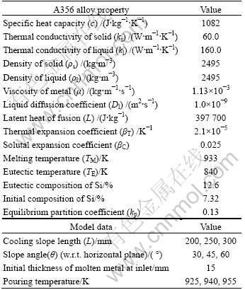
Table 1 Thermophysical properties and model data
3 Mathematical formulation
The solidification of alloy involves three distinct co-existing phases: a fully solidified region, a mushy region and fully liquid region. Here, the mushy region is modeled as a multi-layered porous medium consisting of fixed columnar dendrites mobile equiaxed/fragmented grains. A critical solid fraction referred to as coherency factor is used for demarcating the mobile and immobile zones. The fragmented dendritic particles and free equiaxed grains in the mobile non-coherent zone move by forced convection.
The flow resistance in the mushy region caused by the solid particles can be estimated by two methods. In the immobile coherent zone (i.e. in the region denoted by solid fraction above the critical value), the mushy region can be considered as a porous medium where the solid is stationary and the liquid flows through the porous structure, and Darcy��s law can be used for modeling flow resistance. In the mobile non-coherent zone where the mushy region can be treated as a mixture of freely moving solid phase and liquid, the flow resistance can be modeled by prescribing an appropriate viscosity model as a function of solid fraction.
This proposed model uses a fixed-grid continuum formulation with a single-domain approach based on the classical mixture theory[18-21] for solidification modeling. Using this fixed grid single domain approach, the interface comes out as a solution and is not required to track separately. Invoking assumptions consistent with the continuum model described in Ref.[18] and neglecting solidification shrinkage (��s=��l), the continuum density for the alloy phase is defined as follows.
 (1)
(1)
As shrinkage is neglected, the volume fraction (gk) and the mass fraction (fk) can be considered equivalent and interchangeable.
The VOF method[22] is used for tracking the interface between the alloy and air during flow on cooling slope. The volume of fraction of a control volume (F) has a range from zero to unity; the cells having F values between zero and one (0
 (2)
(2)
The properties appearing in the transport equations are determined by the presence of the component phases in each control volume. The density in each control volume is given by
 (3)
(3)
Other physical properties are also computed in a similar manner.
The most generalized governing transport equations for incompressible flow along with solidification are as follows:
1) Continuum definition
 (4)
(4)
 (5)
(5)
2) Continuity
 (6)
(6)
3) Momentum


 (7)
(7)
4) Energy

 (8)
(8)
5) Species

 (9)
(9)
The above model will be complete only if we have a sub-model to represent solid phase velocity relative to that of the liquid phase. As the flow of liquid alloy down the slope is essentially a forced convection driven phenomenon, it may be fair to assume, as a preliminary model, that the solid phase in the non-coherent mushy zone moves with the same velocity as that of the liquid. In other words, in the mushy zone below coherency point,
 (10)
(10)
The effective viscosity, ?eff, appearing in the momentum equation is the slurry viscosity that is a function of solid fraction, which in turn depends on temperature of alloy. The slurry viscosity was modeled as follows[26].
 (11)
(11)
where the solid fraction is calculated by using Scheil equation as follows.
 (12)
(12)
The coherency point after which solid cannot move is defined by gs, cr[27]. Below the coherency point the third term appearing in the momentum equation is forced to zero and once the coherency is reached, the third term dominates and acts like a source term for flow through porous medium. In the third term, K is defined as follows[18]:
 (13)
(13)
The term ?H appearing in the energy equation is the latent enthalpy of a cell. The calculation of the term ?H involves the instantaneous liquid fraction, which is predicted by an enthalpy updating technique[20-21], which will be discussed subsequently.
The term  appearing in the species equation is a representative value of solid concentration, obtained by averaging over the solid volume fraction defined in microscopic scale, as suggested by Scheil��s assumption[23]. It can be written as:
 (14)
(14)
4 Numerical scheme
The governing transport equations are solved numerically using the commercial CFD solver Fluent 6.3.26. The above-mentioned governing transport equations are converted into standard form as follows:
 (15)
(15)
The equations are discretized using a pressure based finite volume method according to the SIMPLER algorithm[24], where j represents any conserved variable and S is a source term. The source terms are included in the respective governing equations through the user defined functions in FLUENT.
The porous medium source terms in momentum equations are calculated for each control volume using the value of liquid fraction. The value of liquid fraction and solid fraction in the source terms of momentum, energy and species equations is calculated by using an enthalpy update scheme. The value of liquid fraction is given as  .
.
The thermal and concentration fields are calculated by solving the energy and species conservation equations (Eqs.(8) and (9)). The coupling between temperature and concentration fields is achieved through the temperature-concentration algorithm similar to the one described in Refs.[19, 21].
For an accurate prediction of the liquid fraction in the present ��fixed-grid enthalpy-based�� procedure, the latent heat content of each computational cell needs to be updated according to the temperature and/or species concentration values predicted by the macroscopic conservation equations, during each iteration within a time-step in an implicit way. In a physical sense, such updating attempts to neutralize the difference in the nodal temperature predicted from the energy equation and that dictated by the phase-change considerations. In the present context, an iterative updating scheme proposed in Ref.[21] is chosen, which is of the form:
 (16)
(16)
where,


In the above equation, aP is the coefficient of TP in the discretization equation of the governing energy equation, �� is a relaxation factor, F-1 is inverse of suitable latent heat function for a binary alloy with Scheil��s behavior depending on phase diagram of the solution, ��V is the volume of a computational cell centered on the grid point P and ��t is the time step. The term hP is the sensible enthalpy appropriate to the nodal point P.
An appropriate representation of the metal�Cair interface during alloy flow on cooling slope is achieved by deploying the VOF method available in Fluent along with a geometric reconstruction scheme[25]. The air�Calloy interface is sharp, such that this interface includes only one cell along the profile. The solute transport Eq.(9) is solved only in those cells where F=1. Solidification is suppressed in the cells having F<1 by avoiding enthalpy update in those cells.
5 Results and discussion
The final properties of the semisolid slurry at the exit of the cooling slope depend on various process parameters such as slope angle, slope length, cooling rate, pouring rate and initial superheat of the alloy. As a demonstration of the effectiveness of the numerical model developed, a parametric study is performed with respect to two key parameters, namely the slope angle and the pouring temperature. All other variables are kept constant. For the present simulations, a cooling slope of length of 250 mm and an inlet velocity of molten alloy A356 is 0.025 m/s (corresponding to a pouring rate of 0.935 625 kg/s) are chosen. The critical solid fraction for coherence is taken as 0.20 for all simulations.
5.1 Effect of slope angle
The slope angle �� (Fig.1) significantly influences the velocity and temperature distributions, the evolution of macrosegregation, solid fraction, exit temperature, and maximum velocity. Fig.2 shows the simulation results of velocity distribution for slope angles of 30�� and 60�� with respect to horizontal plane. Here, the computational domain chosen is of size 250 mm��15 mm. The pouring temperature is 940 K. The alloy accelerates down the slope after pouring, hence the flow cross sectional area at the exit is much smaller that at the inlet (Figs.2(a) and (b)). The velocity at the exit is 1.052 m/s and 1.288 m/s for slope angles of 30�� and 60��, respectively (Fig.2). As expected, the maximum velocity increases for a higher component of g along the slope direction.
The average solid fraction at the exit of the slope for various slope angles is shown in Table 2. As observed, the average exit solid fraction decreases with the slope angle. With increase in slope angle, the residence time of the alloy in the cooling slope deceases and hence the solidification time is less. Correspondingly, the simulation results of temperature distribution shown in Fig.3 suggest that a higher slope angle results in higher alloy temperature at the exit of the slope. However, a sufficiently high slope is required, nevertheless, to cause the necessary shearing of dendrites for slurry production. The desired solid fraction at the exit should, instead, be obtained by adjusting other control parameters such as slope length and cooling rate.
Table 2 Solid fraction at exit for various slope angles
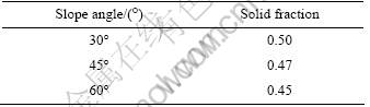
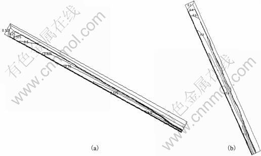
Fig.2 Velocity distribution with different slope angles: (a) 30��; (b) 60��
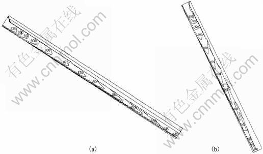
Fig.3 Temperature distribution with different slope angles: (a) 30��; (b) 60��
Fig.4 illustrates the evolution of macrosegregation (as mass fraction (%) of Si) as the molten A356 alloy flows on cooling slope. It may be observed that near the inlet, there is very little macrosegregation as solidification just begins. The species distribution changes as the alloy travels down the slope and progressively approaches the eutectic composition near the exit of the slope. The black layer in Fig.4 denotes air (above the flowing alloy), in which the species concentration is zero.
5.2 Effect of superheat
Fig.5 describes the simulation results of temperature distribution in A356 alloy while flowing on the cooling slope for two different pouring temperatures: 955 K and 925 K, in addition, the pouring temperature of 940 K is already taken in the previous case. Here, computational domain chosen is of size 250 mm��15 mm, which is the same as previous case and the slope angle is taken as 60��. The inlet velocity of molten alloy is 0.025 m/s, which corresponds to a pouring rate of 0.935 625 kg/s. Fig.6 shows that the temperature of alloy decreases along the flow direction, as expected. It can be seen that there is a sharper decrease in temperature with relatively high pouring temperature, which significantly affects the exit temperature of the alloy. The exit temperature increases with the pouring temperature that, in turn, decreases the exit solid fraction as determined from Scheil equation. The macrosegregation with different pouring temperatures is shown in Fig.6. As expected, the case with lower pouring temperature shows higher macrosegregation at the slope exit, as solidification in the case begins earlier.
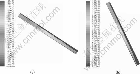
Fig.4 Macrosegregation with different slope angles: (a) 30��; (b) 60��
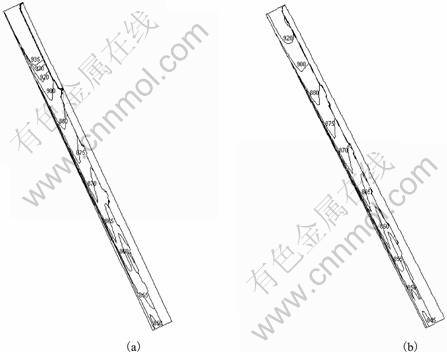
Fig.5 Temperature distribution with different pouring temperatures: (a) 955 K; (b) 925 K
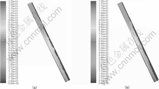
Fig.6 Species distribution with different pouring temperatures: (a) 955 K; (b) 925 K
6 Conclusions
1) A numerical model to predict solidification and macrosegregation during slurry preparation using a cooling slope is presented. Parameters affecting the slurry properties at the cooling slope exit are slope angle, degree of superheat, pouring velocity and slope length, as they affect the temperature distributions, the evolution of macrosegregation, solid fraction, exit temperature, and maximum velocity.
2) The model is demonstrated for the case of aluminum alloy A356 slurry preparation. Two key process parameters are studied in detail. The predictions of the model with regard to various process parameters are along expected lines.
3) Direct comparison with other numerical models for cooling slope is not possible due to non-availability of such models in the literature. However, experimental validation with an in-house experimental set-up is planned for the future.
Acknowledgements
The financial support from Ministry of Mines, TIFAC, Department of Science and Technology and Defence Research and Development Organisation is gratefully acknowledged.
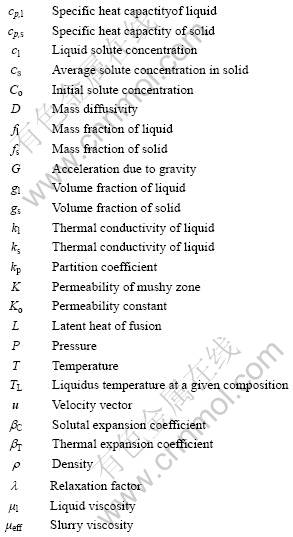
Nomenclature
References
[1] SPENCER D B. PhD Thesis [D]. MIT, Cambridge, MA, 1971.
[2] SPENCER D B, MEHRABIAN R, FLEMINGS M C. Rheological Behavior of Sn-15 % Pb in the Crystallization Range [J]. Metallurgical Transactions, 1972, 3: 1925-1932.
[3] MEHRABIAN R, FLEMINGS M C. Die castings of partially solidified alloy [J]. American Foundrymen Society Transactions, 1972, 80: 173-182.
[4] FAN Z. Semisolid metal processing [J]. Int Mater Rev, 2002, 47(2): 49-85.
[5] TAGHAVI F, SAGHAFIAN H, KHARRAZI Y H K. Study on the ability of mechanical vibration for the production of thixotropic microstructure in A356 aluminum alloy [J]. Mater Des, 2009, 30(1): 115-121.
[6] MOTEGI T, TANABE F, SUGIURA E. Continuous casting of semisolid aluminium alloys [J]. Mater Sci Forum, 2002, 396/397/398/399/400/401/402(1): 203-208.
[7] BIROL Y. Cooling slope casting and thixoforming of hypereutectic A390 alloy [J]. J Mater Proc Technol, 2008, 207(1/2/3): 200-203.
[8] QIN Q D, ZHAO YG, CONG PJ, ZHOU W, XU B. Semisolid microstructure of Mg2Si/Al composite by cooling slope cast and its evolution during partial remelting process [J]. Mater Sci Eng A, 2007, 444(1/2): 99-103.
[9] SALARFAR S, AKHLAGHI F, NILI-AHMADABADI M. Influence of pouring conditions in the inclined plate process and reheating on the microstructure of the semisolid A356 aluminum alloy [C]//. 8th International Conference on Semisolid Processing of Alloys and Composites, Cyprus, 2004.
[10] MOVAHEDI M, KARIMI A, NIA-MANESH H. Effect of angle of inclined plate on the microstructure of 7075 aluminum alloy [C]// 10th Congress of Iranian Institute of Materials and Metallurgy Engineering, Mashhad, Iran, 2006.
[11] GHASSEMI A. Investigation on the behavior of aluminum base alloys by applying inclined plate [D]. Iran University of Science and Technology, 2004.
[12] HAGA T, SUZUKI S. Casting of aluminium alloy ingots for thixoforming using a cooling slope [J]. Journal of Materials Processing Technology, 2001, 118: 169-172.
[13] HAGA T, KAPRANOS P. Simple rheocasting processes [J]. Journal of Material Processing Technology, 2002, 130/131: 594-598.
[14] GUAN R, ZHANG L, WANG C, WEN J, CUI J. Three dimensional analysis of the modified sloping cooling/shearing process [J]. Journal of University of Science and Technology Beijing, 2007, 14(2): 146-150.
[15] BIROL Y. A357 thixoforming feedstock produced by cooling slope casting [J]. J Mater Proc Technol, 2007, 186(1/2/3): 94-101.
[16] MEHRARA H, AHMADABADI M N, HEIDARIAN B, ASHOURI S, GHIASINEJAD J. Modeling of inclined cooling plate semisolid processing by model alloy [J]. Solid State Phenomena, 2008, 141/142/143: 785-790.
[17] LEGORETTA E C, ATKINSON H V, JONES H. Cooling slope casting to obtain thixotropic feedstock II: observations with A356 alloy [J]. J Material Science, 2008, 43: 5456-5469.
[18] BENNON W D, INCROPERA F P. A continuum model for momentum, heat, mass and species transport in binary solid-liquid phase change system: I. Model formulation [J]. Int J Heat Mass Transfer, 1987, 30: 2161-2170.
[19] VOLLER V R, BRENT A D, PRAKASH C. The modeling of heat, mass and solute transport in solidification systems [J]. Int J Heat Mass Transfer, 1989, 32 (9): 1719-1731.
[20] BRENT A D, VOLLER V R, REID K J. The enthalpy porosity technique for modeling convection-diffusion phase change: application to the melting of a pure metal [J]. Numerical Heat Transfer, 1988, 13: 297-318.
[21] CHAKRABORTY S, DUTTA P. A generalized formulation for evaluation of latent heat functions in enthalpy based macroscopic models for convection-diffusion phase change processes [J]. Metall Mater Trans B, 2001, 32: 562-564.
[22] HIRT C W, NICHOLS B D. Volume of fluid (VOF) method for the dynamics of free boundaries [J]. J Comput Phys, 1981, 39: 201-225.
[23] FLEMINGS M C. Solidification processing [M]. New York: McGraw-Hill, 1974.
[24] PATANKAR S V. Numerical heat transfer and fluid flow [M]. Washington D C: Hemisphere Publication, 1980.
[25] Fluent 6.3.26 Documentation �C User��s Guide and UDF Manual [M]. Lebanon, USA, 2005.
[26] OLDENBURG C M, SPERA F J. Hybrid model for solidification and convection [J]. Numerical Heat Transfer B, 1992, 21: 217-229.
[27] GU J P, BECKERMANN C, GIAMEI A F. Motion and remelting of dendrite fragments during directional solidification of a nickel-base super alloy [J]. Metall Mater Trans A, 1997, 28: 1533-1542.
(Edited by HE Xue-feng)
Corresponding author: P. DUTTA; Tel: +91-80-23604536; E-mail: pradip@mecheng.iisc.ernet.in

