J. Cent. South Univ. Technol. (2009) 16: 1022-1027
DOI: 10.1007/s11771-009-0169-1

Quantitative description of infrared radiation characteristics for
solid materials subjected to external loading
WANG Fang(王 芳)1, 2, LI Ying-jun(李英骏)1, RAO Qiu-hua(饶秋华)3 , TANG Lian(唐 炼)2
(1. School of Mechanics and Civil Engineering, China University of Mining and Technology (Beijing),
Beijing 100088, China;
2. Department of Mathematics-Physics, China University of Petroleum (Beijing), Beijing 102249, China;
3. School of Civil and Architectural Engineering, Central South University, Changsha 410075, China)
Abstract: Based on the thermodynamics theory and physical micro-properties of solid materials subjected to external loading at room temperature, a formula of calculating temperature difference of infrared radiation in terms of the sum of three principal strains was deduced to quantitatively investigate the infrared radiation characteristics in test. Two typical specimens, the three-point bending beam and the disc pressed in diameter, were tested and their principal strains were calculated by finite element method in order to obtain the temperature differences of infrared radiation. Numerical results are in a good agreement with test results, which verifies the validity of the formula of calculating temperature differences of infrared radiation and the model of quantitatively describing the infrared radiation characteristics of solid materials, and reveals the corresponding inner physical mechanism.
Key words: Infrared radiation characteristics; thermodynamics analysis; numerical simulation; strain tensor
1 Introduction
With rapid development of industry and continuous deterioration of global environment, earth disaster (e.g., earthquake and fracture) and industry calamity (e.g., coast and collapse) continuously increase and engineering safety is a striking problem. It is well known that fracture and instability of rock mass result in safety problem. Abnormal phenomena of surface thermal field (e.g., satellite thermal infrared image and surface latent heat flux) appearing before the medium strongtectonic earthquake indicate that the change in temperature is one of the most important influencing factors for these solid disasters[1-2]. Therefore, testing the temperature of solid materials subjected to external loading is of significance in engineering safety.
As the remote sensing technology develops, the thermal infrared thermography has been widely applied to measuring infrared radiation temperature owing to its predominant advantages including rapid response time (less than 100 ns), no physical contact with the deforming body, full-field, non-destructive nature and real time. Since 1988 when many moderate-strong earthquakes occured in the Central Asia and the Mediterranean sea[2], followed by satellite thermal infrared anomalies[3], numerous infrared radiation detecting tests have been used to study the infrared radiation temperature field of solid materials (such as metal, crystal, photo-elastic, concrete and some rock-like materials[3-6]) subjected to arbitrary loading (including uniaxial loading, biaxial loading and three-point bending[7-9]). Lots of thermal infrared imaging patterns and infrared radiation characteristics reflected on the patterns have been achieved.
Experimental results show that different solid materials under different loading conditions have different infrared radiation characteristics, but they have the same relationship between the solid deformation and the corresponding thermal infrared radiation, i.e., (1) both elastic and plastic deformations change the infrared radiation temperature of the body; (2) tensile elastic deformation results in an increase of volume and a decrease of temperature, while compressive elastic deformation is opposite; (3) most of irreversible work done on the material is converted to heat during plastic deformation and results in an increase of the body temperature. Obviously, infrared radiation characteristics can not only directly reflect the deformation and mechanical properties of the solid materials under loading, but also provide basic study for thermal infrared thermography theory, which is helpful for preventingearth disaster and improving engineering safety. Therefore, it is essential to study the infrared radiation characteristics of solid materials.
Currently, many researchers have focused on qualitative analysis and explanation without quantitative description of infrared radiation characteristics and analyses of inner physical mechanism[10-14]. In this work, infrared radiation characteristics of solid materials subjected to external loading at room temperature were quantitatively studied. A formula of calculating temperature difference of infrared radiation was deduced based on the principle of infrared thermograph and the thermodynamics. Two typical experimental examples were numerically analyzed by finite element method in order to verify the validity of the formula and reveal the inner mechanism of the infrared radiation characteristics.
2 Formula deduction of temperature field
The body is divided to many micro-units and the micro-unit is taken as the thermodynamic system. According to the solid mechanics, the infrared radiation of solid materials subjected to external loading at room temperature mainly results from vibration of atoms. In the initial stage of loading, the effect of external force exerted on the atom system can only change the balance position of atom vibration system except the structure of chemical bond. The deformation of body probably causes the rotation of molecule rather than the movement of molecule. Therefore, the volume of micro-units is almost constant under loading. In addition, the condition of equal temperature for micro-units is also satisfied by omitting heat exchange between the body and ambience at room temperature. As a result, the loading process of micro-units is approximately considered as an isoentropic adiabatic process based on thermodynamic criterion[15]:
 (1)
(1)
where S is the entropy of thermodynamic system; T is the temperature of system; and V is the volume of system.
From the following thermodynamic relationships:
 (2)
(2)
the formula of calculating temperature difference (dT) is easily obtained:
 (3)
(3)
where K is the elastic modulus; α is the thermal expansion coefficient; cV is the heat capacity; ρ is the density at room temperature; and εV is the sum of three principal strains.
 (4)
(4)
When εV<0 in compression, there exists dT>0 in Eq.(3), i.e., an increase of temperature occurs. When εV>0 in tensile, there exists dT<0, i.e., a decrease of temperature occurs.
It is well known that a body at temperature higher than 273 K will continuously emit electromagnetic radiation. The emitted radiation in a temperature range of 300-2 000 K is in the range of infrared wavelength, which can be measured by infrared detector. The total radiant energy flux per unit area (Φ) is calculated by the Stefan-Boltzman law[16]:
Φ=eBT4 (5)
where B is Stefen-Boltzman constant (B=5.67×10⁻⁸ W/(m2?K4)); e is the surface emittance of the body (material constant). Obviously, the radiant energy change dΦ can be calculated by using Eqs.(3) and (5) and thus the infrared radiation characteristics (i.e., infrared temperature field) of elastic deformation of solid materials can be quantitatively described.
3 Experimental and numerical studies
3.1 Test arrangement
Two typical specimens, three-point bending beam and disc pressed in diameter, were selected. The material is photo-elastic epoxy resin with obvious infrared radiation characteristics of elastic deformation. Table 1 lists its mechanical and physical properties at room temperature of 20 ℃.
Table 1 Mechanical and physical properties of material
Fig.1 shows the schematic diagram of three-point bending beam specimen of 80 mm×20 mm×6 mm in size. The external load is applied on the midline of top surface of the beam, and the span between the two bottom supporters is 72 mm. Eight points on two sections, midline section (x=40 mm) and right section (x=60 mm) are selected as typical points to calculate the stress and strain, i.e., 1(40, 20), 2(40, 15), 3(40, 10), 4(40, 5), 5(40, 0), 6(60, 15) 7(60, 10), 8(60, 5), where numbers in the bracket represent the coordinate value of the point.
Fig.2 shows the schematic diagram of disc pressed in diameter. The specimen is 50 mm in diameter and 6 mm in thickness. The loading velocity is 3 mm/min. Two points, loading point A and center point B, are selected as typical points respectively.
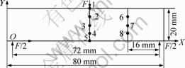
Fig.1 Schematic diagram of three-point bending beam
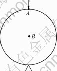
Fig.2 Schematic diagram of disc pressed in diameter
All of the tests were carried out on an electronic universal testing machine, AutoGraph AGS-H5KN, with a capacity of 5 kN under position control. The loading rate was 3 mm/min and the temperature was 20 ℃. The infrared thermographs of the specimens were measured by a highly-accurate infrared thermal imager, TVS-8 100 MK model II, with a temperature sensitivity of 0.025 ℃, pixel resolution of 160×120, wave band of 3.6-4.6 mm and image acquisition speed of 60 frame/s. Infrared thermal imager was located at a fixed distance of 1 m away from the specimens. In order to avoid reflection and scattering of light, all windows of room were covered by black curtains during the tests.
3.2 Finite element(FE) model
A three-dimensional finite element software ABQUS was used to calculate the principal strain, and two-dimensional shell element, CPS4R, was applied. Fig.3 shows finite element meshes of the three-point bending beam. The numbers of element and node were 6 400 and 6 601, respectively. Boundary condition was added by fixed and movable hinge supporters. The concentrated load was 3 kN at an incremental step of 300. For the disc pressed in diameter (Fig.4), the numbers of element and node were 9 400 and 9 559, respectively. The fixed hinge supporter was added and the concentrated load was 4.8 kN at an incremental step of 480. For comparison, material parameters were the same as those in experimental study (Table 1).

Fig.3 FE meshes of three-point bending beam
Fig.4 FE meshes of disc pressed in diameter
3.3 Results and analysis
3.3.1 Three-point bending beam
Fig.5 shows numerical results of the principal strains ε11 and ε22 of the three-point bending beam. Fig.6 shows test results of the corresponding infrared radiation imaging pattern, which is a picture of color density intersection indicating temperature difference (dT). The color is usually divided as 10 grades, white, yellow, orange, light red, red, light green, green, light blue, deep blue and black, corresponding to temperature from high to low. Each grade of color has the temperature difference of 0.1 ℃.
It can be seen that εV in compressive stress zone
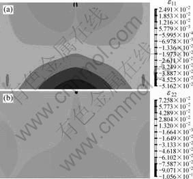
Fig.5 Numerical results of principal strains of three-point bending beam: (a) ε11; (b) ε22
(e.g., points 1, 2 and 6) is negative and dT is positive based on Eq.(3), which are in a good agreement with the infrared radiation characteristics of warm color in this zone of Fig.6. Furthermore, point 1 has the largest value of dT, meaning that the temperature at the action point of loading is increased to the maximum, which can be found by infrared radiation characteristics of deep red color near point 1 in the imaging pattern. When the point is located in tensile stress zone (e.g., points 4, 5 and 8), εV is positive and dT is negative, indicating the decrease of its temperature, which can be described by infrared radiation characteristics of cool color in the imaging pattern. Therefore, the distribution of the sum of three principal strains can be used to obtain inner temperature field for solid materials subjected to external loading.
In order to verify ulteriorly, Fig.7 shows numerical results of temperature difference (dT) varying with
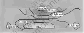
Fig.6 Infrared radiation imaging pattern of three-point bending beam
external loading F (0-2.5 kN) of eight typical points as well as the testing results for comparison.
It is seen that the numerical results of the temperature difference at each point are larger than the testing results probably because energy loss and some interfering factors existing in thermal infrared thermograph testing are not taken into account. The result is helpful for forecasting and preventing earth disaster and improving engineering safety. Points 1 and 5 located on the specimen surface have more external interference and thus larger deviation from the test results. The comparison of Figs.7(b) and (c) shows that points 2 and 4 located in the stress concentration zone have greater temperature difference than points 6 and 8 outside the stress concentration zone when the load is increased. In general, the tendency of the temperature difference varying with the load obtained by calculation is well coincident with that by testing. Therefore, Eq.(3) is reasonable and feasible for the dynamic analysis in error range.
3.3.2 Disc pressed in diameter
Fig.8 shows numerical results of principal strains ε11 and ε22 of the disc pressed in diameter and Fig.9 shows the testing result of the corresponding infrared radiation imaging pattern. It can be seen that most values of ε11 and ε22 are negative. Therefore, the sum of three
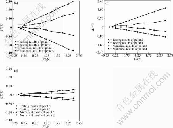
Fig.7 Numerical and testing results of temperature difference varying with external loading for three-point bending beam: (a) Points 1 and 5; (b) Points 2 and 4; (c) Points 6 and 8
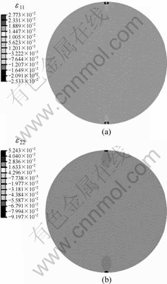
Fig.8 Numerical results of principal strains of disc pressed in diameter: (a) ε11; (b) ε22
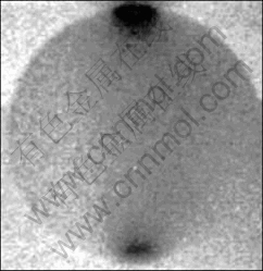
Fig.9 Testing result of infrared radiation imaging pattern of disc pressed in diameter
principal strains εV is negative basically and dT is positive based on Eq.(3), which are in a good agreement with infrared radiation characteristics of warm color under loading.
Similarly, Fig.10 shows the numerical results of the temperature difference dT varying with external load F (0-4.8 kN) of points A and B as well as the testing results for comparison. The numerical results of dT at point A is larger than the testing results, because point A located on the specimen surface and in the stress concentration zone has more energy loss during the test. Therefore, larger error exists for point A when the load is larger than 2 kN in the test. For point B located at the center point of the disc specimen, the numerical results dT varying with the load coincide with the testing results quite well.
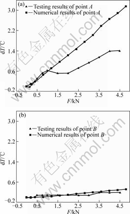
Fig.10 Numerical and testing results of temperature difference varying with external loading for disc pressed on diameter: (a) Point A; (b) Point B
4 Conclusions
(1) The deduced formula of calculating temperature difference of infrared radiation in terms of the sum of three principal strains is reasonable and feasible for quantitatively describing the infrared radiation characteristics of solid materials in elastic deformation, which is proved by testing results of the three-point bending beam and the disc pressed in diameter.
(2) The elastic deformation process of solid is approximatively an isoentropic adiabatic thermodynamic process. The infrared radiation characteristics of solid materials in elastic deformation result from the vibration of atoms and the radiation flux from the change of atom vibrant system in microscopic mechanism.
(3) This research method can be applicable for quantitatively describing infrared radiation chara- cteristics of other solid materials at initial stage of loading, such as rock-like materials with complex structure in geologic and petroleum geologic mechanics.
References
[1] LIU Shan-jun, YANG Dong-ping, MA Bao-dong, WU Li-xin, LI Jin-ping, DONG Yan-qing. On the features and mechanism of satellite infrared anomaly before earthquakes in Taiwan region[C]//Geoscience and Remote Sensing Symposium. Barcelona, 2001: 3719-3722.
[2] GORNYI V I, SALMAN A G, TRONIN A A, SHILIN B B. The earth outgoing IR radiation as an indicator of seismic activity[J]. Proc Acad Sci USSR, 1988, 30(1): 67-69.
[3] LUONG M P. Fatigue evaluation of metals infrared thermography[C]//The Second International Conference on Experimental Mechanics. Singapore, 2001: 297-302.
[4] WU Li-xin, ZHONG Sheng, WU Yu-hua. Fundamental research on remote sensing the strain and catastrophe of concrete under uniaxial compression[J]. International Geoscience and Remote Sensing Symposium, 2005(3): 1760-1763.
[5] WU Li-xin, LIU Shan-jun, WU Yu-hua, WU Huan-ping. Changes in infrared radiation with rock deformation[J]. International Journal of Rock Mechanics and Mining Science, 2002, 39: 825-831.
[6] ZHANG Dong-sheng, AN Li-qian, ZHANG Yong-jun. IR thermograph characteristics of photoelastical material in loading[J]. Journal of Experimental Mechanics, 2001, 16: 444-449. (in Chinese)
[7] WU Li-xin, ZHONG Sheng, WU Yu-hua, WANG Chuan-ying. Precursors for rock fracturing and failure. Part I: IRR image abnormalities[J]. International Journal of Rock Mechanics and Mining Sciences, 2006, 43: 473-482.
[8] SHI Wen-zhong, WU Yu-hua, WU Li-xin. Quantitative analysis of projectile impact on rock using infrared thermography[J]. International Journal of Impact Engineering, 2007, 34: 990-1002.
[9] WU Li-xin, ZHONG Sheng, WU Yu-hua, WANG Chuan-ying, ZHANG Ling. Time dependent features of thermal infrared radiation temperature of rock impacted by free-falling steel ball[J]. Journal of China University of Mining and Technology, 2005, 34(5): 557-563. (in Chinese)
[10] PANDEY K N, CHAND S. Deformation based temperature rise: A review[J]. International Journal of Pressure Vessels and Piping, 2003, 80: 673-687.
[11] AN Li-qian, ZHANG Dong-sheng. Quantitative analysis between infrared temperature field and photo-elastic stress field[C]//Proceedings of the 21st International Symposium on Computer Application in Minerals Industries. Beijing, 2001: 689-692.
[12] LUO W B, YANG T Q, LI Z D, YUAN L W. Experimental studies on the temperature fluctuations in deformed thermoplastics with defects[J]. International Journal of Solid and Structure, 2000, 37: 887-897.
[13] ZHANG Yong-jun. Study on IR radiation regular pattern pattern of photoelastic material under loading and correlative studies[D]. Beijing: China University of Mining and Technology (Beijing), 2003. (in Chinese).
[14] ZHANG Dong-sheng. Study on infrared temperature field and isochromatics of the photoelastic material loaded[D]. Beijing: China University of Mining and Technology (Beijing), 2000. (in Chinese)
[15] EBERT M M,RANNESS H C. Thermodynamics theory and exercises[M]. Beijing: Chemical Industry Press, 1976: 47-113.
[16] CHEN Heng. Infrared physics[M]. Beijing: National Defense Industry Press, 1985. (in Chinese)
(Edited by CHEN Wei-ping)
Foundation item: Projects (10775018, 10702010, 50374073) supported by the National Natural Science Foundation of China; Project(2002CB412701) supported by the National Basic Research Program of China
Received date: 2009-04-02; Accepted date: 2009-07-30
Corresponding author: RAO Qiu-hua, Professor; Tel: +86-731-88836001; E-mail: raoqh@mail.csu.edu.cn

