Bearing characteristics and fatigue damage mechanism of multi-pillar system subjected to different cyclic loads
��Դ�ڿ������ϴ�ѧѧ��(Ӣ�İ�)2020���2��
�������ߣ�����Ȫ ������ ���� 갺��� ��� ����
����ҳ�룺542 - 553
Key words��multi-pillar system; cyclic loading; fatigue damage; bearing characteristics; acoustic emission (AE); digital image correlation (DIC)
Abstract: Aiming to investigate the fatigue damage mechanism and bearing characteristics of multi-pillar system under cyclic loading, a series of axial cyclic loading tests with different cyclic amplitudes were carried out on triple-pillar marble specimens. The acoustic emission (AE) and digital image correlation (DIC) were jointly applied to monitoring and recording damage evolution and failure behavior of each pillar, which reproduced the cataclysmic instability process of underground pillar groups. Experimental results indicated that the cyclic amplitude exceeding the threshold of damage initiation weakened the resistance to deformation, resulting in obvious release of dissipated energy and the reduction of bearing capacity. Conversely, after low-amplitude cyclic loading, both the pre-peak bearing capacity and the post-peak ductility of the pillar system increased due to the compaction of initial defects, indicating that the peak bearing capacity was closely related to the extent of pre-peak fatigue damage. The axial strain of each pillar was measured by DIC virtual extensometer to present the damage extent during cyclic loading phase. Meanwhile, fracture evolution of typical load drop points was also characterized by transverse strain fields (��xx), and observations showed that the damage extent of key pillar undergoing high-amplitude cyclic loads was more serious and violent, accompanied by the ejection of rock debris and loud noises.
Cite this article as: ZHOU Zi-long, WANG Hai-quan, CAI Xin, ZANG Hai-zhi, CHEN Lu, LIU Fu. Bearing characteristics and fatigue damage mechanism of multi-pillar system subjected to different cyclic loads [J]. Journal of Central South University, 2020, 27(2): 542-553. DOI: https://doi.org/10.1007/s11771-020-4315-0.

J. Cent. South Univ. (2020) 27: 542-553
DOI: https://doi.org/10.1007/s11771-020-4315-0

ZHOU Zi-long(������)1, WANG Hai-quan(����Ȫ)1, CAI Xin(����)1,ZANG Hai-zhi(갺���)1, CHEN Lu(���)1, 2, LIU Fu(����)1, 3
1. School of Resources and Safety Engineering, Central South University, Changsha 410083, China;
2. School of Civil Engineering, Changsha University of Science and Technology, Changsha 410076, China;
3. Guangxi Communications Design Group Co., Ltd., Nanning 530022, China
 Central South University Press and Springer-Verlag GmbH Germany, part of Springer Nature 2020
Abstract: Aiming to investigate the fatigue damage mechanism and bearing characteristics of multi-pillar system under cyclic loading, a series of axial cyclic loading tests with different cyclic amplitudes were carried out on triple-pillar marble specimens. The acoustic emission (AE) and digital image correlation (DIC) were jointly applied to monitoring and recording damage evolution and failure behavior of each pillar, which reproduced the cataclysmic instability process of underground pillar groups. Experimental results indicated that the cyclic amplitude exceeding the threshold of damage initiation weakened the resistance to deformation, resulting in obvious release of dissipated energy and the reduction of bearing capacity. Conversely, after low-amplitude cyclic loading, both the pre-peak bearing capacity and the post-peak ductility of the pillar system increased due to the compaction of initial defects, indicating that the peak bearing capacity was closely related to the extent of pre-peak fatigue damage. The axial strain of each pillar was measured by DIC virtual extensometer to present the damage extent during cyclic loading phase. Meanwhile, fracture evolution of typical load drop points was also characterized by transverse strain fields (��xx), and observations showed that the damage extent of key pillar undergoing high-amplitude cyclic loads was more serious and violent, accompanied by the ejection of rock debris and loud noises.
Key words: multi-pillar system; cyclic loading; fatigue damage; bearing characteristics; acoustic emission (AE); digital image correlation (DIC)
Cite this article as: ZHOU Zi-long, WANG Hai-quan, CAI Xin, ZANG Hai-zhi, CHEN Lu, LIU Fu. Bearing characteristics and fatigue damage mechanism of multi-pillar system subjected to different cyclic loads [J]. Journal of Central South University, 2020, 27(2): 542-553. DOI: https://doi.org/10.1007/s11771-020-4315-0.
1 Introduction
As global society continues to extract ore from ever-increasing depths of the earth, large mined-out areas are often left in deep underground [1-4]. Unexploited pillars embedding in the rock mass, as a kind of underground frame structure after extraction, are intentionally retained temporarily or permanently to support the roof of excavated areas [5-7]. The overall stability of mined-out areas principally depends upon the bearing capacity of remained pillars, especially in the process of deep underground mining [8-11]. Hence, it is highly worth to investigate the deformation and failure behavior of multiple pillars in complex external conditions.
Due to the non-repairable feature of pillar failure, the instability of goaf and pillar has been attracting a growing attention from researchers and policy makers in main countries with highly developed mining industry. Considerable efforts have been devoted to investigating the failure mechanism of multiple pillars using various approaches. Five case studies of collapse of surface crown pillars from Western Australia and the Northern Territory were analyzed for pre- and post-failure behavior of rock mass by SZWEDZICKI [12]. In order to obtain better understanding of the mechanism of the 1873 panel collapse at the Varangeville salt mine, BEREST et al [13] conducted numerical computations to confirm that the central pillar punched the floor and thereby resulted in large-scale deformation of roof and catastrophic evolution of pillar punching. WANG et al [14] made a comprehensive analysis of the pillar instability and the fracture process in the roof strata from the technical viewpoint of air shock and ground stability to investigate the causation of catastrophic ground collapse in Xingtai gypsum mines in 2005. Progressive failure process and associated acoustic emission behavior of serial and parallel rock samples were simulated by WANG et al [15] using a numerical modelling code, RFPA2D. CORDING et al [7] developed a design approach for pillar size and loading taking into account the pillar height and the quality of rock mass to evaluate the overall stability of the pillars in mined gas storage caverns. In terms of experimental research, the evolution mode of sudden surface collapse caused by shallow partial mining was proposed by CUI et al [16] through introducing efficient pillar widths and using the Voronoi diagram, which was subsequently verified by ��similar material simulation��. ZHOU et al [17] and ZHU et al [18] conducted a series of tests on large-scaled multiple-pillar models. They comprehensively revealed the failure characteristics of multi-pillar system such as incompatible deformation, load transfer, and progressive failure during the process of instability failure. Nevertheless, the above-mentioned works are limited in static conditions, which fail to reflect the actual stress state of underground pillars.
In practical engineering applications, underground structures always undergo cyclic disturbance probably from mechanical excavation, drilling operations, blasting vibration and seismic events [19-26]. Cyclic loads may trigger the instability of mined-out areas and even catastrophic progressive pillar collapses [12-14, 27, 28]. A large number of previous studies show that cyclic loading brings fatigue damage to rock and obviously affects the bearing capacity of rock [29-34]. Particularly, SONG et al [35, 36] carried out cyclic uniaxial compression tests with different amplitudes on Yunnan sandstone using digital image correlation (DIC). They found that the cyclic loading with larger amplitude had a significant influence on the rock strength, namely the peak load decreased with the increase of cyclic amplitude. However, the research object is only a single rock block, and the influence of cyclic load on the bearing characteristics of multi-pillar system remains unclear.
To understand bearing characteristics and damage mechanism of underground pillar groups subjected to cyclic loading, different cyclic amplitudes are selected to perform on triple-pillar marble specimens, thereby revealing instability mechanism of the occurrence of cascading pillar failure in underground mine.
2 Experimental
2.1 Specimen preparation
Rock material used in this study was white marble collected from an underground metal mine in Yunnan province, China. The mineral composition analysis indicates that this marble is primarily comprised of dolomite (93.2%), carbonaceous substance (4.8%) and opaque minerals (2%). The white marble was classified as semidiomorphic-idiomorphic crystal dolomite with irregular granular and blocky mosaic structure. Before testing, cylindrical specimens with 50 mm in diameter and 100 mm in length were taken from the same intact rock block for basic mechanical properties testing. Some basic physical and mechanical parameters were also measured, as listed in Table 1.
All specimens were obtained from a single marble block. Several marble plates with dimensions of 260 mm��200 mm��50 mm (length�� height�� width) were first sliced. Then three prisms of 50 mm��50 mm��100 mm and span of 30 mm were manufactured, as shown in Figure 1,which simulates the residual pillars from underground mine. The top and bottom (50 mm in height) of specimen could be considered the roof and floor, respectively. In order to reduce test error, the surface flatness of all specimens was polished and controlled within �� 0.05 mm, and adjacent verticality deviation between two surfaces was kept within �� 0.5��. Besides, artificial random speckles were sprayed on the front surface of three pillars before testing to monitor the apparent strain of each pillar.
Table 1 Summary of basic mechanical and physical parameter of marble specimen
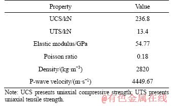
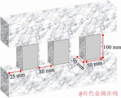
Figure 1 Experimental specimen with three prisms
2.2 Experimental apparatus
The schematic illustration of the experimental set-up is shown in Figure 2. It can be seen that the experimental apparatus includes a loading system, an acoustic emission (AE) acquisition system and a digital image correlation (DIC) system. These apparatuses were triggered simultaneously to acquire and record mechanical data, AE information and speckle images throughout the whole testing process. Respective testing technique is introduced in detail in the following sections.
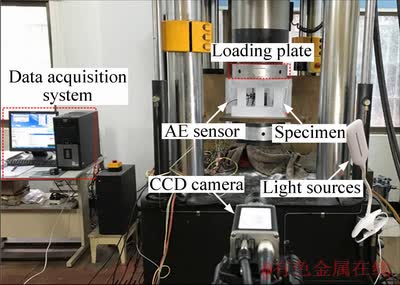
Figure 2 Schematic diagram of experimental setup
2.2.1 Loading system
All tests were performed on a servo-controlled material testing machine (INSTRON 1346) in the Advanced Research Center at Central South University. The maximum loading capacity of the test machine was 2000 kN. Multiple load control modes, such as displacement control, load control and strain control, can meet the test requirements. The load measurement accuracy was �� 0.5% and the maximum frequency of data acquisition system was 500 Hz. The acquisition frequency of testing data was set to 10 Hz in this study.
2.2.2 Acoustic emission system
As known, the rupture of rock material causes the local strain energy to be released rapidly and generate transient elastic waves, which is also called acoustic emission (AE) [37, 38], and the transient elastic waves in materials can be received by AE sensors. The AE acquisition system produced by Physical Acoustics Corporation (PAC) was employed to monitor and record the AE activity information of each pillar in real time, which can effectively identify the internal damage evolution information of rock material [39]. Two Nano30 sensors were attached on the surface of each pillar to record the AE activity event. The preamplifier (PAC 2/4/6) was set 40 dB to avoid noise interference from potential electronic devices and AE signals of rock fracture whose amplitude exceeded 45 dB were acquired and stored in the computer.
2.2.3 Digital image correlation technique
Digital image correlation (DIC) can provide an effective method for measuring the full-field strain on the rock surface during deformation process [17, 18, 35, 36, 40-42]. The basic principle of DIC technique is to track the same pixel point based on the assumption that the gray value of the selected image remains unchanged before and after deformation. In this study, a charged couple discharge (CCD) camera (Basler PiA2400-17 gm) under the illumination of a spotlight was applied to capturing images. Specific settings for the CCD camera keep constant during the whole loading process as 2448��2050 pixels for the view field of 100 mm��220 mm at the exposure rate of 15 frames per second.
2.3 Loading scheme
To determine the amplitude of the applied cyclic loads, axial compression tests were carried out on triple-pillar specimens. The average axial bearing capacity of triple-pillar specimens was approximately 929.28 kN. The AE event of specimen increased slightly after the load reached to 322.96 kN. To reveal the failure characteristics and bearing capacity of multiple pillars under cyclic loading, 200 and 400 kN were designed as cyclic amplitude loads respectively. In tests, the loading process was divided into two stages, namely cyclic loading phase and axial compression phase. The loading path is shown in Figure 3. Five loading- unloading cycles were applied to simulating engineering cyclic disturbance with a constant loading rate of 2 kN/s, and then specimens were compressed under a constant displacement speed of 0.2 mm/min until failure. In order to reduce the discretization of test results, five specimens were prepared in each group. It is worth pointing out that, before testing, the specimens must be placed on the center of the loading platform to ensure that the sample can be uniformly compressed.
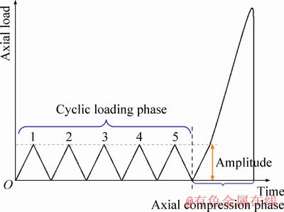
Figure 3 Loading path of axial cyclic tests
3 Results and discussion
3.1 Axial deformation behavior
The typical load-displacement curves are shown in Figure 4. Under the same cyclic load beyond the threshold of damage initiation, the specimen subjected to pre-cyclic load with higher amplitude possesses the largest axial displacement, and that of low-amplitude cyclic test is the smallest, meaning that the high-amplitude load weakens the deformation resistance of pillar system, whereas pre-cyclic load with lower amplitude has hardening effect. The axial strain of each pillar between two points from bottom to top is calculated using DIC virtual extensometer, as shown in Figure 5(a).
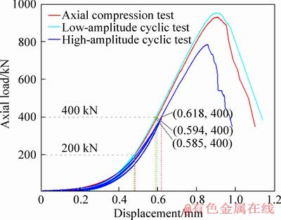
Figure 4 Load versus displacement curves of different testing schemes
In Figures 5(b) and (c), during the cyclic loading phase, the axial strain of each pillar in the high-amplitude cyclic test is approximately three times larger than that of the low-amplitude cycle test, leading to obvious axial deformation. Due to the influence of rock properties or loading conditions, there is a key pillar in each pillar system, which first produces large axial strain, such as pillar-I in high-amplitude cyclic test and pillar-III in low-amplitude cyclic test. Additionally, the axial strain of the key pillar of high-amplitude cyclic test increases significantly from the fourth cycle, earlier than that of the fifth cycle of the low-amplitude cyclic test. The above phenomenon demonstrates that the damage of pillar system increased accumulatively with the increase of cycle number and mainly reflected in the key pillar.
It is noted that the deformation of the specimen behaved strong nonlinearity under the high-amplitude cyclic load, and obvious plastic hysteresis loops occurred in the load-displacement curves. Figure 6 shows that the area of first plastic hysteretic loop is the largest, thereafter the plastic hysteresis loop continues to occur but the area gradually maintains constant with the increase of cyclic number. Due to the accumulation of plastic deformation in each loading cycle, the newly formed plastic hysteresis hoop migrated in the direction of increasing displacement. The explanation for above phenomenon is that in the first cycle the compaction of original micro-crack and the generation of new crack consume the energy of pillar system, then the original micro- crack disappears and the new crack generation gradually decreases under the same cyclic load.
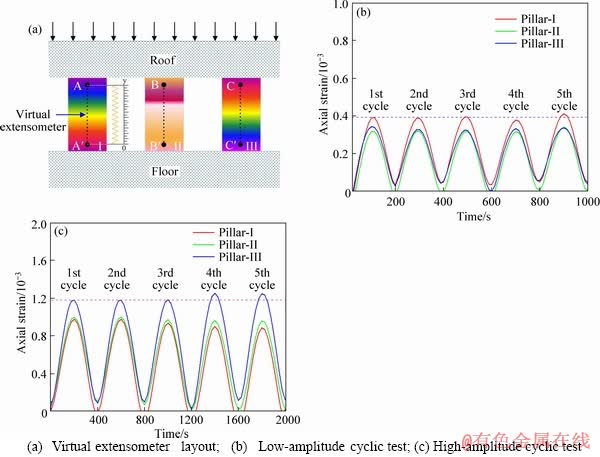
Figure 5 Axial strain of each pillar measured by digital image correlation (DIC) during cyclic loading phase:
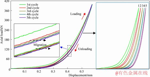
Figure 6 Variation of plastic hysteresis loop in high-amplitude cyclic test
3.2 Energy dissipation rule
As is known, the specimen always exchanges energy with surrounding system during cyclic loading. The amount of dissipated energy Ud during one single loading-unloading process can reflect the irreversible damage inside the rock specimen induced by external load, which can be calculated by the area of the hysteresis loop in the load-displacement curve [43-47]. The dissipated energy can be divided into two categories [48]: class I is also called damage energy used to crack initiation, propagation and plastic deformation, and class II: energy is consumed in heat convection, conduction and radiation of seismic energy [49]. The dissipated energy of specimens for different cyclic loading levels is depicted in Figure 7. The variation trend for two cyclic loading levels is highly similar, namely, the dissipated energy has the peak value in the first cycle, and then apparently decreases and maintains nearly constant during the following cycles. Similar observation is consistent with the previous work by SONG et al [35] for sandstone specimens. DATTOMA et al [50] proved that the class II energy almost remains constant under the same cyclic loading using infrared thermography technique. Therefore, it can be inferred that, during cyclic loading process with these two designed amplitudes, the deterioration of rock induced by external load mainly occurs in the first cycle. The dissipated energy in the first cycle of specimen under 200 kN amplitude is significantly lower than that under 400 kN amplitude, indicating that higher loading level causes greater damage in rock.
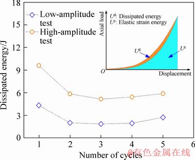
Figure 7 Variation of dissipated energy during cyclic loading phase
3.3 AE evolution characteristics
The failure process of rock mass is controlled by internal damage initiation and propagation induced by external load [51, 52]. The variations of AE ringing count can well characterize micro-damage inside the rock. In order to characterize AE damage evolution of pillar system, Figure 8 depicts the variation of the ringing count of each pillar during cyclic loading phase. It can be found that the similar AE evolution trend of three pillars is shown under both loading conditions. AE ring counts from the 1st to 2nd cycle are generated only at the loading phase, whereas in the 3rd to 5th cycle, they occur in both the loading and unloading phases. However, due to the loading and unloading effect of high amplitude load, the quantity of AE ringing counts is approximately three times as much as that of the low-amplitude cyclic test.
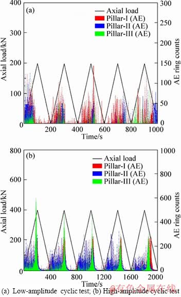
Figure 8 AE evolution characteristic of each pillar during cyclic loading phase:
A possible explanation for this may be that the applied load on the specimen exceeds its threshold of damage initiation and causes irreversible damage; another explanation is that the unloading process results in free propagation of new cracks, which increases the probability of friction between rock particles, and thus generates more AE ringing counts. Variations of cumulative AE counts of each pillar at different cyclic loading stages are depicted in Figure 9.
The evolution trend of AE ringing counts in Figure 9 matches well with the dissipated energy Ud of the plastic hysteresis loops in Figure 7, further indicating that the AE information obtained from the rock can well characterize the damage behavior of each pillar.
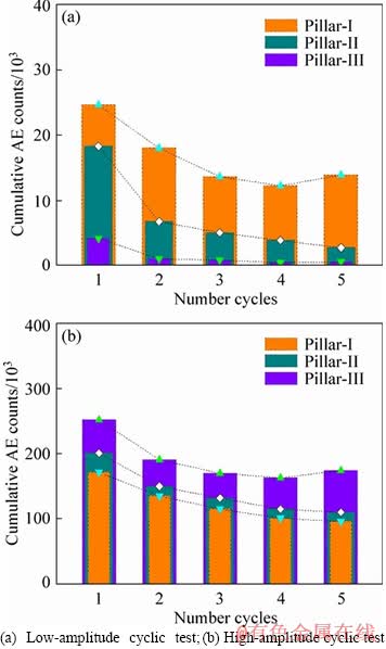
Figure 9 Variation of cumulative AE counts during cyclic loading phase:
3.4 Influence analysis of bearing capacity
Through comparing the axial deformation and AE characteristics during cyclic loading phase, it can be concluded that the high-amplitude obviously aggravates the internal damage of each pillar. After cyclic loading phase, specimens were compressed until failure. The peak loads of specimens in different groups are obtained as listed in Table 2 to evaluate the effect of cyclic loads on the overall bearing capacity of multi-pillar system. Figure 10 further illustrates the average peak load of multi-pillar system and the standard deviation. The average peak load of triple-pillar specimens without pre-cyclic loading is 929.27 kN. However, those subjected to pre-cyclic loading with the amplitude of 200 and 400 kN are 950.92 and 784.34 kN respectively, which increases by 2.33% and decreases by 15.59%, respectively.
Table 2 Experimental results of triple-pillar specimens in different loading schemes
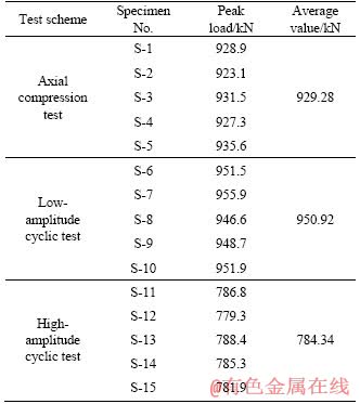
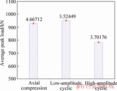
Figure 10 Average peak load and standard deviation for specimens of different groups
Figure 11 depicts load-displacement curves after cyclic loading. Compared with the axial compression test, the slope of load-displacement curve during the pre-peak stage obviously decreases in the high-amplitude cyclic test. This result may be due to that high-amplitude cyclic loads weaken the bearing capacity and stiffness of pillar system and make it more vulnerable to be brittle. On the contrary, after the low-amplitude cyclic loads, both the pre-peak bearing capacity and the post-peak ductility of the pillar system increase due to the compaction of initial defects during the cyclic loading stage.
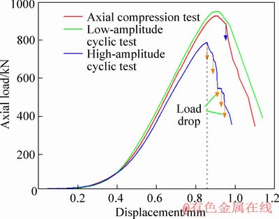
Figure 11 Load versus displacement curves of different testing schemes during axial compression phase
In order to compare with the failure mode in the post-peak stage of axial compression test, the fracture evolution of typical load drop points of each pillar was characterized by the transverse strain fields (��xx) of digital image correlation (DIC). In the axial compression test, the applied load reached the peak (point i-a); macroscopic crack occurred in the lower left corner and in the upper right corner of pillar-I, the surface of pillar-II appeared spalling at the lower left corner; pillar system remained stable, as shown in Figure 12(a). After that, the applied load slowly dropped. At loading point i-b (P=926.5 kN), an obvious localized strain band formed and penetrated on the surface of pillar-I, but the pillar system continued to be stable. It can be inferred that as the condition of pillar-I deteriorates, pillar-II and pillar-III begin to bear more load. At the loading point i-c (P=886.1 kN), a load drop suddenly occurred and severe spalling occurred on both sides of pillar-I, and X-shaped strain localized zones formed on the surfaces of pillar-II and pillar-III. Thereafter, the bearing capacity of pillar system slowly decreased until sudden collapse.
However, in the high-amplitude cyclic test, several abrupt drops in the post-peak stage occurred in a short time. Figure 12(b) shows that, when the load reached 783.3 kN (point ii-a), significant macroscopic crack formed on the right side of pillar-III, and the surface on the left side of the pillar showed obvious spalling. Then, the applied load first appeared to drop significantly. At load drop point ii-b (P=722.8 kN), large-scale spalling and ejection occurred at the upper right of pillar-III, accompanied by loud noises, and a macroscopic shear band formed on the surface. Both pillar-I and pillar-II formed ��X�� shape strain localized zones. Meanwhile, the upper left and lower right corner of pillar-II were severely crushed, giving rise to lots of debris. Spalling and ejection on both sides of pillar-III increased dramatically at point ii-c (P=678.6 kN), the shear band formed at previous load drop point continued to expand, and obvious macroscopic crack band was also formed on the surface of pillar-II with debris ejection. The apparent strain localization band of pillar-I evolved into a transverse transfixion broad band, and the whole pillar system abruptly lost its bearing capacity and collapsed.
Above mentioned results show that the failure process of each pillar can be described as a progressive propagation from the two edges of each pillar to the middle elastic zone, and the strain distribution at both ends of each pillar is symmetrically V-shaped. The extent of key pillar fracture is more serious and violent in the high-amplitude cyclic test, accompanied by the ejection of rock debris and multiple loud noises, indirectly indicating that the post-peak bearing capacity is closely related to the extent of pre-peak cyclic damage.
4 Conclusions
In this work, a series of axial cyclic loading tests with different amplitudes were conducted on triple-pillar marble specimens. Fatigue damage behavior and bearing characteristics have been investigated to understand instability mechanism of underground pillar groups under different cyclic loads. From this study, the main conclusions can be drawn as follows:
1) During cyclic loading phase, high- amplitude cyclic loads resulted in serious irreversible deformation of pillar system, plastic hysteresis loops formed by loading and unloading curves gradually migrated in the direction of increasing displacement, accompanied by energy dissipation.
2) DIC virtual extensometer was applied to calculating axial strain of each pillar during cyclic loading phase. The results show that there was a key pillar producing large axial strain in each pillar system.
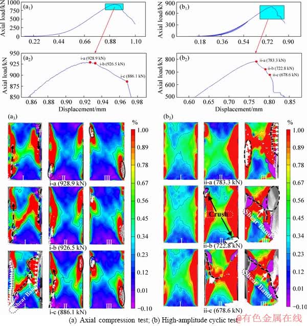
Figure 12 Layout of typical load drop point and corresponding transverse strain field:
3) Due to cyclic damage effect caused by high-amplitude cyclic loads, the key pillar of pillar system suffered damage first, which led to the redistribution of the applied load, and overload was transferred to adjacent pillars.
4) High-amplitude cyclic loads beyond the threshold of damage initiation significantly weakened the bearing capacity of pillar system (load reduction by 15.59%) and made it more vulnerable to be brittle, whereas both the pre-peak bearing capacity and the post-peak ductility of the pillar system increased due to the compaction of initial defects during the cyclic loading stage, indirectly indicating that the peak bearing capacity is closely related to the extent of pre-peak cyclic damage.
References
[1] MALAN D F, NAPIER J A L. The design of stable pillars in the Bushveld Complex mines: A problem solved? [J]. J South African Inst Min Metall, 2011, 111: 821-836. https://repository.up.ac.za/handle/2263/18588.
[2] ESTERHUIZEN G S, DOLINAR D R, ELLENBERGER J L. Pillar and roof span design in stone mines [C]// Dep Heal Hum Serv NIOSH. 2011: 75. https://www.cdc.gov/NIOSH/ Mining/UserFiles/works/pdfs/parsd.pdf.
[3] MARK C, GAUNA M. Preventing roof fall fatalities during pillar recovery: A ground control success story [J]. Int J Min Sci Technol, 2017, 27: 107-113. DOI: 10.1016/j.ijmst.2016. 09.030.
[4] MARTIN C D, MAYBEE W G. The strength of hard-rock pillars [J]. Int J Rock Mech Min Sci, 2000, 37: 1239-1246. DOI:10.1016/S1365-1609(00)00032-0.
[5] LI X, KIM E, WALTON G. A study of rock pillar behaviors in laboratory and in-situ scales using combined finite-discrete element method models [J]. Int J Rock Mech Min Sci, 2019, 118: 21-32. DOI: 10.1016/j.ijrmms.2019. 03.030.
[6] XIA K, CHEN C, ZHOU Y, LIU X, ZHENG Y, PAN Y. Catastrophe instability mechanism of the pillar-roof system in gypsum mines due to the influence of relative humidity [J]. Int J Geomech, 2019, 19: 06019004. DOI: 10.1061/(ASCE) GM.1943-5622.0001378.
[7] CORDING E J, HASHASH Y M A, OH J. Analysis of pillar stability of mined gas storage caverns in shale formations [J]. Eng Geol, 2015, 184: 71-80. DOI: 10.1016/j.enggeo.2014. 11.001.
[8] LI Y H, NAN S Q, ZHAO X D, YANG T H, TANG C A, ZHANG Y B, TAN Z H. Stability of boundary pillars for transition from open pit to underground mining [J]. Chinese J Rock Mech Eng, 2005, 24: 278-283. DOI: 10.1007/s11771- 012-1402-x.
[9] ZHANG Ji-xiong, HUANG P, ZHANG Q, LI M, CHEN Z wei. Stability and control of room mining coal pillars�� Taking room mining coal pillars of solid backfill recovery as an example [J]. Journal of Central South University, 2017, 24: 1121-1132. DOI: 10.1007/s11771-017-3515-8.
[10] WU A X, HUANG M Q, HAN B, WANG Y M, YU S F, MIAO X X. Orthogonal design and numerical simulation of room and pillar configurations in fractured stopes [J]. Journal of Central South University, 2014, 21: 3338-3344. DOI: 10.1007/s11771-014-2307-7.
[11] WANG S, HUANG L, LI X. Analysis of rockburst triggered by hard rock fragmentation using a conical pick under high uniaxial stress [J]. Tunn Undergr Sp Technol, 2020, 96: 103195. DOI: 10.1016/j.tust.2019.103195.
[12] SZWEDZICKI T. Pre- and post-failure ground behaviour: Case studies of surface crown pillar collapse [J]. Int J Rock Mech Min Sci, 1999, 36: 351-359. DOI: 10.1016/S0148- 9062(99)00003-0.
[13] BEREST P, BROUARD B, FEUGA B, KARIMI-JAFARI M. The 1873 collapse of the Saint-Maximilien panel at the Varangeville salt mine [J]. Int J Rock Mech Min Sci, 2008, 45: 1025-1043. DOI: 10.1016/j.ijrmms.2007.10.007.
[14] WANG J A, SHANG X C, MA H T. Investigation of catastrophic ground collapse in Xingtai gypsum mines in China [J]. Int J Rock Mech Min Sci, 2008, 45: 1480-1499. DOI: 10.1016/j.ijrmms.2008.02.012.
[15] WANG S Y, SLOAN S W, HUANG M L, TANG C A. Numerical study of failure mechanism of serial and parallel rock pillars [J]. Rock Mech Rock Eng, 2011, 44: 179-198. DOI: 10.1007/s00603-010-0116-3.
[16] CUI X, GAO Y, YUAN D. Sudden surface collapse disasters caused by shallow partial mining in Datong coalfield, China [J]. Nat Hazards, 2014, 74: 911-929. DOI: 10.1007/s11069-014-1221-5.
[17] ZHOU Z, CHEN L, CAI X, SHEN B, ZHOU J, DU K. Experimental investigation of the progressive failure of multiple pillar�Croof system [J]. Rock Mech Rock Eng, 2018, 51: 1629-1636. DOI: 10.1007/s00603-018-1441-1.
[18] ZHU W, CHEN L, ZHOU Z, SHEN B, XU Y. Failure propagation of pillars and roof in a room and pillar mine induced by longwall mining in the lower seam [J]. Rock Mech Rock Eng, 2019, 52: 1193-1209. DOI: 10.1007/ s00603-018-1630-y.
[19] ZHOU Z, ZHAO Y, CAO W, CHEN L, ZHOU J. Dynamic response of pillar workings induced by sudden pillar recovery [J]. Rock Mech Rock Eng, 2018, 51: 3075-3090. DOI: 10.1007/s00603-018-1505-2.
[20] SINGH R, SINGH A K, MAITI J, MANDAL P K, SINGH R, KUMAR R. An observational approach for assessment of dynamic loading during underground coal pillar extraction [J]. Int J Rock Mech Min Sci, 2011, 48: 794-804. DOI: 10.1016/j.ijrmms.2011.04.003.
[21] SINGH A K, SINGH R, MAITI J, KUMAR R, MANDAL P K. Assessment of mining induced stress development over coal pillars during depillaring [J]. Int J Rock Mech Min Sci, 2011, 48: 805-818. DOI: 10.1016/j.ijrmms.2011.04.004.
[22] KAISER P K, CAI M. Design of rock support system under rockburst condition [J]. J Rock Mech Geotech Eng, 2012, 4: 215-227. DOI: 10.3724/sp.j.1235.2012.00215.
[23] SINGH P K. Blast vibration damage to underground coal mines from adjacent open-pit blasting [J]. Int J Rock Mech Min Sci, 2002, 39: 959-973. DOI: 10.1016/S1365- 1609(02)00098-9.
[24] ZHOU Z, WANG H, CAI X, CHEN L, YUDE E, CHENG R. Damage evolution and failure behavior of post-mainshock damaged rocks under aftershock effects [J]. Energies, 2019, 12: 1-17. DOI: 10.3390/en12234429.
[25] ZHANG X, ZOU Y, HAO H, LI X, MA G, LIU K. Laboratory test on dynamic material properties of annealed float glass [J]. Int J Prot Struct, 2012, 3: 407-430. DOI: 10.1260/2041-4196.3.4.407.
[26] LI C, HAO H, ZHANG X, BI K. Experimental study of precast segmental columns with unbonded tendons under cyclic loading [J]. Adv Struct Eng, 2018, 21: 319-334. DOI: 10.1177/1369433217717119.
[27] ESTERHUIZEN E, DOLINAR D, ELLENBERGER J. Roof span design for underground stone mines [C]// Proc-29th Int Conf Gr Control Mining. ICGCM, 2010: 318-324. https://www.cdc.gov/niosh/mining/UserFiles/works/pdfs/rsdfu.pdf.
[28] MA H, WANG J, WANG Y. Study on mechanics and domino effect of large-scale goaf cave-in [J]. Saf Sci, 2012, 50: 689-694. DOI: 10.1016/j.ssci.2011.08.050.
[29] FUENKAJORN K, PHUEAKPHUM D. Effects of cyclic loading on mechanical properties of Maha Sarakham salt [J]. Eng Geol, 2010, 112: 43-52. DOI: 10.1016/j.enggeo. 2010.01.002.
[30] VOZNESENSKII A S, KRASILOV M N, KUTKIN Y O, TAVOSTIN M N, OSIPOV Y V. Features of interrelations between acoustic quality factor and strength of rock salt during fatigue cyclic loadings [J]. Int J Fatigue, 2017, 97: 70-78. DOI: 10.1016/j.ijfatigue.2016.12.027.
[31] GERANMAYEH VANEGHI R, FERDOSI B, OKOTH A D, KUEK B. Strength degradation of sandstone and granodiorite under uniaxial cyclic loading [J]. J Rock Mech Geotech Eng, 2018, 10: 117-126. DOI: 10.1016/j.jrmge. 2017.09.005.
[32] SONG Z, KONIETZKY H, HERBST M. Bonded-particle model-based simulation of artificial rock subjected to cyclic loading [J]. Acta Geotech, 2019, 14: 955-971. DOI: 10.1007/s11440-018-0723-9.
[33] DANG W, KONIETZKY H, FRUHWIRT T, HERBST M. Cyclic frictional responses of planar joints under cyclic normal load conditions: Laboratory tests and numerical simulations [J]. Rock Mech Rock Eng, 2020, 53: 337-364. DOI: 10.1007/s00603-019-01910-9.
[34] DANG W, KONIETZKY H, CHANG L, FRUHWIRT T. Velocity-frequency-amplitude-dependent frictional resistance of planar joints under dynamic normal load (DNL) conditions [J]. Tunn Undergr Sp Technol, 2018, 79: 27-34. DOI: 10.1016/j.tust.2018.04.038.
[35] SONG H, ZHANG H, KANG Y, HUANG G, FU D, QU C. Damage evolution study of sandstone by cyclic uniaxial test and digital image correlation [J]. Tectonophysics, 2013, 608: 1343-1348. DOI: 10.1016/j.tecto.2013.06.007.
[36] SONG H, ZHANG H, FU D, ZHANG Q. Experimental analysis and characterization of damage evolution in rock under cyclic loading [J]. Int J Rock Mech Min Sci, 2016, 88: 157-164. DOI: 10.1016/j.ijrmms.2016.07.015.
[37] GOODMAN R E. Short notes RICHARD E. Goodman subaudible noise during compression of rocks [J]. Geol Soc Am Bull, 1963: 487-490. DOI: 10.1130/0016-7606.
[38] CAI X, ZHOU Z, LIU K, DU X, ZANG H. Water- weakening effects on the mechanical behavior of different rock types: Phenomena and mechanisms [J]. Appl Sci, 2019, 9: 4450. DOI: 10.3390/app9204450.
[39] ZHOU Z, CHEN L, ZHAO Y, ZHAO T, CAI X, DU X. Experimental and numerical investigation on the bearing and failure mechanism of multiple pillars under overburden [J]. Rock Mech Rock Eng, 2017, 50: 995-1010. DOI: 10.1007/s00603-016-1140-8.
[40] LI D, ZHU Q, ZHOU Z, LI X, RANJITH P G. Fracture analysis of marble specimens with a hole under uniaxial compression by digital image correlation [J]. Eng Fract Mech, 2017, 183: 109-124. DOI: 10.1016/j.engfracmech. 2017.05.035.
[41] ZHOU Z, CAI X, MA D, DU X, CHEN L, WANG H, ZHANG H. Water saturation effects on dynamic fracture behavior of sandstone [J]. Int J Rock Mech Min Sci, 2019, 114: 46-61. DOI: 10.1016/j.ijrmms.2018.12.014.
[42] ZHOU Z, CAI X, LI X, CAO W, DU X. Dynamic response and energy evolution of sandstone under coupled static�Cdynamic compression: Insights from experimental study into deep rock engineering applications [J]. Rock Mech Rock Eng, 2019. DOI: 10.1007/s00603-019-01980-9.
[43] XIE H, JU Y, LI L, PENG R. Energy mechanism of deformation and failure of rock masses [J]. Chinese J Rock Mech Eng, 2008, 27: 1729-1740. DOI: 10.3321/j.issn:1000- 6915.2008.09.001.
[44] SONG D, WANG E, LIU J. Relationship between EMR and dissipated energy of coal rock mass during cyclic loading process [J]. Saf Sci, 2012, 50: 751-760. DOI: 10.1016/j.ssci. 2011.08.039.
[45] LI T, PEI X, WANG D, HUANG R, TANG H. Nonlinear behavior and damage model for fractured rock under cyclic loading based on energy dissipation principle [J]. Eng Fract Mech, 2019, 206: 330-341. DOI: 10.1016/j.engfracmech. 2018.12.010.
[46] PITAWALA S, SOUNTHARARAJAH A, GRENFELL J, BODIN D, KODIKARA J. Experimental characterisation of fatigue damage in foamed bitumen stabilised materials using dissipated energy approach [J]. Constr Build Mater, 2019, 216: 1-10. DOI: 10.1016/j.conbuildmat.2019.04.267.
[47] SONG Z, KONIETZKY H, FRUHWIRT T. Hysteresis energy-based failure indicators for concrete and brittle rocks under the condition of fatigue loading [J]. Int J Fatigue, 2018, 114: 298-310. DOI: 10.1016/j.ijfatigue.2018.06.001.
[48] LEI D, ZHANG P, HE J, BAI P, ZHU F. Fatigue life prediction method of concrete based on energy dissipation [J]. Constr Build Mater, 2017, 145: 419-425. DOI: 10.1016/j.conbuildmat.2017.04.030.
[49] SONG Z, FRUHWIRT T, KONIETZKY H. Characteristics of dissipated energy of concrete subjected to cyclic loading [J]. Constr Build Mater, 2018, 168: 47-60. DOI: 10.1016/j.conbuildmat.2018.02.076.
[50] DATTOMA V, GIANCANE S. Evaluation of energy of fatigue damage into GFRC through digital image correlation and thermography [J]. Compos Part B, 2013, 47: 283-289. DOI: 10.1016/j.compositesb.2012.10.030.
[51] EBERHARDT E, STEAD D, STIMPSON B. Quantifying progressive pre-peak brittle fracture damage in rock during uniaxial compression [J]. Int J Rock Mech Min Sci, 1999, 36: 361-380. DOI: 10.1016/S0148-9062(99)00019-4.
[52] KHAZAEI C, HAZZARD J, CHALATURNYK R. Damage quantification of intact rocks using acoustic emission energies recorded during uniaxial compression test and discrete element modeling [J]. Comput Geotech, 2015, 67: 94-102. DOI: 10.1016/j.compgeo.2015.02.012.
(Edited by YANG Hua)
���ĵ���
�������ϵ�ڲ�ͬѭ���غ��µij������Լ�ƣ�����˻���
ժҪ��Ϊ���о�ѭ���غ������¶������ϵ�ij������Լ�ƣ�����˻����������������������������˲�ͬѭ����ֵ�������о������������似��(AE)������ɢ����(DIC)����������и������������ݻ����ƻ���Ϊ����ʵʱ���ͼ�¼�������˵��¿���Ⱥ�ֱ�ʧ�ȹ��̡��о����������������ʼ������ֵ��ѭ����ֵ�����˶������ϵ�ı��εֿ����������³����������ͺ�������ɢ���ԡ��෴���ͷ�ֵѭ���µĿ�����ԭʼȱ�ݱ�ѹ�����ã���ǰ�������ͷ����չ�Ծ���������������Ȼ������ϵ�ij��������ǰƣ�����˳̶�������ء���������ɢ����������Ʋ����õ�������Ӧ�������ѭ���θ����������˳̶ȣ�ʶ����������ϵ�еĹؼ����ο�����ͬʱ����������ɢ�ߺ���Ӧ�䳡�����˸��������μ��������غɽ����������ݻ����̣��߷�ֵѭ����Ĺؼ��������������Ϊǿ�Һ�������Ϊ���أ���������м����;�������
�ؼ��ʣ��������ϵ��ѭ�����أ�ƣ�����ˣ��������ԣ������䣻����ɢ��
Foundation item: Project(2015CB060200) supported by the National Basic Research Program of China; Project(41772313) supported by the National Natural Science Foundation of China; Project(2017zzts185) supported by the Fundamental Research Funds for the Central Universities, China
Received date: 2019-07-23; Accepted date: 2019-12-09
Corresponding author: WANG Hai-quan, PhD Candidate; Tel: +86-18213488655; E-mail: hq-wang1010@csu.edu.cn; ORCID: 0000- 0001-7176-1251

