

Trans. Nonferrous Met. Soc. China 22(2012) 2000-2006
Electrochemical hydrogen storage characteristics of Ti0.10Zr0.15V0.35Cr0.10Ni0.30-10% LaNi3 composite and its synergetic effect
WANG Yan-zhi1, 2, ZHAO Min-shou1, 2
1. Hebei Key Laboratory of Applied Chemistry, College of Environmental and Chemical Engineering,
Yanshan University, Qinhuangdao 066004, China;
2. State Key Laboratory of Metastable Materials Science and Technology,Yanshan University, Qinhuangdao 066004, China
Received 30 August 2011; accepted 30 September 2011
Abstract: Hydrogen storage composite alloy Ti0.10Zr0.15V0.35Cr0.10Ni0.30�C10% LaNi3 was prepared by two-step arc-melting to improve the electro-catalytic activity and the kinetic performance of Ti-V-based solid solution alloy. The electrochemical properties and synergetic effect of the composite alloy electrode were systematically investigated by using X-ray diffractometry, field emission scanning electron microscopy, energy-dispersive spectrometry, electrochemical impedance spectroscopy and galvanostatic charge/discharge test. It is found that the main phase of the composite alloy is composed of V-based solid solution phase with a BCC structure and C14 Laves phase with hexagonal structure, while the secondary phase is formed in the composite alloy. The comprehensive electrochemical properties of the composite alloy electrode are significantly improved. The activation cycle number, the maximum discharge capacity and the low temperature dischargeability of the composite alloy are 5 cycles, 362.5 mA��h/g and 65.84% at 233 K, respectively. It is suggested that distinct synergetic effect occurs in the activation process, composite process, cyclic process and discharge process at a low or high temperature under different current densities, in the charge�Ctransfer resistance and exchange current density.
Key words: Ti-V-based solid solution; hydrogen storage composite alloy; electrochemical properties; synergetic effect
1 Introduction
The nickel-metal hydride battery still dominates the hybrid electric vehicle (HEV) markets due to both its high rate charge/discharge capability and high reliability, despite that Li-ion battery technology has made great progress in recent years. In the requirements for HEV battery, energy efficiency is strongly affected by the high rate charge and discharge performance. The high rate performance of Ni-MH battery is closely associated with the activation of the active materials and the hydrogen storage alloy [1]. Ti-V-based systems with BCC structure are considered promising third-generation hydrogen storage materials due to their high hydrogen storage capacity of 3% [2,3]. However, these alloys suffer from disadvantages like difficult activation treatment, poor kinetics, large hysteresis, low cyclic stability and high cost [4,5]. Therefore, some novel composites were manufactured for reducing the high cost and improving the overall performance of the alloys [6-10].
It has been proved that the as-prepared LaNi3 alloy was easily activated at room temperature under a hydrogen pressure of 3.3 MPa [11], despite the shortcoming of low hydrogen storage capacity and poor cyclic stability [12]. Recently, It was reported that additional LaNi3 alloy with better electro-catalyst was helpful to decrease the dehydriding peak temperature and improve the kinetic property of Mg-based hydrogen storage alloys [13]. CHU et al[8] reported that the AB3.5- La�CMg-based alloy as a surface modifier not only increased the discharge capacity but also improved the charge�Cdischarge kinetics of composite electrode greatly. LIU et al [9] found that the electrode made of quasicrystal Ti1.4V0.6Ni alloy and conventional AB3 alloy composite holds better high-rate discharge ability than Ti1.4V0.6Ni. Presently, most of composite hydrogen storage materials are obtained by mechanically alloying. However, there are two disadvantages such as long mechanically alloying time and short cycle stability. In addition, phases cannot be joined closely with each other together in the mechanically alloying process, and particle surface is easy to be oxidized and polluted, as well as some impurity is also easy to be introduced into alloy in the processing. In advance, Ti0.10Zr0.15V0.35Cr0.10Ni0.30-LaNi3 composite hydrogen storage alloy was prepared by two-step arc-melting, and influences of LaNi3 content on the microstructure and electrochemical characteristics of the composite alloy were investigated systematically. It was found that overall electrochemical properties of the composite alloy were significantly improved when LaNi3 content was 10%. In this work, electrochemical hydrogen storage characteristics of Ti0.10Zr0.15V0.35Cr0.10Ni0.30-10%LaNi3 composite prepared by two-step arc-melting and its synergetic effect were investigated systematically.
2 Experimental
Ti0.10Zr0.15V0.35Cr0.10Ni0.30 (represented as TVS hereafter) alloy, LaNi3 alloy and TVS-10% LaNi3 composite alloy (represented as COM hereafter) were prepared by arc-melting the constituent elements on a water-cooled copper hearth under an argon atmosphere, respectively. The samples were all inverted and re-melted three times to ensure good homogeneity. The sample alloys were crushed mechanically in air and ground to powder within mortar. The sample powders with a size of 48-75 ��m were used for electrochemical measurements, and those with a size of 38 ��m were used for XRD analysis with Cu Ka radiation on D/Max�CrB X�Cray diffractometer (XRD). The morphology of COM alloy was observed using field emission scanning electron microscopy (FESEM) analysis on XL30 ESEM FEG scanning electron microscope and composition of the phases was analyzed on a Kevex-sigma Level 4 energy-dispersive spectrometer (EDS), respectively.
The electrochemical properties were measured in a standard three-electrode cell consisting of working electrode (the metal hydride electrode), a counter electrode (Ni(OH)2/NiOOH electrode) with excess capacity and a reference electrode (Hg/HgO). The electrolyte in the cell was 6 mol/L KOH solution. The metal hydride electrode was prepared by mixing the alloy powder with carbonyl nickel powder in a mass ratio of 1:5 and cold-pressing the mixture to form pellets under a pressure of 15 MPa with 10 mm in diameter and about 1.5 mm in thickness. The charge/discharge tests were carried out with DC-5 battery testing instrument under computer control. The low temperature dischargeability(LTD) was measured after being fully charged at constant temperature using a low- temperature equipment (WGD701). During the charge/discharge tests, the electrodes were fully charged (the over-charged ratio approximately 30%) at a current density of 60 mA/g, and then discharged to -0.6 V versus Hg/HgO at 60 mA/g.
After the test electrodes were completely activated, the electrochemical impedance spectroscopy(EIS) measurements were conducted at 50% depth of discharge (DOD) using a Solartron 1287 Potentiostat/Galvanostat and a Solartron 1255 frequency response analyzer with Z-POLT software in the frequency range of 0.1 Hz to 1 MHz with an ac amplitude perturbation of 5 mV under open circuit condition. The measurement of electrochemical properties was similar to that described in our previous paper [10].
3 Results and discussion
3.1 Structure characteristics
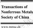
XRD patterns of as-cast COM, TVS and LaNi3 alloys are shown in Fig. 1. It indicates that the matrix phase structure of TVS alloy composing of V�Cbased solid solution phase with a BCC structure and C14 Laves phase with MgZn2-type hexagonal structure has not been changed after LaNi3 alloy is added. However, the secondary phase exhibits as small additional peaks and the PuNi3 phase of LaNi3 alloy cannot be detected in COM alloy. The lattice parameters of the BCC phase and C14 Laves phase in as-prepared composites were calculated using the MDI Jade 5.0 software, and the results are listed in Table 1. It is found that the lattice parameter and cell volume of the BCC phase and C14 Lave phase in COM alloy are both larger than those of TVS alloy, respectively, and the larger cell volume would make for a larger hydrogen storage capacity.
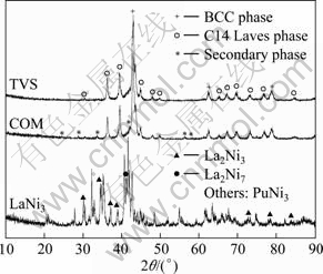
Fig. 1 XRD patterns of as-cast COM, TVS and LaNi3 alloys
Table 1 Lattice parameters of BCC and C14 Laves phase in COM alloy
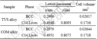
Figure 2 presents the FESEM morphologies of COM alloy. Comparing with the SEM morphology of TVS alloy [14], it is found that COM alloy is composed of V-based solid solution phase with a dendritic shape and a continuous C14 Laves phase with a network shape, and the white lard phase embedded in C14 Laves phase with irregular shape is the secondary phase formed during composite process.
Fig. 2 FESEM morphologies of COM alloy
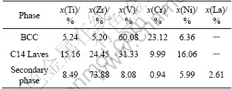
Table 2 summarizes the EDS results obtained from the main phase and the secondary phase of COM alloy. It indicates that the V-based solid solution phase consists of V, Cr and Ni, the C14 Laves phase consists of Zr, Ti, V and Ni, the secondary phase is Zr-rich phase, which shows that the additive LaNi3 alloy is decomposed during composite process, and La can be only detected in the secondary phase of alloy.
Table 2 Phase composition of COM alloy
3.2 Activation performance and synergetic effect
Figure 3 shows the activation performance of COM, TVS and LaNi3 alloy electrode, wherein calculated curve is obtained according to the value measured and composite ratio of TVS and LaNi3 alloy. Firstly, it can be seen that the curve measured is in a position higher than that calculated for COM alloy electrode. It is suggested that distinct synergetic effect exists in activation process.
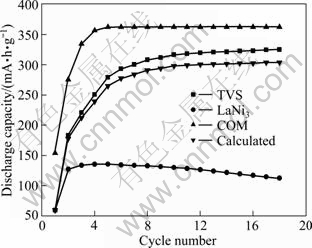
Fig. 3 Activation performance of COM , TVS and LaNi3 alloy electrode
Secondly, it is found that the activation of COM alloy electrode needs only 5 cycles, fewer 13 cycles than that of TVS alloy electrode, which implies that additive LaNi3 alloy is beneficial for improving the electrochemical activity of TVS alloy. Commonly, diffusion through grain boundary having an open structure is easier than that in grain having a perfect lattice [15]. As mentioned above, there are three phases in COM alloy, namely BCC phase, C14 Laves phase and the secondary phase. It is presumed that the phase boundary in COM alloy is more than that in TVS alloy. Furthermore, the secondary phase may become the active sites [16] and pathways for hydrogen diffusion. Thus, the activation performance of COM alloy is evidently better than that of TVS alloy.
3.3 Maximum discharge capacity and synergetic effect
Figure 3 also presents the maximum discharge capacity of COM, TVS and LaNi3 alloy electrode. It is found that the value measured and the value calculated for the maximum discharge capacity of COM alloy electrode are 362.5 and 303.6 mA��h/g, respectively. The results illuminate that the real maximum discharge capacity of COM alloy electrode is not equal to the sum of all the discharge capacity of the constituent alloys, which suggests that synergetic effect appears in the composite process. The maximum discharge capacity of COM increases significantly after compositing with TVS and LaNi3 alloy, which is similar to the composite with MgNi1+x-CNT [17]. This is believed to be caused by an increase in the number of active sites for hydrogen absorption [18]. As mentioned above, the secondary phase in COM alloy may act as active sites.
3.4 Cyclic stability and synergetic effect
The capacity retention (Sn) used to represent the cycling stability can be calculated in the following equation:
Sn=(Cn/Cmax)��100% (1)
where Sn is the capacity retention at n cycles, Cn is the discharge capacity at n cycles and Cmax is the maximum discharge capacity.
Figure 4 indicates the dependence of discharge capacity on cycle number for COM, TVS and LaNi3 alloy electrodes. It is evident that the curve measured is above that calculated for COM alloy electrode, which suggests that distinct synergetic effect appears in cyclic process. In addition, the cyclic stability of COM alloy electrode is superior to that of TVS alloy electrode. For example, S100 of COM alloy electrode is 98.29%, 10.14% higher than that of TVS alloy electrode. It is presumed that additional LaNi3 is helpful for restraining the dissolution of V, Zr and Ti elements in KOH electrolyte and for improving charge-discharge cyclic stability of TVS matrix alloy [10].
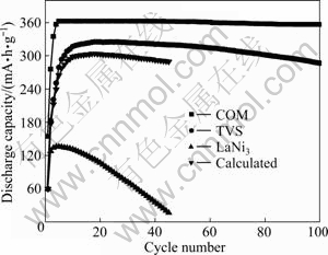
Fig. 4 Dependence of discharge capacity on cycle number for COM , TVS and LaNi3 alloy electrodes
3.5 Temperature effect and synergetic effect
Dischargeability of COM, TVS and LaNi3 alloy electrodes at different temperatures is shown in Fig. 5. The dischargeability at different temperatures is defined as the ratio of the discharge capacity CT at a certain temperature to the discharge capacity C303 at temperature of 303 K. It is found that the curve measured is at a position higher than that calculated in a low temperature range, and the circumstance is opposite in a high temperature range for COM alloy electrode, which suggests that distinct synergetic effect exists in the discharge process at a low or high temperature.
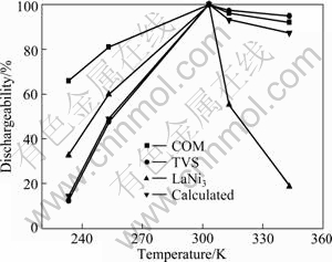
Fig. 5 Dischargeability of COM, TVS and LaNi3 alloy electrodes at different temperatures
It can also be seen that though the high temperature dischargeability (HTD) of COM alloy electrode is a little lower than that of TVS alloy, whereas the low temperature dischargeability (LTD) of COM alloy electrode is remarkably higher than that of TVS alloy electrode. For example, LTD of COM alloy electrode at 233 K is 65.84%, which is about 5.35 times higher that of TVS alloy electrode. This indicates that addition of LaNi3 alloy is beneficial for improving LTD of TVS alloy electrode. It is well known that LTD is mainly controlled by hydrogen diffusion, and hydrogen can diffuse more easily in the bulk of alloys with a larger cell volume and more grain boundaries having an open structure than in grain. Therefore, the increase of cell volume and grain boundaries of composite alloy doubtlessly results in its superior LTD. However, HTD is perhaps attributed to the equilibrium hydrogen pressures of desorption[19]. The hydrogen desorption plateau pressure of COM alloy electrode is higher than that of TVS alloy electrode, and the hydrogen desorption plateau pressure increases with increasing temperature, and thereby the rates of dehydriding of COM alloy and diffusion of hydrogen through COM alloy electrode increase, which inevitably increases the reversible capacity loss and decreases HTD.
3.6 High-rate dischargeability and synergetic effect
High-rate dischargeability (HRD) can be calculated by the following equation:
HRD=(Ci/C60)��100% (2)
where C60 is the discharge capacity at both the charge/discharge current density of 60 mA/g, and Ci is the discharge capacity at certain discharge current density (60-1500 mA/g).
Figure 6 shows high-rate dischargeability as a function of discharge current density for COM, TVS and LaNi3 alloy electrodes. Firstly, it is obvious that HRD of COM alloy electrode is improved remarkably after 10% LaNi3 alloy is added. For example, HRD of COM alloy electrode is about 2.25 times higher that of TVS alloy electrode at a discharge current density of 1500 mA/g. Secondly, it can be seen that the real HRD is markedly higher than that calculated with increasing the discharge current density for COM alloy electrode. For example, the real HRD of COM alloy electrode is 39.54% higher than that calculated at a discharge current density of 1500 mA/g, which suggests that distinct synergetic effect exists in the discharge process at different current densities.
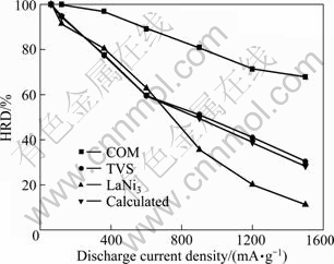
Fig. 6 High-rate dischargeability as function of exchange current density for COM, TVS and LaNi3 alloy electrodes
3.7 Charge�Ctransfer resistance, exchange current density and synergetic effect
Figure 7 presents the electrochemical impedance spectra of COM, TVS and LaNi3 alloy electrodes at 50% DOD and 303 K. On the basis of the model proposed by KURIYAMA et al [20], the charge�Ctransfer resistance Rct is obtained by means of the fitting program Z-view, the exchange current density J0 is calculated by the following equation when overpotential is very small:
J0=(RT/F)(1/Rct) (3)
where R is the gas constant, T is the thermodynamic temperature and F is the Faraday constant. The obtained Rct and J0 are listed in Table 3. On one hand, it shows that the real Rct is 68.57 m�� smaller than that calculated and the real J0 is 258.84 mA/g higher than that calculated for COM alloy electrode, which suggests that distinct synergetic effect appears in the charge�Ctransfer resistance and the exchange current density. According to the concept of synergetic systems of composite proposed by SAVADOGO [18], the characteristics of a synergetic system may be arranged according to the variations of the exchange current density with the parameters of the electrocatalyst (i.e. concentration, electro-chemically active surface area, etc.). Here, the exchange current density is determined with charge�Ctransfer resistance. In addition, XRD and FESEM morphologies indicate that the secondary phase is formed during the compositing process. As a result, it is proposed that the white lard phase is assumably a good electrocatalyst for charge�Ctransfer reaction on the alloy electrodes, which will result in distinct synergetic effect in the charge�C transfer resistance and exchange current density.
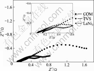
Fig. 7 Electrochemical impedance spectra of COM, TVS and LaNi3 alloy electrodes
Table 3 Electrochemical parameters for TVS, COM and LaNi3 alloy electrode
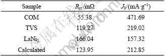
On the other hand, Rct of COM alloy electrode is 63.89 m�� smaller than that of TVS alloy, and J0 of COM alloy electrode is 252.67 mA/g higher than that of TVS alloy, which implies that COM alloy electrode has a higher electrochemical activity than TVS alloy electrode, and then results in its superior HRD.
4 Conclusions
1) The main phase of the solid solution alloy remains unchanged when LaNi3 alloy is added, while the secondary phase is formed in COM alloy.
2) The activation performance, the real maximum discharge capacity, the cyclic stability, LTD and the dynamic performances of COM alloy are remarkably superior to those of TVS alloy.
3) The real maximum discharge capacity of COM alloy electrode is not equal to the sum of all the discharge capacity of the constituent alloys. It is suggested that distinct synergetic effect exists in the compositing process.
4) It is suggested that distinct synergetic effect appears in the activation, cyclic and discharge process at a low or high temperature and at different current densities, in the charge�Ctransfer resistance and exchange current density.
References
[1] GAO F, YANG Y, LIU J, SHAO H. Single-particle investigation on the activation process of a hydrogen storage alloy [J]. International Journal of Hydrogen Energy, 2010, 35(3): 1273-1279.
[2] CHO S W, HAN C S, PARK C N, AKIBA E. Hydrogen storage characteristics of Ti-Zr-Cr-V alloys [J]. Journal of Alloys and Compounds, 1999, 289(1-2): 244-250.
[3] OKADA M, KURIIWA T, TAMURA T, TAKAMURA H, KAMEGAWA A. Ti-V-Cr B.C.C. alloys with high protium content [J]. Journal of Alloys and Compounds, 2002, 330-332: 511-516.
[4] TSUKAHARA M, TAKAHASHI K, MISHIMA T, ISOMURA A, SAKAI T. Vanadium�Cbased solid solution alloys with three�Cdimensional network structure for high capacity metal hydride electrodes [J]. Journal of Alloys and Compounds, 1997, 253-254: 583-586.
[5] KURIYAMA N, TSUKAHARA M, TAKAHASHI K, YOSHINAGA H, TAKESHITA H T, SAKAI T. Deterioration behavior of a multi�Cphase vanadium�Cbased solid solution alloy electrode [J]. Journal of Alloys and Compounds, 2003, 356-357: 738-741.
[6] CHO S W, YOO J H, CHANG H K, KIM W B, KIL D S, AHN J G. Changes in the microstructure and hydrogen storage properties of Ti-Cr-V alloys by ball milling and heat treatment [J]. Journal of Alloys and Compounds, 2011, 509(18): 5545-5550.
[7] QIU S J, CHU H L, ZHANG Y, SUM L X, XU F, CAO Z. The electrochemical performances of Ti-V-based hydrogen storage composite electrodes prepared by ball milling method [J]. International Journal of Hydrogen Energy, 2008, 33(24): 7471-7478.
[8] CHU H L, ZHANG Y, SUN L X, QIU S J, XU F, YUAN H T. The electrochemical properties of Ti0.9Zr0.2Mn1.5Cr0.3V0.3�Cxwt% La0.7Mg0.25Zr0.05Ni2.975Co0.525 (x=0, 5, 10) hydrogen storage composite electrodes [J]. International Journal of Hydrogen Energy, 2007, 32(12): 1898-1904.
[9] LIU W, WANG X, HU W, KAWABE Y, WATADA M, WANG L. Electrochemical performance of TiVNi-Quasicrystal and AB3-Type hydrogen storage alloy composite materials [J]. International Journal of Hydrogen Energy, 2011, 36(1): 616-620.
[10] WANG Y Z, ZHAO M S, LI S C, WANG L M. Structure and electrochemical characteristics of melted composite Ti0.10Zr0.15V0.35Cr0.10Ni0.30�CLaNi5 hydrogen storage alloys [J]. Electrochimica Acta, 2008; 53(27): 831-7837.
[11] CHEN J, TAKESHITA H T, TANAKA H, KURIYAMA N, SAKAI T, UEHARA I, HARUTA M. Hydriding properties of LaNi3and CaNi3 and their substitutes with PuNi3-type structure [J]. Journal of Alloys and Compounds, 2000, 302(1-2): 304-313.
[12] ZHANG X B, YIN W Y, CHAI Y J, ZHAO M S. Structure and electrochemical characteristics of RENi3 alloy [J]. Materials Science and Engineering B, 2005, 117(2): 123-128.
[13] LI Q, XU K D, CHOY K C, LU X G, ZHANG J Y, LIN G W. Synthesis and hydrogenation properties of Mg-3 mol% LaNi3 composite prepared under an external magnetic field [J]. Intermetallics, 2007, 15(1): 61-68.
[14] CHAI Y J, YIN W Y, LI Z L, ZHANG X B, ZHAO M S. Structure and electrochemical characteristics of Ti0.25�CxZrxV0.35Cr0.1Ni0.3 (x=0.05-0.15) alloys [J]. Intermetallics, 2005, 13(11): 1141-1145.
[15] PARK H Y, CHANG I, CHO W I, CHO B W, JANG H, LEE S R, YUN K S. Electrode characteristics of the Cr and La doped AB2�Ctype hydrogen storage alloys [J]. International Journal of Hydrogen Energy, 2001, 26(9): 949-955.
[16] SEO C Y, CHOI S J, CHOI J, PARK C N, LEE J Y. Effect of V and Zr on the electrochemical properties of La-based AB5-type metal hydride electrodes [J]. Journal of Alloys and Compounds, 2003, 351(1-2): 255-263.
[17] GUO Z P, HUANG Z G, KONSTANTINOV K, LIU H K, DOU S X. Electrochemical hydrogen storage properties of nonstoichiometric amorphous MgNi1+x�Ccarbon composites (x=0.05-0.3) [J]. International Journal of Hydrogen Energy, 2006, 31(14): 2032-2039.
[18] SAVADOGO O. On the concept of synergetic systems of composite or modified materials and their electrocatalytic properties: (1) General approach [J]. International Journal of Hydrogen Energy, 2002, 27(2): 157-169.
[19] IWAKURA C, KAJIYA Y, YONEYAMA H, SAKAI T, OGURO K, ISHIKAWA H. Self-discharge mechanism of nickel-hydrogen batteries using metal hydride anodes [J]. Journal of the Electrochemical Society, 1989, 136(5): 1351-1355.
[20] KURIYAMA N, SAKAI T, MIYAMURA H, UEHARA I, ISHIKAEA H, IWASAKI T. Electrochemical impedance and deterioration behavior of metal hydride electrodes [J]. Journal of Alloys and Compounds, 1993, 202(1-2): 183-197.
Ti0.10Zr0.15V0.35Cr0.10Ni0.30-10% LaNi3������ĵ绯ѧ�������Լ�ЭͬЧӦ
����֥1, 2, ������1, 2
1. ��ɽ��ѧ �����뻯ѧ����ѧԺ���ӱ�ʡӦ�û�ѧ�ص�ʵ���ң��ػʵ� 066004��
2. ��ɽ��ѧ ���Ȳ����Ʊ��������ѧ�����ص�ʵ���ң��ػʵ� 066004
ժ Ҫ��Ϊ�˸����ѷ���������Ͻ�ĵ�����ԺͶ���ѧ���ܣ����������绡�������Ʊ����⸴�ϺϽ�Ti0.10Zr0.15V0.35Cr0.10Ni0.30�C10% LaNi3������X-�������䡢������ɨ��羵-���ס��绯ѧ�迹�ͺ�����ŵ���Լ���ϵͳ�о��ô��⸴�ϺϽ�缫�ĵ绯ѧ������ЭͬЧӦ������������ø��ϺϽ��������BCC�ṹ�ķ�����������������ṹ��C14 Laves�࣬�ڸ��Ϲ����������˵ڶ��ࣻ���ϺϽ�缫���ۺϵ绯ѧ���ܽ�ĸ��Ͻ����������ƣ����ϺϽ�缫�Ļ����Ϊ5�ܣ����ŵ�����Ϊ362.5 mA��h/g����233 Kʱ�ŵ�����Ϊ65.84%���ڻ�����ϡ�����ѭ�����ߡ����º߱��ʷŵ�����У��ô��⸴�ϺϽ�缫�ķŵ�����������ЭͬЧӦ���ø��ϺϽ�缫�ĵ��ת�Ƶ���ͽ��������ܶȾ�����ЭͬЧӦ��
�ؼ��ʣ��ѷ��������壻���⸴�ϺϽ𣻵绯ѧ���ܣ�ЭͬЧӦ
(Edited by LI Xiang-qun)
Foundation item: Project (B2011203074) supported by the Natural Science Foundation of Hebei Province, China; Project (201101A129) supported by the Technology Research and Development Program of Qinhuangdao, Hebei Province, China
Corresponding author: WANG Yan-zhi; Tel: +86-335-8061569; E-mail: hhwyz@ysu.edu.cn
DOI: 10.1016/S1003-6326(11)61420-9

