Shift scheduling strategy development for parallel hybrid construction vehicles
��Դ�ڿ������ϴ�ѧѧ��(Ӣ�İ�)2019���3��
�������ߣ������� ����Ӱ ��־�� ������
����ҳ�룺587 - 603
Key words��construction vehicle; hybrid electric vehicle; shift scheduling strategy; shift control; neural network
Abstract: The shift scheduling system of the transmission has an important effect on the dynamic and economic performance of hybrid vehicles. In this work, shift scheduling strategies are developed for parallel hybrid construction vehicles. The effect of power distribution and direction on shift characteristics of the parallel hybrid vehicle with operating loads is evaluated, which must be considered for optimal shift control. A power distribution factor is defined to accurately describe the power distribution and direction in various parallel hybrid systems. This paper proposes a Levenberg-Marquardt algorithm optimized neural network shift scheduling strategy. The methodology contains two objective functions, it is a dynamic combination of a dynamic shift schedule for optimal vehicle acceleration, and an energy-efficient shift schedule for optimal powertrain efficiency. The study is performed on a test bench under typical operating conditions of a wheel loader. The experimental results show that the proposed strategies offer effective and competitive shift performance.
Cite this article as: LI Tian-yu, LIU Hui-ying, ZHANG Zhi-wen, DING Dao-lin. Shift scheduling strategy development for parallel hybrid construction vehicles [J]. Journal of Central South University, 2019, 26(3): 587�C603. DOI: https://doi.org/10.1007/s11771-019-4030-x.

J. Cent. South Univ. (2019) 26: 587-603
DOI: https://doi.org/10.1007/s11771-019-4030-x

LI Tian-yu(������)1, LIU Hui-ying(����Ӱ)2, ZHANG Zhi-wen(��־��)3, DING Dao-lin(������)1
1. School of Mechanical and Aerospace Engineering, Jilin University, Changchun 130025, China;
2. School of Electronics and Information Engineering, Changchun University, Changchun 130022, China;
3. School of Mechanical and Power Engineering, North University of China, Taiyuan 030051, China
 Central South University Press and Springer-Verlag GmbH Germany, part of Springer Nature 2019
Abstract: The shift scheduling system of the transmission has an important effect on the dynamic and economic performance of hybrid vehicles. In this work, shift scheduling strategies are developed for parallel hybrid construction vehicles. The effect of power distribution and direction on shift characteristics of the parallel hybrid vehicle with operating loads is evaluated, which must be considered for optimal shift control. A power distribution factor is defined to accurately describe the power distribution and direction in various parallel hybrid systems. This paper proposes a Levenberg-Marquardt algorithm optimized neural network shift scheduling strategy. The methodology contains two objective functions, it is a dynamic combination of a dynamic shift schedule for optimal vehicle acceleration, and an energy-efficient shift schedule for optimal powertrain efficiency. The study is performed on a test bench under typical operating conditions of a wheel loader. The experimental results show that the proposed strategies offer effective and competitive shift performance.
Key words: construction vehicle; hybrid electric vehicle; shift scheduling strategy; shift control; neural network
Cite this article as: LI Tian-yu, LIU Hui-ying, ZHANG Zhi-wen, DING Dao-lin. Shift scheduling strategy development for parallel hybrid construction vehicles [J]. Journal of Central South University, 2019, 26(3): 587�C603. DOI: https://doi.org/10.1007/s11771-019-4030-x.
1 Introduction
Construction vehicles are important working equipments, which include loaders, bulldozers and scrapers. Compared with passenger vehicles, construction vehicles equip with hydraulic operation system, they usually move and perform work at the same time, and are subject to operating loads. Most construction vehicles equip with a fluid torque converter (FTC) and a power shift transmission. Due to the highly repetitive working characteristics, construction vehicles require frequent and repeated shifts to meet cycle operation requirements. Shift scheduling system for construction vehicles can effectively improve the shift performances and shift quality, which is a meaningful technology for construction vehicles [1]. In recent years, parallel hybrid construction vehicles (PHCVs) have been introduced and developed [2, 3]. The first hybrid construction vehicle was a wheel loader proposed by Hitachi. Volvo proposed a parallel hybrid wheel loader which can save 10% fuel. KAWASAKI proposed a 65Z-2 hybrid wheel loader using an ��HYTCs�� system to replace the FTC, which can save 10% fuel. John Deere introduced a 644K parallel hybrid wheel loader which can improve 20% of the energy saving performance. PHCVs show good system efficiency, they can obviously improve vehicle power performance and fuel economy [3, 4]. Studies have shown that the combination of shift scheduling and hybrid technology can further improve the dynamic performance, energy efficiency, and driving comfort of hybrid electric vehicles [5�C7]. Some PHCVs have begun to use power transmission with shift scheduling system, which is one of the future directions of industrialization.
Shift scheduling strategies are the most important part of the shift scheduling system, which directly affects the shift performance. The shift characteristics of construction vehicles are affected by the operating loads, and the operating loads are usually considered in shift scheduling strategies of construction vehicles [8, 9]. That is also the main difference between shift scheduling strategies of construction vehicles and that of passenger vehicles. Many shift scheduling strategies have been proposed for construction vehicles, which can be divided into two major groups: one is based on specific shift parameters, the other is based on intelligent algorithms. The former mainly indicates two-parameter [10] and three-parameter [11] shift schedule. The simplest two-parameter shift schedule is based on vehicle speed and throttle opening, while it does not take into account the operating loads and is rarely used in construction vehicles. These shift scheduling strategies based on specific shift parameters usually solve specific shift objectives according to a static shift map, which are relatively simple and have good robustness. However, they can hardly get optimal shift control effect. At present, these strategies gradually introduce optimization algorithms to improve shift performance.
Intelligent shift scheduling strategies mainly indicate shift scheduling strategies based on fuzzy logic, neural network, genetic algorithm, etc [12�C14]. Shift scheduling strategies based on fuzzy logic has good robustness, but the control effect is related to design experience, which is hard to offer an optimal solution. Neural network is a widely applicable method for online shift schedule. To a certain extent, the shift scheduling strategies based on neural network are near optimal, consistent and robust. Different optimization methods can be used to train neural network, such as Elman neural network, chaotic neural network, fuzzy neural network, and adaptive neural network. Shift schedule requires robustness, real-time and accuracy. However, the existing neural network shift schedules had a low training convergence speed, which were inapplicable for big data and massive calculation. In this work, we study a high-speed and accurate neural network optimization method for shift schedule, which can meet the real-time control requirements of construction vehicles in complex working environment. Control algorithms based on optimal control theory have been tested for vehicle energy management, such as instantaneous optimization, dynamic programming, Pontryagin��s minimum principle, and model predictive control [15�C19]. The shift control parameter is contained in the optimal problem according to specific cost functions. These methodologies are quite complex, and sometimes the shift decision is involved in the vehicle energy management strategy. They basically need large computation during optimization solution process. Therefore, they have poor real-time performance and hardly can be utilized in practical application. In this work, local optimal method will be introduced to improve shift performance.
Many PHCVs still follow the conventional shift scheduling strategies. To achieve better performance, some manufacturers have introduced PHCVs with the automatic shift function. The Volvo L220F hybrid wheel loader was installed with an automatic shift control device. Based on the shift parameters of vehicle speed and engine speed, the shift control device chose appropriate gear and applied compensation according to the operating conditions [20]. The Caterpillar 966K XE hybrid loader used a continuously variable transmission with the shift scheduling function. Electric motors/ generators and hydraulic pumps/pump-motors have been widely used as auxiliary power components in hybrid vehicles. Studies have shown that the introduction of auxiliary power components changed the vehicle characteristics [21�C23]. Literatures [24, 25] have delved into the evaluation of energy conversion efficiency for different hybrid system topologies based on energy balance equations. These investigations revealed that the power distribution and direction (PDD) has an effect on energy conversion efficiency and fuel economy in different hybrid vehicles. Therefore, control strategies for hybrid vehicles should consider the effect of PDD on the dynamic characteristics of the powertrain in a hybrid system. We have examined the effect of operating load on the shift characteristics in a parallel hybrid loader and found that the shift speed is reduced with increasing operating load [26]. We presented an energy conserving shift schedule and a power shift schedule using the shift parameters of throttle opening, vehicle speed, and operating load factor. In this work, the effect of PDD on the shift characteristics for different combinations of power components will be explored in depth, some competitive shift scheduling strategies will be developed.
To this end, shift scheduling strategies oriented to PHCV applications are developed in this work. The methodology is aimed at analysis of the effect of PDD on shift characteristics, designing shift scheduling strategies. Research on shift schedule of PHCVs is practically significant and has useful applications in construction machinery. The remainder of this paper is organized as follows. The system model of a PHCV is established in Section 2. The effect of PDD on the shift characteristics of a PHCV is discussed in Section 3, and two shift scheduling strategies are proposed based on the shift characteristics. An intelligent shift strategy based on the Levenberg-Marquardt algorithm optimized neural network is presented in Section 4. The proposed shift methodologies are demonstrated by test bench experiments in Section 5. Finally, the conclusions are summarized in Section 6.
2 System model
2.1 Vehicle structure
This section establishes the system model of a typical PHCV. The hybrid powertrain system includes an electric motor/generator and an energy storage device. The energy storage device could be battery modules, supercapacitor modules, or a combination of both. A 5-ton parallel hybrid wheel loader was used as the prototype in this work. Loader is a typical construction vehicle, the research on loader can also be applied to other construction vehicles. The topology and powertrain description of the PHCV are shown in Figure 1. In this topology, the engine and motor are in parallel, and supercapacitor modules serve as energy storage device. The power from the engine and motor is separated into two components. In one component, the power is transferred to the FTC, transmission, drive shafts, main reducer and hub reducer in turn and finally reaches the wheels. In another component, by removing the power consumed by the assistant equipment, the remaining power is transferred to the hydraulic system. The hydraulic system consists of the working pump and steering pump, which are used to drive the bucket operation and steering device, respectively.
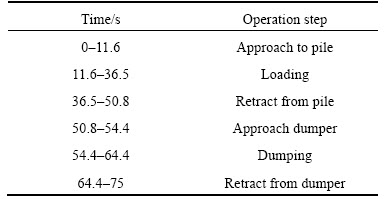
One of the most common operational patterns for wheel loaders is a short loading cycle, which is a V type operation mode. Operating loads spectrums of a 5-ton wheel loader under V type operation mode on native soil are shown in Figure 2. Figure 2(a) is the load torque of transmission, Figure 2(b) is the load pressure of working pump and steering pump. This load spectrum consists of 5 operation cycles, and each operation cycle consists of 6 steps: approach to the pile; loading; retract from the pile; approach the dumper; dumping; retract from the dumper [26, 27]. The time description of the operation steps in the first operation cycle is listed in Table 1. Each step commonly has duration of about 10 s, with another about 10 s for filling the bucket. Obviously, the loads change frequently and markedly, the loads at the different working stages are quite different, and have a strong periodicity.
2.2 Vehicle dynamics
Construction vehicles usually move and perform work at the same time. To drive the hydraulic system, the maximum required power could account for nearly 40%�C60% of the rated power of the engine. The outlet pressure of hydraulic pumps is used to describe the operating load of the hydraulic system, which can be converted to the driving torque of the hydraulic system MHS (MHS) as follows.
 (1)
(1)
The dynamic characteristics of the engine are primarily affected by the inertia and friction losses of the crankshaft and other rotating components. The steady-state driving torque of the engine is revised, and the dynamics formula is applied as follow. A static model was established for motors, and the torque balance formula is shown below.
 (2)
(2)
 (3)
(3)
PHCVs usually equip FTC with the structure of a single turbine and three elements without a lock-up function. The original characteristic curves mentioned in Ref. [28] are used to describe its performance, and the mathematical model is given as follows. According to the bench test data, the original characteristic curves of a YJ355 FTC can be obtained as shown in Figure 3.
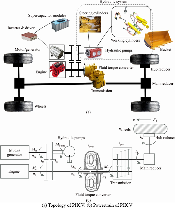
Figure 1 Topology and powertrain description of PHCV:
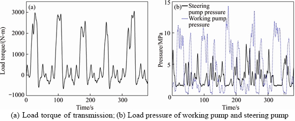
Figure 2 Operating load spectrums of a wheel loader under V type operation mode:
Table 1 Time description of operation steps
 (4)
(4)
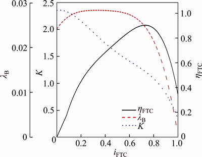
Figure 3 Original characteristic curves of a YJ355 FTC
The driving force of the vehicle is related to various resistances, including rolling resistance Ff, gradient resistance Fw, air resistance Fs, and acceleration resistance Fa. The dynamic balance formulas of parallel hybrid loader are given as follows.
 (5)
(5)
 (6)
(6)
2.3 Joint working characteristics
When the engine, motor, pumps, and FTC work together, they become a coupling compound. It needs to deeply analyze the joint working characteristics of PHCVs, which could directly affect the vehicle performance. The joint working characteristics consist of input characteristics and output characteristics [29]. The former is the variation characteristics of input torque and rotational speed of the FTC with the speed ratio of the FTC. The latter is relationships of out torque and out rotational speed of FTC with the rotational speed of engine. Then, the input characteristics of a parallel hybrid loader can be calculated by formula (7), and the joint working constraints are shown in formula (8). The output characteristics of PHCV are calculated by formula (9).
 (7)
(7)
 (8)
(8)
 (9)
(9)
Furthermore, for a parallel hybrid system with multi motors/generators and hydraulic pumps/ pump-motors, the joint working characteristics could be obtained through similar method. It is easy to deduce the joint working characteristics of a parallel hybrid system with k hydraulic pumps/ pump-motors and l motors/generators. The input characteristics are the same as formulas (7) and (8), while the input torque is different as shown in formula (10). The driving torque of generator and pump is positive, the generating torque of motor and pump-motor is negative in formula (10).
 (10)
(10)
It could find that the joint work of the engine, motors, pumps, and FTC has a close relationship with motors/generators and hydraulic pumps/ pump-motors. In a parallel hybrid system, the output of FTC is evidently affected by the operating loads from the hydraulic system, and the working conditions from motors/generators. Thus, the power distribution and direction of various parallel hybrid systems must be considered in shift scheduling strategies.
3 Shift scheduling strategy development
3.1 Power distribution factor
Literatures [29, 30] show that the operating loads have a direct impact on the shift characteristics. In a parallel hybrid system, operating loads, electric motors/generators, and hydraulic pumps/pump-motors could affect the vehicle dynamic performance and fuel economy. To accurately describe the PDD in various types of parallel hybrid vehicles, a power distribution factor (PDF) was proposed and defined as: the consumed or inputted torque by the electric motors/generators, plus the consumed or inputted torque by the hydraulic pumps/pump-motors, the PDF is the ratio between their sum and the rated torque of the engine. For a hybrid system with k hydraulic pumps/pump-motors and l motors/generators, the PDF can be calculated as below:
 (11)
(11)
The inputted torque is negative and the consumed torque is positive in formula (11). The working ranges of the motors and hydraulic pump/pump-motors are both limited, so the PDF is theoretically bounded, and it can be positive, negative or zero.
The definition of the PDF is scientific and reasonable. First, this factor can reasonably and accurately describe the effect of the operating load and torque of motor/generator and hydraulic pump/ pump-motor on shift characteristics. Secondly, this factor can be easily and accurately measured or calculated:
1) Motoring/generating torque of a motor/ generator. The parameters of some advanced motors/generators can be obtained by data bus; the rotational speed, voltage, and current of old- fashioned motor/generator can be measured and calculated.
2) Motoring/generating torque of a hydraulic pump/pump-motor. The outlet pressure and rotational speed of a constant rate pump/pump- motor can be detected; the outlet pressure, rotational speed and angle variables of the variable pump/pump-motor can be measured. Then, the torque can be calculated.
3) Working state of the engine. The real-time working parameters of electronic fuel injection (EFI) engine can be read through the controller area network (CAN) bus. The working parameters of some old-fashioned engines can be obtained using throttle opening and rotational speed.
In this paper, the PDF of the PHCV can be calculated as follow.
 (12)
(12)
3.2 Effect of PDF on shift characteristics
From the constraints shown in formulas (7)�C (9), it can be found that �� and MeB have the following relationship.
 (13)
(13)
The driving torque of the engine with different PDFs is used to explore the effect of the PDF on the joint working characteristics, as shown in Figure 4.
These curves are obtained from the joint working characteristics of the PHCV under different PDFs. The curves A in the figure are the working characteristics of the engine at a constant throttle opening degree under different PDFs. With the increase of PDF, additional power is consumed from the engine, and the output of the power source is reduced, which means that the working characteristics of the engine decrease with increasing PDF. The curves C in Figure 4 show MB under different iFTC. The joint working points of the engine, motors, pumps, and FTC are the intersections of curves A and B. As observed from Figure 4, the joint working characteristics of the engine, motors, pumps, and FTC are affected by the PDF. When the PDF is sufficiently large, the joint working points are reduced, which means that the original shift speed of the adjacent gears under the traditional shift schedules will be altered. Thus, the shift speed is affected by the PDF, and the PDF must be introduced into the shift schedules for better control performance.
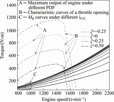
Figure 4 Joint working characteristics
3.3 Dynamic shift schedule
Construction vehicles usually require frequent start, acceleration, deceleration and braking to meet working requirements. To maintain vehicle stability, reduce shift shock, and improve comfort manipulation, a dynamic shift schedule (DSS) was proposed. The objective of DSS is optimal longitudinal acceleration before and after gear shift, which can be described as follows:
 (14)
(14)
 (15)
(15)
Theoretically, DSS displays little shift jerk. DSS introduces �� into the shift decision for optimal vehicle acceleration and drivability, considers the effect of PDD on the shift characteristic.
Multi constraints should be taken into account in practical application, for instance, working requirements, mechanical constraints, joint working constraints, etc. The working torque demand and speed requirement should be firstly ensured. Mechanical constraints include the optimal working range of the engine, motor, pumps, and supercapacitors. The joint working constraints have been shown in formula (8), other restrictions are listed in formula (16).
 (16)
(16)
According to formulas (4), (7), (8) and (11), nT is related to igear and v, and MT is related to ne, v and ��. Substituting these expressions into formula (15), it finds that the shift point is related to ne, v and ��. Vehicle speed of the shift point is related to ne and ��. Therefore, it can solve the DSS at each moment as follows:
Step 1: Read ne, v, ��, gear, an Obtain real-time ne, v, ��, gear, and an at last time
Step 2: an+1*��f (ne, v, ��, gear)Calculate an+1 using formula (15) with current gear
Step 3: an+1*gear+1��f (ne, v, ��, gear+1) Calculate an+1 using formula (15) with adjacent gears
Step 4: an+1*gear�C1��f (ne, v, ��, gear�C1)
Step 5: If (|an+1*gear+1�Can|<| an+1*�Can|)If adjacent gear achieves less ��a, it will be the new gear
Step 6: gear*��gear+1
Step 7: Else if (|an+1*gear�C1�Can|<| an+1*�Can|)
Step 8: gear*��gear�C1
Step 9: ElseOtherwise, maintain the current gear
Step 10: gear*��gear
Step 11: End if
3.4 Energy-efficient shift schedule
In a hybrid system, the efficiency of powertrain attracts special attention. As the existence of the operating loads in PHCV, the consumed/inputted power of the hydraulic pump/motor and motor/generator should be removed from the power source. The efficiency of the powertrain in PHCV can be calculated as follow.

 (17)
(17)
In this work, the coupling of the engine, motors, pumps and FTC is taken as a whole, and an energy-efficient shift schedule (ESS) is proposed. The objective of ESS is optimum efficiency of the powertrain, which is shown below.
 (18)
(18)
The restrictions for ESS are basically the same as DSS, including the constraints in formulas (8), (9) and (16). In ESS, optimum gear is related to ne, v and ��. The optimal gear can be solved according to the objective and restrictions for online practical application.
Most of the existing vehicle energy management control strategies have begun to use optimal control theory. DSS and ESS are essentially optimization methodologies, the shift scheduling strategies proposed in the work can be embedded into the optimal control problems, as one of the optimization objectives.
4 Neural network shift strategy development
4.1 Combination of DSS and ESS
DSS and ESS are two different shift schedules. Independent DSS or ESS encounters difficulty in obtaining good dynamic performance and fuel economy at the same time. Dynamic and economy should both be considered for practical application, and comprehensive shift judgment should be made according to the human-vehicle-road closed loop. This work proposes a simple method that combines DSS and ESS, using vehicle speed to adjust the balance between DSS and ESS. If vehicle speed is low, PHCVs are generally working under a shoveling, heavy transport or heavy load state with poor efficiency, ESS could deliver better vehicle performance at this time. If the vehicle speed is high, PHCVs are usually operating under a light load or walking state. At this time, DSS is preferred to obtain better dynamic. Therefore, shift schedule biases DSS at high speed and biases ESS at low speed. A quantized factor was introduced and defined to normalize the balance in formula (19), and its theoretical range is [0, 1]. The shift speed can be obtained as follows.
 (19)
(19)
4.2 Levenberg-Marquardt algorithm optimized neural network shift schedule
Shift schedule of the construction vehicles requires flexibility, real-time, robustness, and consistency. In this section, a new neural network shift schedule (NNSS) was proposed using a combination of DSS and ESS mentioned above.
The combination contains four variables: ne, v, �� and ��. �� is directly related to the v, so �� is not necessary. Thus, the input variables of the neural network are ne, v, and ��, and the output variables are control gears. For most of the applications of neural network to shift schedules in construction vehicles, one hidden layer appears to be sufficient. Thus, a three-layer neural network is selected. All input parameters are normalized in the range of [�C1, 1], representing the minimum and maximum range of the parameter values. PHCVs usually equip with a four-front-gear transmission, the output variables corresponding to the 1st to 4th gear, and the number of the output node is 1. Thus, the structure of the applied neural network is {3 �C1 2 �C1}, which includes 3 inputs, 12 neurons in the hidden layer, and 1 neuron in the output. A hyperbolic tangent function is implemented for the hidden layer, and a linear function is employed in the output layer. The architecture of the applied neural network is shown in Figure 5.
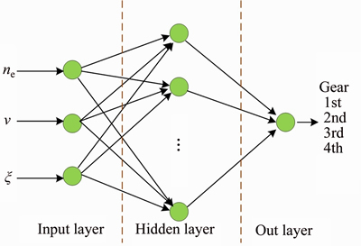
Figure 5 Structure of applied neural network
The adjustment process of the neural network weights is known as training, which is an unconstrained optimization problem. Levenberg- Marquardt (LM) algorithm is known as a nonlinear damped least squares method, and it combines the advantages of the gradient descent method and the Gauss-Newton method, which has good local convergence and global characteristics. Compared with other optimization algorithms, LM has a faster convergence speed with better accuracy [31, 32]. NNSS for construction vehicles needs to deal with big data and massive calculation, LM algorithm is competent for the network learning of the neural network. This paper uses LM algorithm for neural network training. The weights are updated in each iteration of this process. A cost function for training neural network is defined as:
 (20)
(20)
The weights of each layer are updated using LM algorithm. LM algorithm requires the computation of the J matrix at each iteration step and inversion of the JTJ square matrix.

 (21)
(21)
Under a series of different combinations of the ne, v and �� determined conditions, the optimal gear can be resolved. The theoretical ranges of ne, v and �� are all discretized equally, the equidistant points are n1, n2 and n3, respectively. Thus, total combinations will be n1��n2��n3, which could basically cover all working conditions. Finally, these data are randomly divided into two subsets: training (70%) and prediction (30%). The predictive ability of the neural network is the ability to find a satisfactory output that is not included in the training samples. In this section, results obtained by LM neural network will be statistically compared with those given by back propagation (BP) neural network, radial basis function (RBF) neural network, and multiple linear regressions (MLR). The analysis is performed in MATLAB environment, and 10-fold cross validation is performed to evaluate the stability of these algorithms. Seven general statistical parameters are selected to evaluate the prediction ability of the neural network model, namely, root mean square error of prediction (RMSE), relative error of prediction (REP), mean absolute error (MAE), mean squared error (MSE), mean absolute percentage error (MAPE), square of correlation coefficient (R2) and stability (S). Stability is defined in formula (22), which is an evaluation index of algorithm stability. These values for BP, RBF, LM neural network, and MLR are given in Table 2.
 (22)
(22)
Table 2 Statistical parameters
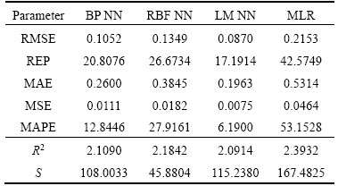
As shown in Table 2, LM neural network has better and more accurate prediction, the superiority of LM neural network in shift control strategies is adequately demonstrated.
4.3 Neural network shift control system
NNSS-based shift control system is a combination of the neural network and control technology. LM algorithm is used to optimize the parameters of the neural network according to the system performance. The structure of the network learning and neural network shift control system are shown in Figure 6.
The basic idea of network learning is to use an adaptive neural network control model, make decision according to the reference object, use LM algorithm to accelerate the convergence speed, finally search out the optimal parameters of the neural network. In Figure 6(a), u(k) is the system input at time k, x(k) is the running state, d(k) is a neural network output with initial parameters, y(k) is the output of training samples. d(k) and y(k) are compared by judging the system error: if d(k) satisfies the error, the parameters of the neural network remain unchanged; Otherwise, the parameters will be updated. Adaptive learning ability of the control structure is strong, and the update speed of the parameters is fast, which can meet the real-time control requirements of construction vehicles in complex working environment.
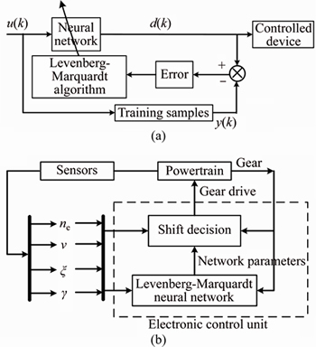
Figure 6 Structure of network learning (a) and neural network shift control system (b)
In Figure 6(b), control parameters can be obtained using the engine speed sensor, vehicle speed sensor, and PDF calculation module. The neural network learning unit continuously collects the vehicle running state, and adjusts the parameters of the neural network. In this way, the neural network can adapt to working environmental changes. After the network adjustment, the parameters are sent to the decision system. Shift cycling was avoided through method of shift delay, which was completed in the decision system. Finally, the electronic control system completes the shift operation.
5 Experimental results
In this section, the proposed shift scheduling strategies were tested in a parallel hybrid loader bench. The bench was tested on four strategies: traditional method, DSS, ESS and NNSS. A traditional three-parameter shift schedule proposed in Ref. [24] was used as the comparison algorithm, which was based on shift parameters of vehicle speed, throttle opening, and load distribution coefficient, with the shift objective of optimal FTC working efficiency. It did not take into account of the effect of PDD on shift characteristics, but consider the effect of operating loads of hydraulic system on shift characteristics.
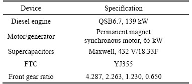
The structure of the bench is illustrated in Figure 7. The engine and motor are structured in parallel, and supercapacitors serve as the energy storage device. An eddy current dynamometer is used to simulate the walking load of the loader, and two proportional relief valves are utilized to simulate the load of the working pump and steering pump. The components parameters of the bench are listed in Table 3.
The typical operating loads of construction vehicles are discussed in Section 2. Construction vehicles have strong periodicity, and the trend of different operating cycles is quite the same. In this section, the first cycle of the operating loads shown in Figure 2 is employed in experiments, the validation of one typical cycle could be convinced. During the experiments, a fuzzy logic based energy management control strategy is used as depicted in Refs. [33, 34]. System demand torque and SOC of the supercapacitors are used as the input parameters in the fuzzy logic controller. Default road slope angle is 0��, the default wind speed is 0, and the minimum shift time interval is 3 s. The experimental results are shown in Figure 8, and the fuel consumptions under different strategies are shown in Table 4.
Figure 8 shows the experimental curves of engine speed, engine torque, motor torque, equivalent vehicle speed, power distribution factor, control gear, gear deviation from that of traditional method, and equivalent vehicle acceleration. At first glance, there is little difference between the experimental curves under different proposed strategies. The dynamometer is an inertial element, which is difficult to simulate the frequent load changes in a short time. Overall, dynamometer could simulate the change trends of the real loads. At the same time, the proposed three strategies all consider the effect of PDD on shift characteristics, and the constraints are the same. Although their objectives have some differences, the experimental results should have the same tendencies. Therefore, the experimental results look similar.
Engine speed in Figure 8(a), engine torque in Figure 8(b), and motor torque in Figure 8(c) under different strategies are quite similar. That is due to the same energy management control strategy. Equivalent vehicle speed in Figure 8(d) is from the transmission output speed that converted to equivalent vehicle speed. According to the load spectrum in Figure 2, the load becomes large at 12 s, which leads to lower vehicle speed. Thus, vehicle speed increases with dwindling loads and higher gears. The four curves in Figure 8(d) have the similar variation tendencies, however, the traditional method has larger variation range. That is because the gear under the traditional method is quite different from the proposed strategies. The maximum speed under the proposed strategies is approximately 8.9 km/h, the maximum speed under the traditional method could reach 17.7 km/h. The PDF in Figure 8(e) is calculated using formula (12), and this parameter changes with the variation of engine torque, pressure of hydraulic pumps, and motor torque. Due to the given loads and energy management control strategy, the change range of PDF is constrained, the maximum PDF is about 0.31, and the minimum PDF is about 0.03.
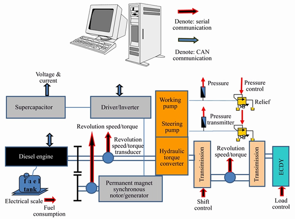
Figure 7 Bench structure
Table 3 Specification of experimental bench
As can be seen in Figures 8(a)�C(h), the proposed strategies shift with the variation of the shift control parameters of engine speed, vehicle speed, and PDF. Shift trends under the proposed strategies are approximately the same, except for certain differences in shifting time, but they all have obvious differences from that of the traditional method. For the proposed three strategies, the initial gear is 2nd, which changes to 3rd at approximately 4 s. As the load becomes large and the vehicle speed rapidly decreases, the vehicle changes gears to 2nd and 1st in turn to meet working requirements. After the heavy load, the vehicle changed gears to 2nd and 3rd in turn. Subsequently, the working load and vehicle speed fluctuate minimally, and the gear does not change. At the end of the experiment,the working load is small, and the vehicle changes to high gear. Overall, gears under proposed strategies are closely relevant to the working load and vehicle speed, and the gears are in line with the actual operating conditions. Overall, the proposed strategies display preferable practicability and robustness. For the traditional method, the initial gear is 2nd, which changes to 1st immediately. That is because the initial vehicle speed is low, and there is hydraulic system pressure, so it has to shift to a lower gear to ensure FTC efficiency. Then, the shift variation tendency is the same as proposed strategies, the gear continuously shifts to 4th, and shifts to 1st in turn during heavy load. Gear variation range under the traditional method is wider than that of the proposed strategies from Figure 8(f). Gear deviation of the proposed strategies from that of the traditional method has some differences from Figure 8(g). The major differences appear at the heavy load period, where the maximum gear deviation could be 2, because of the different shift objectives of these strategies.
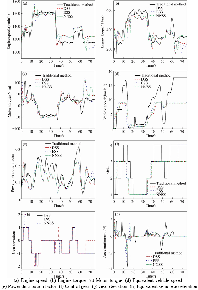
Figure 8 Experimental results:
Table 4 Fuel consumption under different strategies
As observed, the major difference between the proposed three strategies is the control gears during the latter time. Gear under ESS is 4th, but gears under DSS and NNSS are both 3rd. That is because ESS could obtain optimal system efficiency under minimal load conditions, so ESS shifts to 4th at the end stage. For DSS with the objective of optimal vehicle acceleration, its shift decision has a close relationship with the variation of vehicle acceleration. For example, at approximately 4 s and 14 s, DSS shifts with the drastic changes in vehicle acceleration shown in Figures 8(f) and (g). DSS displays an obviously smaller variation in vehicle acceleration than the others, and little shift shock occurrs. The shift decision of ESS could focus on optimal system efficiency under heavy load conditions, where ESS is the first to shift to 1st. Variation of equivalent vehicle acceleration under the traditional method is obviously severer than the proposed strategies, and its maximum is about 3.6 m/s2, the maximum of others is just about 2 m/s2. The traditional method is disappointing for vehicle comfort.
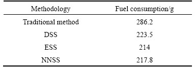
As observed from Figures 8(d), (f), and 8(g), the shift decision under NNSS is generally between that of DSS and ESS, and the tendency is closely linked to vehicle speed. When the engine speed is high, the shift decision pointed towards ESS, but when the engine speed is low, the shift decision is towards DSS. NNSS has preferable robustness and consistency in its performance and combined drivability and energy efficiency. From the equivalent fuel consumption in Table 4, it can be found that ESS saves 4.3% over DSS, and NNSS saves 2.6% over DSS. The proposed three strategies all save quite a lot of fuel than that of the traditional method, which reaches nearly 286.2 g. That is because the traditional method shifts frequently, it is difficult to maintain the stability of powertrain, so its energy saving effect is disappointing. The positive economic influence of the proposed strategies is fully demonstrated.
It should be noted that the dynamometer could not simulate the negative torque of the load spectrum, therefore, certain experimental results are not in agreement with the actual vehicle. However, the main components of the bench are taken from an actual wheel loader, and the experimental results and conclusions can be used as an evaluation standard. Application of the proposed shift scheduling strategies on PHCV shows satisfying performance.
6 Conclusions
Shift scheduling strategies for parallel hybrid construction vehicles are developed in this work. The main contributions are listed as follows.
1) The joint working characteristics of parallel hybrid construction vehicles with operating loads are deduced through dynamic method. Motors/ generators and hydraulic pumps/pump-motors all have a non-ignorable effect on dynamic performance in various parallel hybrid systems.
2) The effect of power distribution and direction on the shift characteristics of parallel hybrid systems is discussed. This effect must be considered in energy management control strategies and shift scheduling strategies.
3) A power distribution factor is defined to accurately describe the power distribution and direction in various parallel hybrid systems. This factor could be introduced into energy management and shift scheduling problems for optimal control.
4) A dynamic shift schedule with the objective of optimal vehicle acceleration, and an energy- efficient shift schedule with the objective of optimal efficiency of the powertrain are proposed. Based on a combination of the previous two schedules, an intelligent shift strategy, Levenberg-Marquardt algorithm optimized neural network shift strategy is presented. This optimization algorithm is competent for the network learning of the neural network for real-time shift scheduling problems.
5) The proposed shift scheduling strategies are tested and verified by bench experiments. The experimental results show that they shift reasonably and accurately with satisfying performance. Thus, the superiority of the proposed strategies is demonstrated.
This research delivers guidance for shift scheduling problems of parallel hybrid construction vehicles. The proposed methods offer a positive alternative for various parallel hybrid vehicles.
Notation
an Acceleration of vehicle at the moment
an+1 Acceleration of vehicle at the next moment
Ce Damping of engine
Cm Damping of motor
d Tanimoto distance
dv/dt Change in vehicle speed over a time step
D Effective diameter of FTC
DSS Dynamic shift schedule
ek Total output error of the n-th sample
E Total error of sample
ESS Energy-efficient shift schedule
f Rolling resistance factor
Fa Acceleration resistance of vehicle
Fd Driving force of vehicle
Ff Rolling resistance of vehicle
Fs Gradient resistance of vehicle
Fw Air resistance of vehicle
FTC Fluid torque converter
PDF Power distribution factor
PHCV Parallel hybrid construction vehicle
g Gravitational acceleration
iB Gear ratio between hydraulic pump and engine
id Gear ratio of main reducer
iFTC Speed ratio of FTC
igear Gear ratio of transmission at n-th gear
iHSi Gear ratio between each hydraulic pump and engine
im Gear ratio between motor and engine
im(n) Ratio between the n-th motor/generator and engine
iw Gear ratio of hub reducer
I Symmetric positive definite matrix for adjustment
Iw Equivalent moment of inertia of wheels
If Moment of inertia of the parts connected to engine
iP(n) Ratio between the n-th pump/pump-motor and engine
ITC Moment of inertia of turbine
J Vehicle shift jerk
Je Equivalent moment of inertia of diesel engine
Jm Equivalent moment of inertia of motor
K Torque ratio of FTC
KA Air resistance factor
LM Levenberg-Marquardt
m Mass of vehicle
MB Torque of FTC��s pump impeller
MBump Torque load of hydraulic system
Me Driving torque of diesel engine
MeB Input torque of FTC��s pump impeller
Med Torque of diesel engine��s shaft
Me max Maximum driving torque of engine
Me min Minimum driving torque of engine
MeN Rated torque of engine
Mi Driving torque of each hydraulic pump
ML Electromagnetic torque of motor
Mm Motoring/generating torque of motor
Mm(n) Motoring/generating torque of n-th motor/generator
Mm max Maximum motoring/generating torque of motor
Mm min Minimum motoring/generating torque of motor
MP(n) Driving torque of n-th pump/pump-motor
MHS Driving torque of hydraulic system
Mreq Required torque of powertrain
MT Torque of FTC��s turbine
nB Speed of FTC��s pump impeller
ne Speed of diesel engine
nm Speed of motor
nT Speed of FTC��s turbine
nTest Number of test samples for cross validation
NNSS Neural network shift schedule
pi Outlet pressure of each hydraulic pump
PDD Power distribution and direction
qi Displacement of each hydraulic pump
r Radius of wheel
Ri Equivalent resistance of ultracapacitor
S Projection area of the vehicle��s windward side
Simi Similarity of Tanimoto distance
SOC State of charge of supercapacitors
SOCmax Maximum working range of SOC
SOCmin Minimum working range of SOC
S Evaluation index of algorithm stability
t Time step duration
tn n time
u Damping factor
U Real time voltage of ultracapacitor
v Vehicle speed
vC Shift speed of the combination of DSS and ESS
vD Shift speed of DSS
vE Shift speed of ESS
vmax Maximum vehicle speed
vw Wind speed
Vmax Maximum working voltage of ultracapacitor
Vmin Minimum working voltage of ultracapacitor
wij Correction weight from input layer to hidden layer
wjk Connection weight from hidden layer to output layer
y Current output value at iteration k
Y1 Output of prediction model
Y2 Output of prediction model
��a Acceleration change before and after shift
�� Quantized factor of DSS and ESS
�� Conversion factor of rotating mass
�� Accuracy requirements for total error of sample
��d Efficiency of main reducer
��e Effective thermal efficiency of engine
��FTC Efficiency of FTC
��gear Efficiency of transmission at n-th gear
��pi Efficiency of each hydraulic pump
��t Efficiency of drive axle
��T Total efficiency of powertrain
��w Efficiency of wheel reducer
�� Slope angle of road
��B Torque factor of pump impeller
�� Learning rate
�� Power distribution factor
�� Fluid density of FTC
��e Angular speed of diesel engine
��m Angular speed of motor
References
[1] OH K, YUN S, KO K, HA S, KIM P, SEO J, YI K. Gear ratio and shift schedule optimization of wheel loader transmission for performance and energy efficiency [J]. Automation in Construction, 2016, 69: 89�C101. DOI: https://doi.org/10.1016/j.autcon.2016.06.004.
[2] LI Tian-yu, LIU Hui-ying, DING Dao-lin. Predictive energy management of fuel cell supercapacitor hybrid construction equipment [J]. Energy, 2018, 149: 718�C729. DOI: https://doi.org/10.1016/j.energy.2018.02.101.
[3] ZENG Xiao-hua, YANG Nan-nan, PENG Yu-jun, ZHANG Ying, WANG Ji-xin. Research on energy saving control strategy of parallel hybrid loader [J]. Automation in Construction, 2014, 38: 100�C108. DOI: https://doi.org/ 10.1016/j.autcon.2013.11.007.
[4] SUN Hui, JING Jun-qing. Research on the system configuration and energy control strategy for parallel hydraulic hybrid loader [J]. Automation in Construction, 2010, 19(2): 213�C220. DOI: https://doi.org/10.1016/j.autcon. 2009.10.006.
[5] SHEN Wen-chen, YU Hui-long, HU Yu-hui, XI Jun-qiang. Optimization of shift schedule for hybrid electric vehicle with automated manual transmission [J]. Energies, 2016, 9(3): 220. DOI: 10.3390/en9030220.
[6] KIM G W. Systematic gear shift model for an automatic- transmission-based parallel hybrid electric vehicle [J]. Proceedings of the Institution of Mechanical Engineers Part D. Journal of Automobile Engineering, 2012, 226(7): 895�C904. DOI: https://doi.org/10.1177/0954407011430276.
[7] SONG M, OH J, KIM J, KIM Y, YI J, KIM Y, KIM H. Development of an electric oil pump control algorithm for an automatic-transmission-based hybrid electric vehicle considering the gear shift characteristics [J]. Proceedings of the Institution of Mechanical Engineers, Part D: Journal of Automobile Engineering, 2014, 228(1): 21�C36. DOI: https://doi.org/10.1177/0954407013497898.
[8] GONG Jie, ZHAO Ding-xuan, HUANG Hai-dong, GONG Wen-bin, CHEN Ying. Study on shift schedule of automatic transmission to improve engineering vehicular efficiency [J]. Chinese Journal of Mechanical Engineering (English Eelition), 2004, 17(1): 124�C126.
[9] YIN Jing-xing, TAN Xiao-feng, LEI Yu-long, GE An-lin. Dynamic shift schedule with 3-parameter based on neural network model of engine [J]. Chinese Journal of Mechanical Engineering, 2005, 41(11): 174�C178. (in Chinese)
[10] GE An-lin. Theory and design of vehicle automatic transmission [M]. Beijing: China Machine Press, 1993. (in Chinese)
[11] WANG Ji-xin, GONG Da-peng, ZHANG Ying-shuang, DENG Ji-ye, SHEN Yong. Modeling of wheel loader powertrain with three-parameters shift strategy and optimization with genetic algorithm [J]. Journal of Jilin University (Engineering Edition), 2011, 41(S1): 27�C33. DOI: 10.13229/j.cnki.jdxbgxb2011.s1.049. (in Chinese)
[12] LI Guang-hui, HU Jian-jun. Modeling and analysis of shift schedule for automatic transmission vehicle based on fuzzy neural network [C]// Intelligent Control and Automation. IEEE, 2010: 4839�C4844. DOI: 10.1109/WCICA.2010. 5554784.
[13] MORTEZA M G, MEHDI M K. An optimal energy management development for various configuration of plug-in and hybrid electric vehicle [J]. Journal of Central South University, 2015, 22(5): 1737�C1747. DOI: 10.1007/s11771-015-2692-6.
[14] CHEN Xue-mei, JIN Min, MIAO Yi-song, ZHANG Qiang. Driving decision-making analysis of car-following for autonomous vehicle under complex urban environment [J]. Journal of Central South University, 2017, 24(6): 1476�C1482. DOI: 10.1007/s11771-017-3551-4.
[15] WANG Wei-da, XIANG Chang-le, LIU Hui, JIA Shi-peng. A model-predictive-control-based power management strategy for a power-split electromechanical transmission [J]. Proceedings of the Institution of Mechanical Engineers, Part D: Journal of Automobile Engineering, 2016, 230(14): 108�C109. DOI: https://doi.org/10.1177/0954407016630911.
[16] LIN Chan-chiao, PENG Huei, GRIZZLE J W, KANG Jun-mo. Power management strategy for a parallel hybrid electric truck [J]. IEEE Transactions on Control Systems Technology, 2004, 11(6): 839�C849. DOI: 10.1109/TCST. 2003.815606.
[17] ENGIN O, ONORI S, WOLLAEGER J, OZGUNER U, RIZZONI G, FILEV D, MICHELINI J, CAIRANO S D. Cloud-based velocity profile optimization for everyday driving: A dynamic-programming-based solution [J]. IEEE Transactions on Intelligent Transportation Systems, 2014, 15(6): 2491�C2505. DOI: 10.1109/TITS.2014.2319812.
[18] ZOU Yuan, LIU Teng, SUN Feng-chun, PENG Huei. Comparative study of dynamic programming and pontryagin��s minimum principle on energy management for a parallel hybrid electric vehicle [J]. Energies, 2013, 6(4): 2305�C2318. DOI: 10.3390/en6042305.
[19] ZHAO Xin-xin, ZHANG Wen-ming, FENG Ya-li, YANG Yao-dong. Optimizing gear shifting strategy for off-road vehicle with dynamic programming [J]. Mathematical Problems in Engineering, 2014(10): 1�C9. DOI: http://dx. doi.org/10.1155/2014/642949.
[20] WANG Ji-xin, YANG Zhi-yu, LIU Shao-kang, ZHANG Qing-yang, HAN Yun-wu. A comprehensive overview of hybrid construction machinery [J]. Advances in Mechanical Engineering, 2016, 8(3). DOI: https://doi.org/10.1177/ 1687814016636809.
[21] CHO S T, JEON S, JO H S, LEE J M, PARK Y I. A development of shift control algorithm for improving the shift characteristics of the automated manual transmission in the hybrid drivetrain [J]. International Journal of Vehicle Design, 2001, 26(5): 469�C495(27). DOI: https://doi.org/10. 1504/IJVD.2001.005219.
[22] TITINA B, TRENC F, KATRA NIK T. Energy conversion efficiency of hybrid electric heavy-duty vehicles operating according to diverse drive cycles [J]. Energy Conversion & Management, 2009, 50(12): 2865�C2878. DOI: https://doi.org/10.1016/j.enconman.2009.06.034
[23] KATRANIK T. Analytical framework for analyzing the energy conversion efficiency of different hybrid electric vehicle topologies [J]. Energy Conversion & Management, 2009, 50(8): 1924�C1938. DOI: https://doi.org/10.1016/ j.enconman.2009.04.016.
[24] ZHAO Ding-xuan, LI Tian-yu, KANG Huai-liang, ZHANG Zhi-wen, LI Mu-fei. Automatic shift technology of hybrid power engineering vehicle [J]. Journal of Jilin University (Engineering Edition), 2014, 44(2): 358�C363. DOI: 10. 13229/j.cnki.jdxbgxb201402013 (in Chinese)
[25] WANG Feng, ZULKEFLI M A M, SUN Zong-xuan, STELSON K A. Energy management strategy for a power-split hydraulic hybrid wheel loader [J]. Proceedings of the Institution of Mechanical Engineers, Part D: Journal of Automobile Engineering, 2016, 230(8), 1105�C1120. DOI: https://doi.org/10.1177/0954407015600899.
[26] SIDDHARTH D, BODIN U, ANDERSSON U. Key challenges in automation of earth- moving machines [J]. Automation in Construction, 2016, 68: 212�C222. DOI: https://doi.org/10.1016/j.autcon.2016.05.009.
[27] LI Tian-yu, LIU Hui-ying, ZHAO Ding-xuan, WANG Li-li. Design and analysis of a fuel cell supercapacitor hybrid construction vehicle [J]. International Journal of Hydrogen Energy, 2016, 41(28): 12307�C12319. DOI: https://doi.org/ 10.1016/j.ijhydene.2016.05.040.
[28] LAREW W B. Fluid clutches and torque converters [M]. Pennsylvania: Chilton Company, 1968.
[29] LI Tian-yu. Study on automatic shift strategy and control method of hybrid construction vehicle [D]. Changchun, China: Jilin University, 2014. (in Chinese)
[30] LV Chang. Intelligent shift schedule based on working conditions of loader [J]. Transactions of the Chinese Society of Agricultural Engineering, 2009, 25(3): 69�C73. (in Chinese)
[31] LERA G, MIGUEL P. Neighborhood based Levenberg-Marquardt algorithm for neural network training [J]. IEEE Transactions on Neural Networks, 2002, 13(5): 1200�C3. DOI: 10.1109/TNN.2002.1031951.
[32] NGIA L S, JONAS S. Efficient training of neural nets for nonlinear adaptive filtering using a recursive Levenberg-Marquardt algorithm [J]. IEEE Transactions on Signal Processing, 2000, 48(7): 1915�C1927. DOI: 10.1109/78.847778.
[33] ZHAO Ding-xuan, ZHANG Zhi-wen, LI Tian-yu, ZHANG Min, DONG Yan. Fuzzy logic control strategy of parallel hybrid power loader [J]. Journal of Jilin University (Engineering Edition), 2014, 44(4): 1004�C1009. DOI: 10.13229/j.cnki.jdxbgxb201404016. (in Chinese)
[34] SCHOUTEN N J, MUTASIM A S, NAIM A K. Fuzzy logic control for parallel hybrid vehicles [J]. IEEE Transactions on Control Systems Technology, 2002, 10(3): 460�C468. DOI: 10.1109/87.998036.
(Edited by FANG Jing-hua)
���ĵ���
����ʽ��϶������̳����������߲��Կ���
ժҪ�������任������ϵͳ�Ի�϶��������Ķ������ܺ;�������������ҪӰ�졣�����о��˲���ʽ��϶������̳����Ļ������߲��ԡ������˶����ֲ�������Բ���ʽ��϶������̳����������Ե�Ӱ�죬�ڻ����Ż������б��뿼������Ӱ�졣������һ���µĶ�������ϵ����ȷ�������ֲ���ʽ��϶���ϵͳ�еĶ����ֲ������������һ�ֻ���Levenberg-Marquardt�㷨�Ż�������Ļ������߲��ԡ��÷�����������Ŀ�꺯�����dz������ٶ����ŵĶ����Ի������ԺͶ���ϵͳЧ�����ŵĽ����Ի������ԵĶ�̬��ϡ�������ʽװ�ػ��ĵ�����ҵ�غɽ�����̨��ʵ�飬����������û�������ʵ������Ч�ġ��������ƵĻ������ܡ�
�ؼ��ʣ����̳�������϶����������������߲��ԣ��������ƣ�������
Foundation item: Project(51805200) supported by the National Natural Science Foundation of China; Project(20170520096JH) supported by the Science and Technology Development Plan of Jilin Province, China; Project(2016YFC0802900) supported by the National Key R&D Program of China
Received date: 2018-03-04; Accepted date: 2018-09-16
Corresponding author: LI Tian-yu, PhD, Lecturer; Tel: +86-13844010051; E-mail: litianyu@jlu.edu.cn; ORCID: 0000-0002-9431-2501
