Configuration design and control of hybrid tracked vehicle with three planetary gear sets
��Դ�ڿ������ϴ�ѧѧ��(Ӣ�İ�)2021���7��
�������ߣ������� ��� ������ ��˧ ���ײ�
����ҳ�룺2105 - 2119
Key words��hybrid tracked vehicles; planetary gear; optimal design; control
Abstract: The hybrid tracked vehicles(HTV) usually adopt series hybrid powertrain with extra steering mechanism, which has relatively low transmission efficiency and reduces the flexibility of structural arrangement. To overcome the disadvantages, a new kind of single-mode powertrain has been proposed. The power-split hybrid powertrain is composed of three planetary gear (PG) sets connected to one engine, left and right track outputs, and three motors. The proposed powertrain can realize steering while going forward by controlling the output torque on each side without extra steering mechanism or steering shaft. Due to the diversity of the connection way between components and planetary gear sets, a rapid configuration design approach is proposed for the design selection of HTV. The automated dynamic modelling method can show the one-to-one correspondence with the selected feasible groups by establishing two characteristic matrices, which is more simple than other researches. The analytically-based method is proposed to classify all possible connection designs into several groups to decrease the searching scope with improved design efficiency. Finally, the optimal control strategy is used to find the design with optimal fuel economy under typical condition of HTV. The case study is implemented by the proposed design approach which demonstrates better design performances compared with the existing series-hybrid HTV.
Cite this article as: LI Rui, FAN Jing-jing, HAN Zheng-da, GUAN Shuai, QIN Zhao-bo. Configuration design and control of hybrid tracked vehicle with three planetary gear sets [J]. Journal of Central South University, 2021, 28(7): 2105-2119. DOI: https://doi.org/10.1007/s11771-021-4756-0.

J. Cent. South Univ. (2021) 28: 2105-2119
DOI: https://doi.org/10.1007/s11771-021-4756-0

LI Rui(���)1, 2, FAN Jing-jing(������)3, HAN Zheng-da(������)1, 2,GUAN Shuai(��˧)3, QIN Zhao-bo(���ײ�)4
1. School of Mechanical Engineering, Beijing Institute of Technology, Beijing 100081, China;
2. China North Vehicle Research Institute, Beijing 100072, China;
3. Intelligent Transportation Key Laboratory, North China University of Technology, Beijing 100144, China;
4. State Key Laboratory of Advanced Design and Manufacturing for Vehicle Body, Hunan University,Changsha 410082, China
 Central South University Press and Springer-Verlag GmbH Germany, part of Springer Nature 2021
Abstract: The hybrid tracked vehicles(HTV) usually adopt series hybrid powertrain with extra steering mechanism, which has relatively low transmission efficiency and reduces the flexibility of structural arrangement. To overcome the disadvantages, a new kind of single-mode powertrain has been proposed. The power-split hybrid powertrain is composed of three planetary gear (PG) sets connected to one engine, left and right track outputs, and three motors. The proposed powertrain can realize steering while going forward by controlling the output torque on each side without extra steering mechanism or steering shaft. Due to the diversity of the connection way between components and planetary gear sets, a rapid configuration design approach is proposed for the design selection of HTV. The automated dynamic modelling method can show the one-to-one correspondence with the selected feasible groups by establishing two characteristic matrices, which is more simple than other researches. The analytically-based method is proposed to classify all possible connection designs into several groups to decrease the searching scope with improved design efficiency. Finally, the optimal control strategy is used to find the design with optimal fuel economy under typical condition of HTV. The case study is implemented by the proposed design approach which demonstrates better design performances compared with the existing series-hybrid HTV.
Key words: hybrid tracked vehicles; planetary gear; optimal design; control
Cite this article as: LI Rui, FAN Jing-jing, HAN Zheng-da, GUAN Shuai, QIN Zhao-bo. Configuration design and control of hybrid tracked vehicle with three planetary gear sets [J]. Journal of Central South University, 2021, 28(7): 2105-2119. DOI: https://doi.org/10.1007/s11771-021-4756-0.
1 Introduction
As the emission and fuel consumption requirements are increasingly strict, hybrid propulsion system for tracked vehicles is being researched and pursued in recent years. Different from the wheeled vehicle, however, the design of hybrid powertrain for tracked vehicles should also take the steering performance into account [1-3]. The power demand is multiple times of that while straight driving when the vehicle is steering, which also increases the design difficulty [4]. Due to the design complexity, research on powertrain of hybrid tracked vehicle is still scanty and incomplete [5]. A dual-motor drive system for heavy-duty tracked vehicle was proposed by ZOU et al [6], which presented the optimal parameter sizing and control simultaneously considering the dynamics of the components. ZHANG et al [7] identified the diesel characteristic in the electric transmission system of tracked vehicle which showed better control results. However, the research mainly adopts the series hybrid system and considers mostly about the straight driving performance. For the series hybrid tracked vehicle, the steering performance depends on the motor power on both sides [5]. Some researches use the gear unit to transfer steering power [6, 8], others may use an extra turning horizontal axis to supply enough power [9, 10]. However, the steering mechanism is separated with the straight driving system, which limits the spatial arrangement.
It is the same with hybrid tracked dozer-type vehicles (HTV), which is one type of the tracked vehicles widely used in construction machinery. HTV is taken as an example to demonstrate the design process. Series hybrid powertrain is also usually adopted in HTV [11]. SCHMIDT [12] established a new kind of dual-motor drive system by adding a variable ratio gear unit between the motors on two sides of track, which may decrease the power demand while steering. Furthermore, the kind of powertrain has also been commercialized. Caterpillar firstly made out the hybrid tracked dozer called D7E that has been proved with good performance using the electric generator, power inverter and propulsion module in the electric drive system to replace the traditional mechanical components. D7E works without the traditional mechanical gearbox and can reduce the fuel economy by 20% compared with D7 type which has the same size while driven by traditional internal combustion engine (ICE) transmission [13]. However, D7E also needs an extra differential steering mechanism with relatively low transmission efficiency.
In order to overcome the aforementioned disadvantages, power-split powertrain with planetary gear (PG) sets shows good potential [14, 15]. The electric powertrain based on PG sets has been used widely on passenger cars, such as Toyota Prius or Chevy Volt. The powertrain based on PG sets is very compact which can realize a continuously variable transmission with large load-carrying capacity [16, 17]. With different components or connections to the node, different kinds of powertrain can be generated, which may be suitable for different types of cars. Many researches have been done based on power-split hybrid vehicles using planetary gear sets which are widely used due to the higher overall efficiency compared with the series or parallel hybrid powertrain. The optimal design of power-split hybrid vehicles was firstly proposed by LIU et al [18, 19] who established a systematic design approach for two planetary gear power-split passenger cars with two modes. ZHANG et al [20, 21] then analyzed different possible configurations using clutches and proposed better designs compared with the existing configurations. However, the research mainly focused on PG sets connected with one drive shaft. Few researches have been done using PG connected with two outputs. YOSHIMURA [22] from Toyota firstly gave a drive system using two PG sets which has two outputs to control the front and rear drive shaft respectively. QIN et al [23] proposed the exhaustive search method of a hybrid power-split drive system based on PG sets. FAN et al [24] proposed a novel control strategy for power-split tracked vehicles. However, the task to find out an optimal and simple design of HTVs rapidly and efficiently is still difficult.
Inspired by the power-split powertrain of the wheeled vehicle, the power-split hybrid HTV with three PG sets connected with two outputs, namely the right and left track, to drive the left and right track independently is proposed. Moreover, we have established the rapid configuration design approach of the single-mode power-split HTV with three PG sets which can overcome the problems brought by the current powertrain and has great potential to design the powertrain for tracked vehicles with high operating efficiency. Specifically, the contributions are summarized as follows.
1) A type of single-mode drive system for hybrid HTV is presented with three PG sets powertrain connected with one engine, two outputs and three motors, which has the same components with the current series hybrid powertrain. The 3PG configuration has been classified into two types, which helps analyze the characteristics more clearly. In addition, the new powertrain can realize functional integration without mode switching.
2) Different from the traditional design method of the planetary gear powertrain for wheeled vehicle, the automated modelling method only takes the single mode of 3DOF design into account, which is more simple and accelerates the calculation speed.
3) The rapid optimal design approach which can choose the configuration among all three PG sets hybrid powertrain according to different design requirements is proposed. The proposed design approach contains the modified automated modelling with two characteristic matrices, analytically-based physical screening, attribute screening, and fuel consumption optimization. The proposed classification helps narrow the search space efficiently.
2 Design objective
Due to the advantages of planetary transmission, power-split tracked dozers can be realized by planetary gear sets. Both the left and right track can be controlled respectively with accurate torque, which is suitable for different kinds of driving conditions. The powertrain doesn��t need to change when transforming from straight driving to steering. The powertrain can also realize central steering and driving backwards. The proposed powertrain has two outputs which is simple and can have better dynamic performance, fuel economy and more compact structure.
In order to control the output torque on both sides respectively, the powertrain based on planetary gear sets needs to have at least two motors with two degrees of freedom. For tracked dozers, extra power should be provided to satisfy some other functions, such as dozer blade. Thus, the powertrain system is designed to have three motors with three degrees of freedom. The power-split tracked dozers consist of one engine, three motors, two separate outputs, namely six components without clutches. Assuming that one node on planetary gear sets only connects with one component, then three planetary gear sets are needed to realize the requirements at least.
The basic structure of the novel powertrain using three planetary gear sets for tracked dozers is shown in Figure 1. The motors can provide both drive and brake power, which depends on the driving conditions. Considering about the possible electric accessory equipment, the powertrain can also provide extra power apart from the demanding driving power.
3 Design approach of power-split hybrid powertrain
Three planetary gear sets (3PG) are used. There can be 45 different connections between these nine nodes in Figure 2. The designs can be outstanding by adding suitable connections. The paper proposes a configuration design approach in order to search the optimal designs rapidly. The whole design approach for the new type of powertrain with three planetary gear sets of hybrid HTVs is shown in Figure 3. Mathematical modelling of the powertrain is conducted first to get the dynamic characteristics matrix which can give a one-to-one correspondence with the configurations and the relationship between rotation speed and operating torque. Then screening is done considering the requirements of tracked vehicle. The optimal design left can gain better performance with the least fuel consumption.
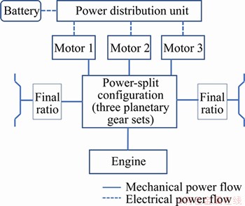
Figure 1 Proposed power-split powertrain with three PG sets
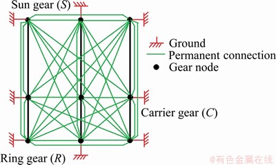
Figure 2 All types of constraints for 3PG set
3.1 Powertrain with three PG sets
For a single planetary gear (PG) set, there are three nodes including sun gear, carrier gear and ring gear, as shown in the Figure 2. The lever diagram is applied to present the mechanical connection of PG sets [25]. The rotation speeds or accelerations should satisfy the following constraint shown in Eq. (1), where S and R are the radii of the sun gear and the ring gear; ��r, ��s and ��c represent the rotation speeds of the ring gear, sun gear and the carrier gear. There are two degrees of freedom (DoF) for a single PG set, which can also be reflected in the dynamics equation as follows.
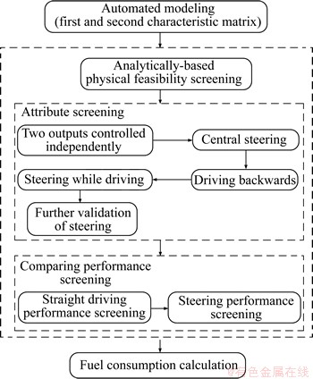
Figure 3 Whole design approach
 (1)
(1)
To realize the design objective, the powertrain needs three DoF, among which two DoFs should ensure that the left and right outputs can be controlled respectively. Three PG sets are used to gain three DoF.
 (2)
(2)
where d represents the system DoF; n represents the number of PG sets; c represents the mechanical constraints in the system. The value of c is calculated to be 3 by Eq. (2), which means the three PG sets are connected with each other by three mechanical connections. It means that three of the constraint line in Figure 2 can be added. The mechanical constraints can be classified into two categories, split constraint: two nodes connected with each other (green line in Figure 2), and brake constraint: one node connected with a brake (red line in Figure 2).
For the powertrain with three PG sets, two split constraints are needed to connect three PG sets with each other to make sure the powertrain can realize the power-split function and the three PG sets are coupled with each other. Thus the remaining constraint can be either split constraint or brake constraint. Actually, the structure of the powertrain can be shown as follows by two sketches with lever diagram without considering the nodes distinction in one PG set and the relative position relationship of the three PG sets, which has summarized all the configuration types into the two kinds of sketches in Figures 4 and 5.

Figure 4 3-power-split PG configuration
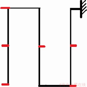
Figure 5 2-power-split PG and 1-power-ratio PG configuration
The six components should be connected to the six red points in the configuration. To show the characteristic of these two kinds of configurations, Figure 4 shows a 3-power-split PG set while Figure 5 a 2-power-slpit and 1-power-ratio PG set. Power-split PG set means that the three nodes are all connected with components and power-ratio means one of the three nodes in a PG set is connected with a brake which makes it a power gear ratio. The proposed classification will improve the screening efficiency in the next step.
Before screening, a fast modelling method should be deduced. To derive the powertrain dynamics of the design object, a kind of configuration in Figure 6 is selected as an example, where eng represents the engine, mg represents motor/generator and output represents the axle connected to the track. Through the relationship between the torque and rotation speed between all components, the dynamics equation can be written as:


 (3)
(3)
where Ri and Si are the radii of the ring gear and sun gear for the ith PG set; Ie, Il, Ir, Img1, Img2 and Img3 represent the rotational inertia of the engine, left output, right output and motors; T and represent the torque and angular acceleration of all components; F1, F2 and F3 represent the internal force of the three PG sets.
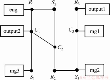
Figure 6 Lever diagram of a three PG sets example
3.2 Automated modelling
Several automated modelling methods have been proposed [21, 23]. However, the methods are time consuming. The paper presents a simpler method for single-mode three PG sets.
The square matrix in Eq. (3) above can be decomposed into four parts as shown in Eqs. (3) and (4), where J is the inertia matrix,  is the angular acceleration of all components and D shows the connections between the components and the PG sets.
 (4)
(4)
Here set D as the first characteristics matrix, which can reflect the one to one correspondence with one unique configuration. For the example above, D matrix can be written as:
 (5)
(5)
The column represents the order of the PG set number and the row represents whether the component is connected in the PG. In this paper, D matrix is defined as the first characteristic matrix. When the D matrix is divided into two parts as follows, the torque relationship between each other can be calculated by Eqs. (6) and (7).
 (6)
(6)
 (7)
(7)
Sometimes, the relationship between torque and rotation speed needs to be defined. In order to show the relationship between the torques and rotation speed, the second characteristic matrix A* is established in Eq. (8).
 (8)
(8)
Assuming that the acceleration performance is not considered, Eq. (1) can be simplified into Eq. (9) as:

 (9)
(9)
where A* is obtained through the following derivation as:


 (10)
(10)
Since D can be written automatically with all kinds of configurations, A* can be easily obtained which can represent the dynamic characteristics for further use. The modelling result is simpler and the proposed method is more suitable for single-mode configuration without clutches.
3.3 Configuration screening
3.3.1 Analytically-based physical feasibility screening
In previous studies, D matrix is usually used to list all possible combinations and to judge whether the configuration is feasible. In our design, if three motors and two outputs are regarded to be different with each other, then the total combination can be listed as follows:
3-power-split configuration

2-power-split and 1-power-ratio configuration

where C and A represent arrangement and combination in mathematics. Without distinguishing the positions of different motors and outputs, the total number can be reduced as:
3-power-split configuration

 =72576
2-power-split and 1-power-ratio configuration


The total number has been decreased to 208656, which is about 1/10. Nevertheless, some physical infeasible configurations still exist among the combinations, such as three motors in a single PG; engine, one output and a brake in a single PG; or two outputs with a brake in a single PG, which cannot ensure enough DoF to control the output torque on both sides of tracks respectively. In order to list all kinds of physical feasible configurations, a forward classification method called analytically-based method is proposed which can also increase the logicality and strengthen the orderliness. It is worth noting that the method is only suitable for single-mode configuration design, which can further accelerate the design time compared to that in Ref. [23].
For a single PG set, there are two kinds of connection ways with the components, namely power-split and power-ratio. Power-split means that all the three nodes on a planetary gear set are connected. Power-ratio means that one node is connected with a brake. All the possible PG sets for the design have been summarized into six ways in Table 1, where �� represents that the component has been connected with one of the nodes of the PG set.
Take B as an example, the PG set has two motors and one engine that are connected to the three nodes. Since there are three PG sets in one configuration and the types of all PG sets belong to the six kinds above, we could further group all configurations by the combination of three PG sets into 3PS configurations and 2PS-1PR configurations in Table 2.
All configurations listed in Table 2 are physical feasible configurations without considering the position of the three PG sets. Thus by analyzing these 23 categories, all physical feasible configurations are selected instead of searching all hundreds of thousands of configurations, which is benefit to the efficiency of the further screening.
In Table 2, A-F denote the configuration categories. Take one of the categories ABC for further explanation. If we consider about the relative position of the three PG sets, six configurations can be obtained, namely ABC, ACB, BAC, BCA, CAB, and CBA. However, the layout plans of ABC and CBA are the same because of the asymmetrical characteristics. It is the same with BAC and CAB, BCA and ACB. Thus actually, for the category ABC in Table 3, 3 small categories can be got by the relative position of the three PG sets. After the analysis above, 30 small categories of 3PS configurations and 27 small categories of 2PS-1PR configurations survive, which are physical feasible. It should also be noted that for each small category, the connections among the three nodes of each PG and the components are not fixed, which means that there should be different connection ways for each small category. However, this can be easily realized as one small category has a one-to-one correspondence kind of characteristic matrix. An example has been given in Figure 7, where a1, a2 and a3 stand for any combinations of the first PG set node coefficients �CR1, �CS1 and R1+S1. It is the same with the second and third PG set.

Instead of an exhaustive exploration approach, the proposed analytically-based method can identify all kinds of different configurations by classifying them into small categories, which reduces the computation cost and helps analyze the characteristics of all kinds of configurations.
Table 1 Connection ways for a single PG
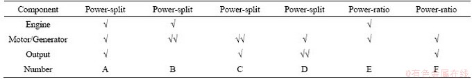
Table 2 All groups of connections
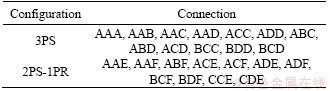
Table 3 Attributes and conditions
3.3.2 Attribute screening
For all physical feasible configurations,attribute screening needs to be done to screen out the designs and satisfy the basic requirements for the hybrid tracked dozers.
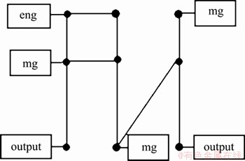
Figure 7 One of small categories ABC and its D matrix
There are four basic requirements listed below to be the main screening attributes. Compared with Ref. [23], central steering is added which is also an essential function for HTV.
1) The torque on both sides of the track can be controlled accurately and independently;
2) While going straightforward, the tracked dozer could steer simultaneously;
3) The tracked dozer could do central steering;
4) The tracked dozer could realize driving backwards.
For all physical feasible configurations, the aforementioned attributes should be verified to screen out the appropriate ones. It can be realized by analyzing the characteristic matrix A*. When a configuration is determined, the D matrix can be obtained and A* can be calculated through Eq. (10). Write all elements of A* in Eq. (11).

 (11)
(11)
The two outputs are of concern to analyze the four attributes, which can be written as:


 (12)
(12)
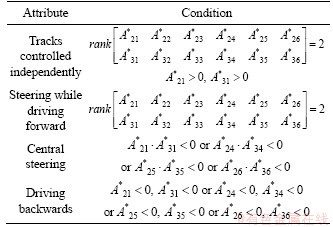
The conditions which satisfy the attributes requirements are listed in Table 3.
For instance, if the tracks on both sides can be controlled respectively, the rotation speed of two outputs should have a different relationship with the torque of all components, namely:
 (13)
(13)
The engine should also provide positive torque to both sides while straightly driving to realize power-split powertrain, which means  and
and  It is the same with the other three conditions.
As the steering performance is rather important for tracked vehicle, and the steering power can sometimes be 15-20 times more than the straight driving power [26], further validation should be done to check the steering attribute. Select the steering radius of 30 m as the index, which is rather easy for a normal tracked dozer. If the configuration cannot satisfy the aforementioned condition, there is no need to follow the left screening process and can be screened out. In this way, the steering characteristics is strengthened and the configuration pool can be narrowed sharply.
The steering torque of each side of track can be found as:

 (14)
(14)
where G means the gravity; f is the rolling friction coefficient; ��max is the steering friction coefficient; L and B are the length and width of grounded track, respectively; R is the steering radius. Through Eq. (7), the maximum torque of two sides of track of our configuration can be calculated as:
 (15)
(15)
The range of torque and rotation speed for components can be calculated, thus the torque range of outputs can be obtained and determine whether the condition can be satisfied. Take the configuration in Figure 5 as an example, the torque range on one side of the track is less than the required maximum steering torque as shown in Figure 8, which means that it cannot satisfy the condition and can be screened out. The left configurations have satisfied the basic steering condition.
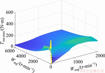
Figure 8 Further validation of steering performance
3.3.3 Performance screening
Except for the attributes above, towing capacity or traction is also an important index while working for a track type dozer. The dozer with larger towing power has more advantages. In this work only the longitudinal force is considered while bulldozing. The maximum drawbar pull under different velocities of different configurations should be calculated. Compared with the design target curve between velocity and drawbar pull, performance screening can be done to find out better configurations.
For tracked vehicles, sometimes the steering performance is also of concern to the users in order to improve the flexibility. Steering radius is the index that can reflect the steering performance. The minimum radius of steering under different velocities should be calculated. Based on the design objective of steering radius, better configurations can be screened out for further use.
3.4 Optimal fuel consumption comparison based on dynamic programming
After verifying the performances above that can satisfy the dozer��s working conditions and the design target, the candidate configurations can be obtained. For the HTV, customers may also focus on the fuel consumption. Designs with better fuel economy can be selected as optimal powertrains. In order to verify the fuel economy of different configurations, the typical working conditions of HTV should be established, which can be used to calculate fuel consumptions.
The driving cycle is established on the basis of a real HTV��s working velocities as shown in Figure 9, which can be used for the following simulations [12]. The working stages in the cycle can be described as follows: 1-4 s traveling stage; 4-16 s soil-cutting stage; 16-31 s soil-transportation stage; 31-33 s unloading soil stage; and 33-50 s no-load stage.
Figure 9 shows the velocity change of all working stages. The pull torque can be calculated using the following equation considering only the longitudinal force. There are two kinds of longitudinal force, namely driving resistance Fd and bulldozing resistance Fb in Eq. (16). The driving resistance contains air resistance, rolling resistance and grade resistance.
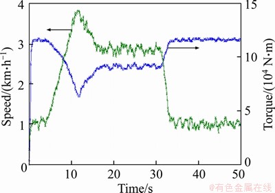
Figure 9 Typical driving cycle of HTV

 (16)
(16)
where Cd is the air resistance coefficient, A is the windward area, v is the velocity, G is the running weight, f is the rolling resistance coefficient, �� is the gradient, kb is the cutting force per unit area, Bc and h is the breadth and cutting depth of dozer blade, respectively, H is the blade height, �� is the soil density, ��1 and ��2 are the rolling resistances of soil-soil and soil-steel, km is the soil filling coefficient, f is the soil angle of gradient, kv and x are the specific resistance and contact area between soil and cutting edge, respectively, and �� is the cutting angle of moldboard. For a determined type of HTV and working cycle, the traction torque can be calculated [26].
Configurations surviving the screening process above should proceed with optimal fuel consumption calculation to find out the optimal one with improving fuel economy. Efficiency-based evaluation real time control strategy (EERCS) is used to solve the globally optimal solution of each configuration to improve the efficiency [23]. EERCS has been verified to be near-optimal compared with DP [27]. EERCS can obtain the control results by maximizing the normalized efficiency. The ��useful�� energy utilized by the system equals the output energy provided by power sources minus the energy losses produced by the motors. The motors are the only components connected to both the electrical and mechanical path, which can be defined as ��bi-pass�� components. Thus, there will be energy losses either from the electrical to the mechanical path (driving motor) or from the mechanical to the electrical path (generator). Now the efficiency of the hybrid mode can be summarized as:


 (17)
(17)
The numerator represents the system ��useful�� energy. The efficiency of the engine is much lower than that of the motor. Without normalizing, the system will always use the electrical energy, resulting in using up the ultracapacitor pack. Thus, each part of the numerator must be normalized with its maximum efficiency. Details can be found in Ref. [23].
4 Case study
The case study here synthesizes the screening process and optimal fuel consumption to find the optimal configurations compared with the current design. As described in the hybrid powertrain, the current powertrain of hybrid HTV is based on series dual-mode-drive hybrid, which has better performance than the conventional engine drive HTV. The optimal configuration was selected by comparing the maximum traction. The fuel consumption of the survived 20 designs is compared with that of the conventional engine-drive HTV.
The first commercial series dual-motor-drive HTV with the model D7E is chosen as comparison to verify the advantages of the power-split HTV with three planetary gear sets. The powertrain of the series hybrid HTV D7E is shown in Figure 10. Differential steering is not considered here.
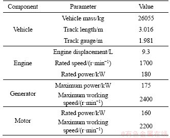
The parameters of D7E are listed in Table 4 for further use [13].
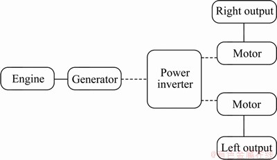
Figure 10 Series dual-motor-drive hybrid dozer
Table 4 Main vehicle parameters of hybrid HTV
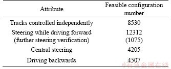
In order to design better configurations using three planetary gear sets, we also adopt one engine and three motors with the same size of the series HTV. The final drive ratio is also the same as D7E. After physical feasible screening in Section 2, totally 12312 configurations are left for further screening. All the dynamics characteristic matrix can be written automatically. After obtaining A*, all candidate configurations should be verified whether the four attributes are satisfied. The feasible ones for each attributes are marked for further use. The number of the feasible ones for each attribute are listed in Table 5.
Table 5 Feasible design numbers for each attribute
When it comes to the performance screening, the towing capacity and the steering radius are chosen to verify the performance of straight driving and steering. As the series hybrid HTV has been chosen as the comparing objective, its performance should be calculated first as reference.
For D7E, the maximum working speed is 11 km/h. From 1 to 11 km/h, every other 1 km/h, the maximum towing traction under different velocities can be calculated based on the characteristic of dual motors on both sides of tracks. As to steering performance, the minimum steering radius under different velocities for D7E can be also obtained according to the driving motors. The integrated performance is shown in Figure 11.
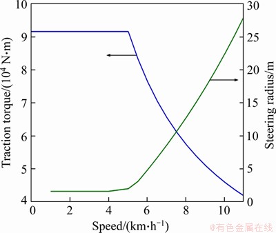
Figure 11 Straight driving and steering performance of D7E
For all the feasible configurations whose tracks on both sides can be controlled independently, the maximum traction can also be calculated similar to the curve shown in Figure 11. The configurations with larger towing capacity are selected for further selection. After verifying the 8530 feasible configurations, 1520 configurations are left which has better towing capacity.
For all the feasible configurations which can steer while driving forward, the minimum steering radius are also calculated for comparison with D7E. It is worth noting that for the configuration with three planetary gear sets and two outputs, as the structure is not symmetrical, the minimum left steering radius and the minimum right steering radius should all be calculated and the smaller one is taken as the minimum radius. After verifying the 1075 feasible configurations, 443 configurations are left which have better steering performance.
After these screening processes, the configurations which have better towing capacity, better steering performance and can realize central steering and driving backwards are found out. Write the characteristic matrix D of all 1520 configurations with better towing capacity, 443 configurations with better steering performance, 4205 configurations which can do central steering, and 4507 configurations which can drive backwards, namely four groups.
If the matrix D of a candidate configuration exists in all four groups, the configuration can be considered for further use. After that, 11 configurations are left which have better integrated performance compared with D7E.
The 11 configurations are all searched to verify the fuel economy. EERCS is used to guarantee the global optimality. Based on the parameters of the D7E and assuming that the contact situation between the soil and the dozer blade remains invariable, the demand torque of the typical working cycle in Figure 5 can be calculated according to Eq. (4). Using the operating torque and speed, simulations can be done. For the surviving 11 configurations, optimal control results are used for comparison of the fuel consumption.
The series dual-motor-drive HTV D7E is used as the comparison. In DP problems, control decisions are given by EERCS through the cost function shown in Eq. (11). For configurations with three planetary gear sets, the states and control variables are listed in Table 6. Without loss of generality, the two outputs on both sides have the same driving torque while straight driving. EERCS ensures that the end value of state of charge (SoC) will almost remain as the initial value.
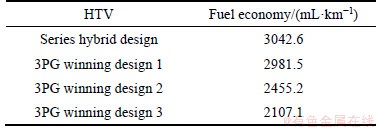
After verifying the fuel economy, 9 configurations show better fuel economy than the series HTV. Three configurations here are taken as examples here, as shown in Table 7. Winning plans 1 and 2 are both 3-power-split PG configuration, which is the BCD and AAB connections respectively. Winning plan 3 is 2PS-1PR configuration which is the BDF connection. It should also be mentioned that the fuel economy of each design has been revised considering the initial and final SOC value [23]. The structures of the 3 winning designs are also given in Figure 12.
Table 6 States and control variables for 3PG configurations
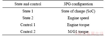
Table 7 States and control variables for 3PG configurations
Taking one winning plan 1 as an example, analyze the performance compared with the existing series hybrid HTV. The performance comparisons of the straight driving and steering are shown in Figures 13-15. The dotted line shows the performance of the series hybrid HTV and the solid line shows the performance of our winning plan. The straight performance is judged by the traction torque. The steering performance is judged by the steering radius with different operating speed. As the winning plan is not symmetrical, the left steering and right steering radius of our plan have both been given in order to show better performance.
Through the comparison results, it can be seen that the winning plan 1 can get larger traction torque under different operating speed. Furthermore, the left steering and right steering performance are both better than the series one. The EERCS control results of the series hybrid HTV and the winning plan 3 are depicted in Figures 16 and 17. For the series plan, as the two motors on both sides have the same operating situation when straight driving, the figure only gives one of the motors performance for reference.
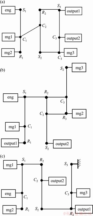
Figure 12 Three winning plans after screening
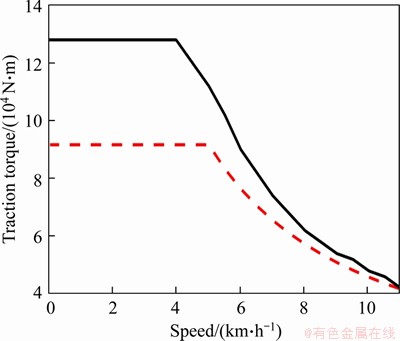
Figure 13 Straight drive performance comparison
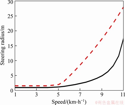
Figure 14 Left-side steering drive performance comparison
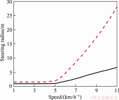
Figure 15 Right-side steering drive performance comparison
It can be concluded that the winning plan 1 has better fuel economy and integrated performance compared with the series hybrid HTV. The design approach can be verified to screen out the feasible designs.
It should be noted that in our research, components sizing and powertrain parameters are certain without optimizing. The main purpose of the study is to demonstrate the design method of hybrid tracked vehicle powertrain. The parameter optimization will be our future work.
5 Conclusions
The paper presents an optimal design approach for the powertrain of power split hybrid tracked dozers with three planetary gear sets without clutches. The approach has three steps: dynamics modelling, physical feasible screening, attributes screening, performance steering and fuel consumption optimization. Two dynamic characteristic matrices have been established to indicate a unique configuration for single-mode configuration, which is more efficient than existing modelling methods. In order to reduce the computational work, the physical feasible screening adopts the analytically-based manual method which can be much clearer. Performance screening takes the straight driving and steering performance into account which can improve the integrated performance. The fuel consumption optimization is validated by comparing the EERCS control results. Main conclusions are given as follow.
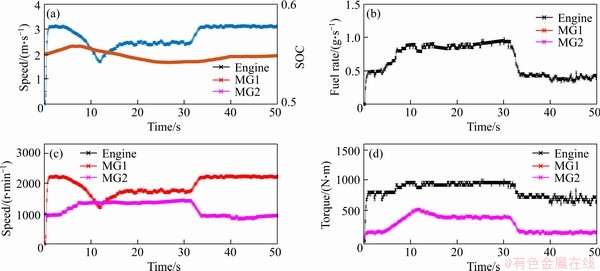
Figure 16 Control results of series hybrid HTV
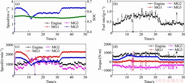
Figure 17 Control results of 3PG winning plan 3
1) A new kind of single-mode powertrain with three planetary gear sets using one engine, three motors and two outputs is proposed. The powertrain has no clutches which is more simple and has advantages compared with current powertrain.
2) The rapid configuration design approach for powertrain of HTV with three planetary gear sets has been established considering the towing capacity, steering performance, central steering performance and the fuel economy. The proposed automated modelling method can generate the model of candidate configurations more efficiently.
3) Based on the case study, the simulation results show that the proposed approach can calculate the optimal designs satisfying the design requirements rapidly.
However, since the proposed design is single-mode, some uncertain operation cases may not be applicative, which needs to be further verified. In addition, some experiments should be done to evaluate the actual performance.
Contributors
LI Rui and FAN Jing-jing wrote the initial draft of the manuscript. HAN Zheng-da established the configuration model and conducted the automated modelling method. GUAN Shuai analyzed the screening and control method. QIN Zhao-bo provided the concept and did the simulation. All authors replied to reviewers�� comments and revised the final version.
Conflict of interest
LI Rui, FAN Jing-jing, HAN Zheng-da, GUAN Shuai and QIN Zhao-bo declare that they have no conflict of interest.
References
[1] KWAK S, KIM T, PARK G. Phase-redundant-based reliable direct AC/AC converter drive for series hybrid off-highway heavy electric vehicles [J]. IEEE Transactions on Vehicular Technology, 2010, 59(6): 2674-2688. DOI: 10.1109/ tvt.2010.2050792.
[2] Alternative fuels and advanced vehicles data center [EB/OL]. 2014. http://www.afdc.energy.gov/data/.
[3] QIN Zhao-bo, LUO Yu-gong, ZHUANG Wei-chao, LI Ke-qiang, PENG Huei. Simultaneous optimization of topology, control and size for multi-mode hybrid tracked vehicles [J]. Applied Energy, 2018, 212: 1627-1641. DOI: 10.1016/ j.apenergy.2017.12.081.
[4] QIN Zhao-bo, LUO Yu-gong, PAN Zi-heng, LI Ke-qiang, PENG Huei. Optimal design of hybrid track-type dozers with two-planetary-gear sets and clutches [C]// International Symposium on Advanced Vehicle Control. CRC Press, 2016: 671-678.
[5] TUAN L A. Modelling and control of tracked vehicles [D]. Sydney: The University of Sydney, 1999.
[6] ZOU Yuan, SUN Feng-chun, HU Xiao-song, GUZZELLA Lino, PENG Huei. Combined optimal sizing and control for a hybrid tracked vehicle [J]. 2012, 5(11): 4697-4710. DOI: 10.3390/en5114697.
[7] ZHANG Yuan, XIE Yong-hai. Modeling, control and analysis of mover for an electric transmission system of tracked vehicle [R]. SAE Technical Paper, 2005.
[8] UMARU S, LIU Shao-jun, HAN Qing-jue. Modeling of miner track system during steering motion [J]. Journal of Central South University, 2015(22): 502-510. DOI: 10.1007/s11771-015-2549-z.
[9] KHALKHALI A, SHOJAEEFARD M H, DAHMARDEH M, SOTOUDEH H. Optimal design and applicability of electric power steering system for automotive platform [J]. Journal of Central South University, 2019, 26(4): 839-851. DOI: 10.1007/s11771-019-4053-3.
[10] BARBAGLI R O, CASTELLI G D. Tracked vehicle with an epicyclic steering differential: US, 5004060 [P]. 1991-04-02.
[11] WANG Hong, SONG Qiang, SUN Feng-chun, ZENG Pu. Parameters matching and simulation on a hybrid power system for electric bulldozer [C]// Proceedings of the 2nd International Conference on Electronic and Mechanical Engineering and Information Technology. 2012: 2137-2142. DOI: 10.2991/emeit.2012.473.
[12] SCHMIDT M R. Two-mode, compound-split, electro-mechanical, vehicular transmission particulary adapted for track-laying vehicles: US, 6491599[P]. 2002-12-10.
[13] CAO Tan-feng. Evaluation of greenhouse gas and criteria emissions from conventional and hybrid off-road equipment [D]. UC Riverside, 2014.
[14] ZHUANG Wei-chao, ZHANG Xiao-wu, PENG Hu-ei, WANG Liang-mo. Simultaneous optimization of topology and component sizes for double planetary gear hybrid powertrains [J]. Energies, 2016, 9(6): 411. DOI: 10.3390/ en9060411.
[15] LI Chiao-ting, PENG Hu-ei. Optimal configuration design for hydraulic split hybrid vehicles [C]// Proceedings of the 2010 American Control Conference. IEEE, 2010: 5812-5817. DOI: 10.1109/ACC.2010.5530490.
[16] HERMANCE D. Toyota hybrid system [C]// 1999 SAE TOPTEC Conference. Albany, NY. 1999: 1-34.
[17] GREWE T M , CONLON B M , HOLMES A G . Defining the general motors 2-Mode hybrid transmission [C]// SAE World Congress & Exhibition. 2007. DOI: 10.4271/2007-01-0273.
[18] LIU Jin-ming. Modeling, configuration and control optimization of power-split hybrid vehicles [D]. Ann Arbor: University of Michigan, 2007.
[19] LIU Jin-ming, PENG Hu-ci. Modeling and control of a power-split hybrid vehicle [J]. IEEE Transactions on Control Systems Technology, 2008, 16(6): 1242-1251.
[20] ZHANG Xiao-wu, LI Sheng-bo, PENG Hu-ei, SUN Jing. Efficient exhaustive search of power-split hybrid powertrains with multiple planetary gears and clutches [J]. Journal of Dynamic Systems, Measurement, and Control, 2015, 137(12): 1-12. DOI: 10.1115/1.4031533.
[21] ZHANG Xiao-wu, PENG Hu-ei, SUN Jing, LI Sheng-bo. Automated modeling and mode screening for exhaustive search of double-planetary-gear power split hybrid powertrains [C]// ASME 2014 Dynamic Systems and Control Conference. American Society of Mechanical Engineers Digital Collection, 2014. DOI: 10.1115/DSCC2014-6028.
[22] YOSHIMURA T. Vehicle power transmission device: US, 8535189 [P]. 2013-09-17.
[23] QIN Zhao-bo, LUO Yu-gong, LI Ke-qiang, PENG Huei. Optimal design of a novel hybrid electric powertrain for tracked vehicles [J]. Energies, 2017, 10(12): 2141. DOI: 10.3390/ en10122141.
[24] FAN Jing-jing, QIN Zhao-bo, LUO Yu-gong, PENG Huei. A novel power management strategy for hybrid off-road vehicles [J]. Control Engineering Practice, 2020, 101: 120-132. DOI: 10.1016/j.conengprac.2020.104452.
[25] BENFORD H L, LEISING M B. The lever analogy: A new tool in transmission analysis [C]// SAE International Congress and Exposition. Detroit, 1981. DOI: 10.4271/810102.
[26] BEKKER M G. Theory of land locomotion [M]. Ann Arbor: The University of Michigan Press, 1956.
[27] BERTSEKAS D P. Dynamic programming and optimal control [M]. Belmont, MA: Athena scientific, 1995.
(Edited by FANG Jing-hua)
���ĵ���
�����������Ǵ����Ļ�϶����Ĵ�����������������
ժҪ����϶����Ĵ�����ͨ�����ô��ж���ת������Ĵ���ʽ�������������Ч�ʺͲ�������Խϵ͡�Ϊ�˷���Щȱ�ݣ����������һ�����͵�ģʽ����ϵͳ������������Ĺ��ʷ�����϶�������ϵͳ�����������Ǵ�����ɣ��ֱ���һ���������������������������������ɡ���ϵͳʡȥ��ת����ᣬ�ܹ�ͨ�����������Ĵ�ת��ʵ���н���ת�����ڲ������������Ǵ��������ӷ�ʽ���������������һ����Դ���ϵͳ���÷���ѡ�͵Ŀ��ٹ�����Ʒ��������У����Զ�����ѧ��ģ������������������ѧ���������ܹ��������в�����ڵ�����ӷ�ʽһһ��Ӧ�����⣬����˻��ڹ��������ɸѡ�����������к�ѡ���÷������з��࣬�������������ģ����������Ч�ʡ�����ڵ������²��ý��������������ԶԺ�ѡ���ͽ������ܺķ����������������������д���ʽ��϶����Ĵ���������ȣ���������Ĺ������ܸ��š�
�ؼ��ʣ���϶����Ĵ��������dz��ִ�����������ƣ�����
Foundation item: Project(CIT&TCD20190304) supported by the Beijing Great Scholars Program, China
Received date: 2020-05-06; Accepted date: 2020-10-11
Corresponding author: FAN Jing-jing, PhD, Engineer; Tel: +86-13466391008; E-mail: jjfan@ncut.edu.cn; ORCID: https://orcid.org/0000-0002-3836- 2758

