J. Cent. South Univ. (2012) 19: 994-1001
DOI: 10.1007/s11771-012-1102-6
Industrial shape detecting system of cold rolling strip
YANG Li-po(杨利坡)1, 2, YU Bing-qiang(于丙强)1, 2, DING Dong(丁栋)1, 2, LIU Hong-min(刘宏民)1, 2
1. National Engineering Research Center for Equipment and Technology of Cold Strip Rolling,Yanshan University, Qinhuangdao 066004, China;
2. State Key Laboratory of Metastable Materials Science and Technology, Yanshan University,Qinhuangdao 066004, China
? Central South University Press and Springer-Verlag Berlin Heidelberg 2012
Abstract: A high-precision shape detecting system of cold rolling strip is developed to meet industrial application, which mainly consists of the shape detecting roller, the collecting ring, the digital signal processing (DSP) shape signal processing board and the shape control model. Based on the shape detecting principle, the shape detecting roller is designed with a new integral structure for improving the precision of shape detecting and avoiding scratching strip surface. Based on the DSP technology, the DSP shape signal processing circuit board is designed and embedded in the shape detecting system for the reliability and stability of shape signal processing. The shape detecting system was successfully used in Angang 1 250 mm HC 6-high reversible cold rolling mill. The precision of shape detecting is 0.2 I and the shape deviation is controlled within 6 I after the close loop shape control is input.
Key words: shape detecting; digital signal processing (DSP) shape signal processing; close loop shape control; cold rolling strip
1 Introduction
The close loop shape control is the most important key technology in cold rolling productions, because the shape (flatness) of cold rolling strip has a significant impact on the quality of follow-up deep-processed products. However, the shape detecting is the core and premise of the close loop shape control [1-4]. In recent years, a variety of structural forms of shape meters and its related mathematical models have been proposed [5-16]. Usually, the shape detecting systems or the shape meters mainly consist of the shape detecting roller, the collecting ring, the AD acquisition card and the shape control model. Affected by temperature, magnetic field, vibration, humidity, corrosion and other severe working conditions, the traditional shape meters are easy to scratch strip surface, or exist signal drift errors and other unexpected problems when used in practical applications. So, the application ranges of the shape meters are very narrow in practical industrial productions, especially for high quality strip.
Based on the shape detecting principle and the shape control theory of cold rolling strip [1-4] and the digital signal processing (DSP) technology [17-19], a high-precision shape detecting system is developed to meet actual industrial application. The integral detecting roller was designed in an innovative way. Its key structural parameters are optimized by finite element method (FEM) for improving the shape signal sensitivity and the shape detecting precision, and avoiding scratching strip surface. Meanwhile, the embedded DSP shape signal processing board is developed for realizing fast signal processing and stable remote transmission of original shape signal.
2 Mechanism analysis of shape defects
In the rolling process, the strips are easy to appear apparent longitudinal extension and lateral flow. Shape defects of cold rolling strip are due to different longitudinal extensions of each lateral strip element [3]. Suppose that a section of strip with a length of L is divided into a number of strip elements, as shown in Fig. 1. When the strip exists some shape defects after rolled, it indicates that elongations of strip elements are inconsistent. Suppose that the elongation difference ?L is between two adjacent strip elements. Among them, the elongation of stretched strip element is negative, which results in tensile stress. And the elongation of compressed strip element is positive, which results in compressive stress.
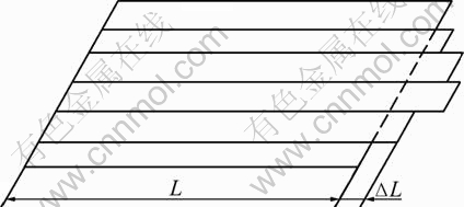
Fig. 1 Extending process drawing of strip elements
Usually, the shape defects can be divided into the apparent (dominant) shape defects and the potential (hidden) shape defects. Under certain conditions, if the internal stress of strip element is less than the critical point of instability, the strip has no apparent warping even without tension. And if the internal stress is large enough and reaches the critical point, the apparent strip warping will occur, which is called the apparent shape defect. Usually, the shape defects are hidden under the action of large tension in the rolling process, which is difficult to be identified by conventional means. So, industrial shape detecting system is very important for accuratly detecting shape defects of strip, recognizing the shape pattern and significantly improving the strip shape quality [11].
3 Principle of shape detecting
As shown in Fig. 2, in the production process of cold rolling strip, the detecting roller generates the original shape signal and transfers signals to embedded DSP shape signal processing board by the collecting ring.
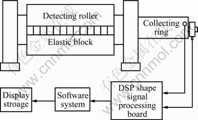
Fig. 2 Diagram of shape detecting system
The detecting roller is usually installed in the export position of cold mill, as shown in Fig. 3. Suppose that the strip wrapping angle around the detecting roller is 2θ, bi is the width of the i-th channel, and hi is the corresponding thickness of strip element.
When the strip tightly wounds on the surface of the shape detecting roller, the radial forces of every channel are real-time detected by piezo-magnetic sensors embeded in the detecting roller, as shown in Fig. 4.
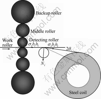
Fig. 3 Force analysis drawing of detecting roller
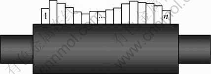
Fig. 4 Radial force distribution of detecting roller
Various radial forces can be converted to tension or residual stress, namely online shape status of cold strips can be obtained [3].
According to the mechanics relations and the geometric conditions, when the radial force Ni of the i-th channel is known, the calculated value  of tension stress is
 (1)
(1)
Suppose that B is the average width of strip, h is the average thickness, T is the total tension measured by the tension meter. Then, the average tension stress  of strip is
 (2)
(2)
In order to quickly calculate the strip shape and display its curve, suppose B=n・bi, hi≈h (i=1, 2, …, n). A simplified formula of tension stress σi can be expressed as
 (3)
(3)
where  means the average radius force of all channels. By Eqs. (2) and (3), the residual stress (stress deviation) ?σi is obtained as
 (4)
(4)
The calculated value  of total tension is obtained by
 (5)
(5)
According to Hook’s law, when the metal has elastic deformation, the stress ?σi is proportional to the elastic deformation  that is
 (6)
(6)
where E is elastic modulus,  is Poisson ratio.
Internationally, usually the basic unit shape I is [3]
 (7)
(7)
where l′ and l are the lengths of the longest element and the shortest element, respectively, and ?l is the length difference between them.
According to Eqs. (6) and (7), the measured shape S can be obtained as
 (8)
(8)
After the actual shape S(y) subtracting the goal shape Sa(y), the online shape deviation ?S is obtained as
?S(yi)=S(yi)-Sa(yi) (9)
Passing ?S to the shape control computer, the real time shape status can be displayed and the strip shape can be controlled by the shape control means of mill at the same time.
4 Integral shape detecting roller
4.1 Features of integral shape detecting roller
The core component of shape detecting system is the detecting roller, which is mainly composed of the main roller body, the elastic block and the Magneto- elastic sensor. The strength and accuracy of signal have direct impact on the precision of the shape detecting system. As shown in Fig. 5, in the assembling process of integral detecting roller, firstly the sensors are fixed in the elastic block which applied pre-pressure to the sensor, and then the blocks are embedded in the symmetrical rectangular slots of the main roller body in turn. The differential circuits are composed of two radial symmetrical sensors for eliminating signal drifting which may be caused by temperature, humidity, vibration, magnetic field and other factors. So, the integral shape detecting roller can significantly improve the shape detecting precision and the anti-interference ability.
The structure of integral shape detecting roller has excellent performance of easy installation and good maintenance, effectively avoiding scratching strip surface. The assembled detecting roller is shown in Fig. 6.
4.2 Internal hole size optimization of elastic block
In the shape detecting process, the elastic block is the most critical component for ensuring steady work of the detecting roller. As shown in Fig. 5, the sensitivity of sensor has a great relationship with the radial position A and the width B of internal hole in the elastic block. The reciprocal pressure difference of sensor is set as the objective function to optimize A and B by ANSYS [19]. Considering the precisions of machining and assembly, finally A and B are determined as 163 and 50 mm, respectively. The optimized structure of detecting roller not only has good mechanical transfer properties, but also has the maximum Mises stress in the safe range. Figure 7 shows a good linear relationship between the radial force of detecting roller and the detecting force of sensor.
4.3 Rotational inertia of detecting roller
As shown in Fig. 8, if the rotational inertia of detecting roller is large, the detecting roller occurs relative sliding with the strip in the acceleration or deceleration process, which leads to scratching the strip surface [19]. Thus, the detecting roller is usually machined as the structure of hollow cylindrical to reduce the rotational inertia.
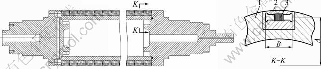
Fig. 5 Internal structure of detecting roller: 1―Main roller body; 2―Elastic block; 3―Magneto-elastic sensor
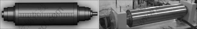
Fig. 6 Shape detecting roller after assembled

Fig. 7 Force transfer curve of detecting roller
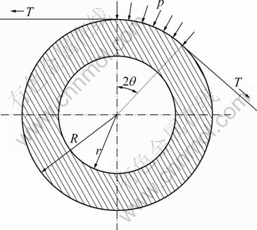
Fig. 8 Force drawing of shape detecting roller
The unit radial pressure p of detecting roller generated by the strip tension T can be equivalent to the total radial force N [7]. By the force balance equation, Eq. (10) is concluded as
 (10)
(10)
If the friction coefficient μ is known, the torque M1 of the detecting roller by friction force f can be expressed as
 (11)
(11)
When the cold mill is working under the maximum acceleration or deceleration, after t, the rolling speed changes from v1 to v2, then the angular acceleration an is
 (12)
(12)
where ω1 and ω2 are angular velocities of detecting roller at different time, respectively.
From Eqs. (10)-(12), the rotational inertia J can be obtained as
 (13)
(13)
where Lb is length of the detecting roller. Then, the inertia moment M2 of detecting roller is
M2=Jan (14)
When M2>M1, the detecting roller will occur relative sliding with the strip. Therefore, M21 should be ensured in the absence of motor-driven situation.
4.4 Collecting ring of detecting roller
The role of collecting ring is achieving static output of original shape signals of high-speed rotation sensor, and its structure significantly affects stability and accuracy of the shape signals. As shown in Fig. 9, a highly integrated collecting ring was developed and mainly composed of the encoder, the signal line, the sub-heads, the brushes, the connectors, the spacing ring, the slip ring, the brush holder, the hollow shaft and other components.
5 Embeded DSP shape signal processing board
As shown in Fig. 10, the DSP shape signal processing board is mainly composed of the lock-in amplifier, the AD converter, the magnetic isolation, the photoelectric isolation, the DSP chip and so on. It can realize rapid processing and remote transmission of shape signals. Multiple isolation measures were used to prevent industrial interference signals of magnetic field, temperature, humidity, vibration and other external factors. Moreover, USB, CAN bus, Ethernet, RS232 and other standard interfaces are equipped to facilitate quick information communication and system expansion. It changes traditional signal processing modes (ISA, PCI and PXI), and achieves miniaturization, integration and networking of the shape signal processing.
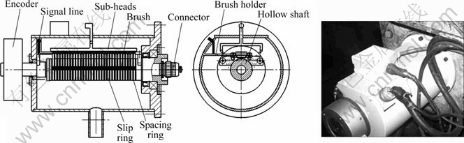
Fig. 9 Structure and sketch figure of collecting ring
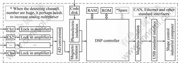
Fig. 10 DSP shape signal processing board
Within the embeded DSP shape signal processing board, the rotational speed and the rotation direction are determined by signals of the optical encoder. When the zero signal of encoder arrives, the DSP chip identifies the maximum value (positive) of each channel and the minimum (negative) at one period, and the average value of both absolute values is treated as an effective signal of one period. Then, the effective signals are real time transmitted to the signal processing software for comprehensive compensation and shape pattern recognition. Finally, the close-loop shape control is realized by the shape control system and the regulated means of mill. Figure 11 shows the shape signal processing control cabinet and its internal-embeded DSP circuit board.
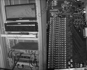
Fig. 11 DSP control cabinet and its circuit board
6 Principle of shape control
Shape control mainly includes the tilting backup roller, the positive and negative bending working roller, the positive bending middle roller, the shifting middle roller and the subsection cooling. As shown in Fig. 12, where the titling is expressed as the tilting backup roller, the WR (working roll)-bending is expressed as the bending working roller, the IR (intermediate roll)- bending is expressed as the bending middle roller and the IR-shifting is expressed as the shifting middle roller. In these rollers, the shape detecting roller and the DSP shape signal processing board are the core components of shape detecting system, which determine precisions of the shape detecting and the shape control to a great extent. So, the shape detecting system is the basis and prerequisite of achieving the close-loop shape control of cold rolling strip.
In the rolling process, radial forces are imposed on surface of the detecting roll by the strip, and passed to the sensors through the elastic blocks, then the sensors produce the original shape real-time signals (voltage signals) at the same time. After the DSP shape signal processing board receives the original shape signals via modem, AD conversion and other signal processing occur in turn. Then, the real-time digital signals are transferred to the shape signal processing software system, and the shape signals are comprehensively compensated and broken into different shape patterns. Ultimately, the close loop shape control is realized. Besides, the shape signals are real-time displayed, printed and stored in external devices.
7 Industrial applications
The shape detecting system was successfully used in Angang 1 250 mm HC 6-high reversible cold rolling mill, which verified the stability, accuracy and relevance of the system. Main steel types of cold rolling mill are carbon steel, excellent carbon steel and low alloying steel. On behalf of steel were Q195-Q235, 08Al, 16Mn, thickness range 0.2-0.55 mm of finished strip, width range 800-1 130 mm, coil diameter range 610-2 000 mm, range of wrapping angle 4°-23°, the maximum rolling speed 1 200 m/min, coiling tension range 7-140 kN. The diameter of detecting roller was 350 mm, Length 1 350 mm, effective working width 1 196 mm, effective wear thickness 6 mm, surface hardness >58 HRC. Other parameters are listed in Table 1.
Figure 13 shows the original shape peak signal of detecting roller. The channels covered by the strip have stable sensitive peak signals which are almost free from outside noises. The signals of other channels are clean and have no zero-drift phenomenon. It is the basis of the shape detecting system to correctly detect the cold strip shape in the industrial production.
Figure 14 shows real-time typical shape (edge wave, middle wave and good shape), which truly reflects actual shape status of online strip.
For example of some steel coil, product specification is 0.6 mm × 1 090 mm, material is ST12, and rolling speed is 600 m/min. Figure 15 shows lateral distributions of strip shape, where the largest shape deviation is 20 I under the open loop shape control, and 6 I under the close-loop shape control.
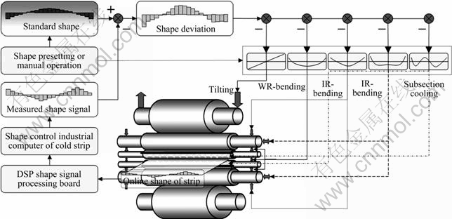
Fig. 12 Drawing of shape control
Table 1 Basic parameters of shape detecting system

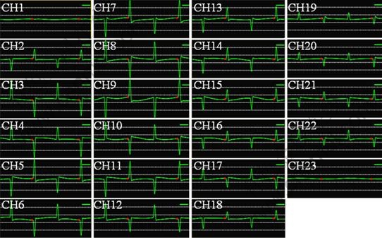
Fig. 13 Measured waves of detecting roller
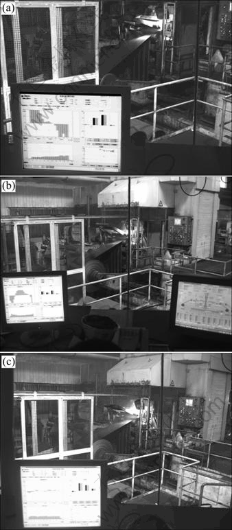
Fig. 14 Actual shape statuses of industry: (a) Edge wave; (b) Middle wave; (c) Good shape
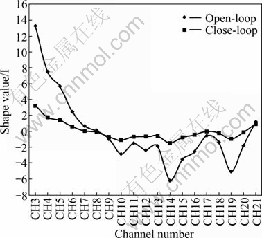
Fig. 15 Lateral distribution of measured strip shape
Figure 16 shows the longitudinal distributions of strip shape. Before the close-loop shape control applied, only pre-setting (open-loop) works, so the shape values have large fluctuations and poor stability. After the close- loop shape control applied, the shape deviations are controlled within 6 I effectively and steadily.
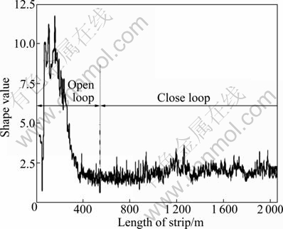
Fig. 16 Longitudinal distribution of strip shape
8 Conclusions
1) The innovative structure of internal shape detecting roller could ensure accuracy and stability of shape signal, and have many good features to meet the industrial requirements, such as high rigidity, good wear resistance, avoiding scratching the strip surface and long service period.
2) The embeded DSP shape signal processing board has high processing speed of shape signal, good anti-interference ability and reliability, powerful comprehensive compensation ability. The shape detecting precision reaches 0.2 I.
3) The close-loop shape control precision is within 6 I. It is suitable to the technological transformation and equipment upgrading of steel, aluminum, copper and other old or new cold rolling strip mills.
References
[1] XU Le-jiang. Shape control and mill type selection of cold mill strip [M]. Beijing: Metallurgical Industry Press, 2007: 100-124.
[2] WANG Guo-dong. Shape control and shape theory [M]. Beijing: Metallurgical Industry Press, 1986: 41-97.
[3] LIAN Jia-chuang, LIU Hong-min. Control of strip thickness and shape [M]. Beijing: Enginery Industry Publishing Company, 1996: 10-49.
[4] WANG Jun-sheng, BAI Jin-lan, LIU Xiang-hua. Theory and process control of cold strip rolling [M]. Beijing: Science Press, 2009: 1-25.
[5] YANG Li-hong, YAN Fei, MA Zhao-hui. Research and development of pre-coated steel for automotive industry [J]. Iron and Steel, 2009, 44(12): 1-7.
[6] ZHAI Bo, SUN Rong-sheng, SUN Jian-lin. Application of sheet shape control technology on continuous rolling mills in Angang [J]. Aisc Techniques, 2009, 355(1): 49-52.
[7] HU Guo-dong, WANG Qi, ZOU Ben-you. Differential output shape meter of mageto-elastic transformer for cold rolling strip [J]. Iron and Steel, 1994, 29(4): 56-59.
[8] XU Shi-min, YU Bing-qiang, HU Guo-dong. Shape meter of pressing magnetic type for cold rolling strip to applicating 4-roller reversible rolling mill [J]. Metallurgical Equipment, 2004, 147(5): 39-40.
[9] ZHAO Qi-lin, WANG Jun-sheng, WANG Guo-dong. Development and application of a measured flatness value processing method [J]. Journal of Materials and Metallurgy, 2009, 8(4): 294-296.
[10] WANG Jun-sheng, JIANG Zheng-yi. A flying gauge change model in tandem cold strip mill [J]. Journal of Materials Processing Technology, 2008, 201(1/2/3): 152-161.
[11] LIU Jian, WANG Yi-qun, HU Xiao-jun. Dynamic calibration of pneumatic strip shape measuring rolls and phase correction compensation method of system circumferential error [J]. Steel Rolling, 2009, 26(1): 26-29.
[12] SUN Xu-guang, WANG Yi-qun, YIN Guo-fang. Main technical performance of pneumatic strip shape measuring roll [J]. Journal of Iron and Steel Research, 2006, 18(12): 47-49.
[13] LIU Hong-min, DING Kai-rong, LI Xing-dong. Theoretical computational method of shape standard curve [J]. Chinese Journal of Mechanical Engineering, 2008, 44(8): 137-142.
[14] LIU Hong-min, HE Hai-tao, SHAN Xiu-ying. Flatness control based on dynamic effective matrix for cold strip mills [J]. Chinese Journal of Mechanical Engineering, 2009, 22(2): 287-296.
[15] SUN Ya-bo, LIU Hong-min, PENG Yan. Influence of variation of the on_line shape of cold rolled strip on shape measuring and controlling system and its compensating measures [C]// Proceedings of Second International Conference on Modeling and Simulation. Liverpool, UK, 2009: 212-219.
[16] YU Bing-qiang, LIU Hong-min, YANG Li-po. A new type of contact shape meter and its industry application [C]// International Conference on Measuring Technology and Mechatronics Automation (ICMTMA2009). Zhangjiajie, China, 2009: 1058-1061.
[17] LI Zhi-ming, PENG Yan, YU Bing-qiang. A shape measurement system for cold-rolled steel strip based on DSP [C]// 2009 WASE International Conference on Information Engineering. Dalian, China, 2009: 257-260.
[18] LIU Hong-min, YANG Li-po, YU Bing-qiang. Entire-inlayed- block- intelligence-type shape meter [P]. Chinese Patent: CN101694368A, 2010-04-07. (in Chinese)
[19] YU Bing-qiang, YANG Li-po, LIU Hong-min. Development and industry application of contact shape meter with new structure [J]. Chinese Journal of Scientific Instrument, 2010, 31(4): 904-911.
(Edited by DENG Lü-xiang)
Foundation item: Project(2009AA04Z143) supported by the National High Technology Research and Development Program of China; Project (E2011203004) supported by Natural Science Foundation of Hebei Province, China; Projects(2011BAF15B03, 2011BAF15B02) supported by the National Science Plan of China
Received date: 2011-02-15; Accepted date: 2011-04-26
Corresponding author: YANG Li-po, PhD Candidate; Tel: +86-335-8387652; E-mail: yanglp@ysu.edu.cn

