Trans. Nonferrous Met. Soc. China 27(2017) 648-655
Cap rock blast caving of cavity under open pit bench
Xi-ling LIU1,2, Ke-bing LUO1,2, Xi-bing LI1,2, Qi-yue LI1,2, Wei-hua WANG1,2, Feng-qiang GONG1,2
1. School of Resources and Safety Engineering, Central South University, Changsha 410083, China;
2. Hunan Key Laboratory of Resources Exploitation and Hazard Control for Deep Metal Mines, Changsha 410083, China
Received 1 December 2015; accepted 5 July 2016
Abstract: A laser technique based scanning system was employed to make a comprehensive scanning through borehole for unmapped cavity under open pit bench, then the three-dimensional data will be obtained, and these data were used for theoretical analysis and numerical simulation to analyze the stability of cap rock. Acoustic emission techniques were also adopted to carry out long term real time rupture monitoring in cap rock. Therefore, a complete safety evaluation system for the cap rock was established to ensure safe operation of subsequent blasting processes. The ideal way of eliminating collapse hazard of such cavity is cap rock caving through deep-hole blasting, thus, two deep-hole blasting schemes named as vertical deep-hole blasting scheme and one-time raise driving integrated with deep-hole bench blasting scheme were proposed. The vertical deep-hole blasting scheme has more explosive consumption, but the relatively simple blasting net work structure can greatly reduce workloads. However, the one-time raise driving integrated with deep-hole bench blasting scheme can obviously reduce explosive consumption, but the higher technical requirements on drilling, explosive charging and blasting network will increase workloads.
Key words: open pit mining; cavity; laser 3D detection; cap rock stability evaluation; one-time raise driving; deep-hole blasting
1 Introduction
The cavity is one of the ongoing safety problems in mines resulting in surface subsidence and roof collapses in an operating area, especially in the area where cavities are unidentified, abandoned and unmapped, and has become a serious safety hazard. We know that these cavities exist in the mined-out areas left by underground mining operations. However, some of the open pits in China have also suffered terrible tragedies resulting from underground inaccessible cavities. These cavities are unfilled and inherited from previous underground mining, and are always unmapped (hidden under the working pit), making the situation even more complicated. This is mainly caused by uncontrolled mine planning and disorderly exploitation over the past several decades. These hidden dangers can severely restrict further exploitation and threaten the safety of personnel and equipment.
It is clear that initial accurate detection and mapping of cavities under open-pit benches are vital to address safety. Currently, 3D laser scanning using a pulsed, infra-red laser, to measure the “time-of-flight” of the laser pulse to calculate distance measurements, is a means for highly accurate modeling of cavities. This laser scanning is not affected by the geology around the cavity and obtains a very clear visual 3D model of its size, shape and orientation in a very short time [1]. After the cavity has been accurately mapped, the crucial problem is to evaluate the stability of the cap rock over it based on the detailed information, and this evaluation can be established through theoretical and numerical stress status analysis, and acoustic emission monitoring in cap rock [2-6]. As the safe operation of personnel and equipment above cap rock was finally confirmed, a reasonable cavity disposal approach should be proposed.
Usually, four ways can be adopted to dispose the abandoned stope, caving, filling, support and isolation [7], because all operation works for cavities under open-pit benches should be carried out on the surface rather than from underground, the eligible ways of disposing such cavities under open pit benches are caving and filling. However, the on-site application of crushed stone backfilling through large diameter borehole shows that stope backfilling will not only greatly increase the processing costs, but affect the subsequent grade of the mining ore. Therefore, the caving method has become the initial approach to deal with such cavities. There have been many engineering researches on the caving method for underground cavity disposal. The local grooving top-caving method was adopted by LI et al [7], bench blasting by LI [8], and deep-hole blasting by YE et al [9]. Depending on the actual situation of the cavities under open-pit benches, the caving scheme should be well planned for specific engineering applications, and the data obtained from 3D laser scanning have become a necessity for detailed processing formulation of the blasting, especially for those large cavities.
The integral processing scheme which includes accurate detection and cap rock stability evaluation of a large cavity under Sandaozhuang open pit bench of the Luoyang Luanchuan Molybdenum Group Inc., China, was discussed in this work, and two types of blast caving methods were proposed and compared based on the detailed 3D laser scanned data. These proposed the stability evaluation system and blast caving methods were learnt from peer and long-term experience accumulated at the Sandaozhuang open pit. In many one-time raise driving tests, we found that the blasting results and the on-site situation encountered are very different even the designed parameters are the same and the blasting operation is located in the same area on a bench, so the need for field experience on the impact of blasting is self-evident. Thus, the parameter design in this work is not necessarily universal; however, the topics in this work can provide a good disposal pattern for such separately existed cavities, and will be a valuable reference for other similar mines.
2 Cavity detection and cap rock stability evaluation
2.1 Detailed information of cavity
A typical open pit named the Sandaozhuang Mine run by Luoyang Luanchuan Molybdenum Co., Ltd., came from an underground mine. The Sandaozhuang Mine has experienced at least 20 years of uncontrolled underground mining since the 1980s, and was totally transformed into an open-pit mine in 2003. Massive cavities were left by sublevel open-stope mining and a large number of un-cleared cavities were left by private mining. As bench blasting proceeds, the cap rock becomes thinner, and workers and equipments on benches, in which considerable labor and resources have been invested, are directly threatened by underground cavities. These cavities greatly compromise safe mine production, and addressing the safety problems of cavities is the most important task in the whole process of open-pit mining.
The large cavity under bench 1438 is chosen for analysis and handling in this study. The rock mass around the cavity is mainly skarn and wollastonite with small structural belts or magmatic rocks, and the Protodyakonov coefficient of the rock mass varies from 12 to 16. The laser scanned data are edited in Cavity- Scan processing software and a 3D modeling package, to form an oriented, geo-referenced “point cloud” (Fig. 1), which can be exported into Surpac and Computer Aided Design (CAD) software. The projected ichnography of the cavity is of particular use on-site. The data can be transformed into exploitation ichnography in CAD to outline the cavity boundary as shown in Fig. 2. We can also calculate the roof and floor elevation of any point in the projected ichnography to output cross sections by processing the scanned data. As seen in Fig. 2, the roof and floor elevations of grid intersection points are marked, and these data are required at a later design stage. By calculation, the area of the cavity is about 8683.63 m2, the volume is 157000 m3 and the thickness of cap rock is 26-68 m.
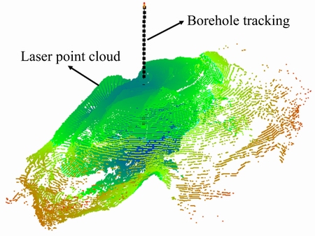
Fig. 1 Detected laser 3D point cloud of cavity under bench 1438
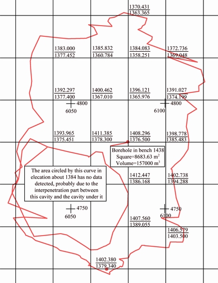
Fig. 2 Cavity ichnography with roof and floor elevation of grid intersection point (unit: m)
2.2 Cap rock stability analysis
2.2.1 Theoretical stability analysis of cap rock
3D laser detection results showed that the roofs of the detected cavities are always in horizontal and vaulted shape, so we need to choose proper methods for different shapes to calculate the stress status in cap rock over the cavity [4,10].
VAZIRI et al [11] studied an analytical model for the analysis of a rock layer over a circular opening to calculate its stability. It was assumed that the roof was axisymmetric and parabolic in shape in the vertical plane passing through the axis of symmetry. We modified the model and equations to adapt them to our case. Figure 3 illustrates the configuration of the compression arch in the cap rock [12].
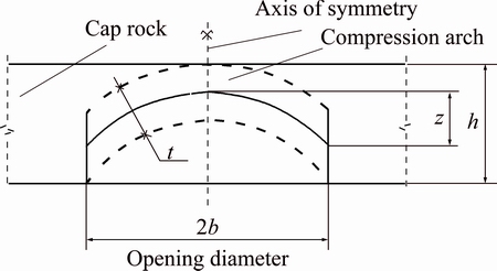
Fig. 3 Schematic of compression arch within cap rock
The maximum tangential stress (σθ)max and radial stress (σφ)max in cap rock can be calculated through the equations below:
 (1)
(1)
 (2)
(2)
where q is the stress loaded upon the compression arch; x is the horizontal coordinate with origin located in arch center; b is the half span of the arch; t is the thickness of rupture arch; z is the height of rupture arch.
The 3D laser point cloud in Fig. 1 shows that the roof of cavity is approximately in vaulted shape, so the analytical model established above can be used to calculate the stress status in cap rock, and the parameters in Eqs. (1) and (2) can be easily obtained from laser scanned data. The calculated maximum tangential stress and radial stress in cap rock of cavity under bench 1438 are (σθ)max=1.83 MPa, and (σφ)max=6.21MPa.
2.2.2 Numerical simulation based on 3D scanning data
The 3D laser scanned data can be used not only to obtain detailed information of cavity, but also to form a 3D solid model in Surpac. We then transfer this 3D solid model into FLAC3D to implement the numerical simulation [4]. Figure 4 shows the generated block model of cavity in Surpac, and Fig. 5 shows its calculation model in FLAC3D. Some results are then obtained, such as the displacement and stress distribution shown in Figs. 6 and 7, respectively. The calculated maximum tensile stress and compressive stress are 1.52 and 12.37 MPa, respectively.
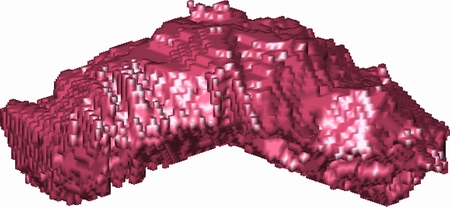
Fig. 4 Block model in Surpac of cavity under bench 1438
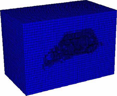
Fig. 5 Calculation model in FLAC3D
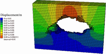
Fig. 6 Displacement distribution of single slice
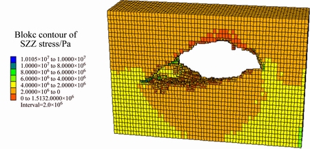
Fig. 7 Stress distribution of single slice
2.3 Acoustic emission monitoring of cap rock cracking
The cap rock over cavity will crack during its lifetime under the load of its own weight, the loads of large operating equipments above, and the loads of bench blasting. These cracking activities are the most valuable indications for cap rock stability status. As a nondestructive testing technique, acoustic emission (AE) has been widely used in geotechnical engineering for rock crack monitoring, and is ideal in our case [3,13-16].
Three parameters of AE are considered in our case: the total number of events, number of large events and energy rate. The total number of events is the cumulative number of events in unit time, and this parameter corresponds to the AE frequency. It is an important indication of damage initiation in a rock mass. The number of large events is the number of events with amplitudes greater than the set value, and this parameter corresponds to the AE extent, the proportion of large events to total events, which indicates the trend in rock mass damage. The energy rate is the cumulative value of the AE energy in unit time, which indicates the variation in damaging speed and magnitude in a rock mass.
The monitoring in cap rock of cavity under bench 1438 lasted for 20 d, and was carried out to investigate the rupturing and the effect of bench blasting on cap rock. The results are listed in Table 1.
Table 1 Cap rock acoustic emission monitoring results of cavity under bench 1438
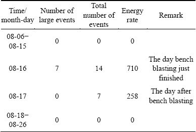
As shown in Table 1, no data were recorded before bench blasting, which meant that the cap rock was stable; data were recorded on the day bench blasting finished and the day after bench blasting, and subsequently nothing further was recorded. This indicated that the rupturing process in cap rock could have lasted for a couple of days after the end of bench blasting, and that neighboring cavities needed to be cordoned off until the cap rock became stable, but it was also possible that the blast-induced rupturing would continue and accordingly result in cap rock collapse.
3 Blast caving scheme of cap rock
The stress status calculations in cap rock through theoretical and numerical models show that the maximum stresses are much less than compressive, tensile and shear strengths of cap rock, and AE monitoring results also show that the cap rock seldom ruptures. These all indicate that the cap rock is stable, and its caving works by blasting can be done on the surface.
During the perforation design, meticulous blast-holes can be arranged throughout the cavity to sectionally view detailed data using 3D laser scanning acquisition. Taking into account the blasting crater and coefficient of volumetric expansion, a distance of less than 3 m from the boundary of the cavity without holes can be handled well. Furthermore, because of the bench blasting operations, handling hidden cavities under benches with a perforation blasting design is different from the other caving methods, with the slag being a few meters thick on the bench.
3.1 Vertical deep-hole blasting processing scheme
3.1.1 Technical measures
There are two free surfaces (bench surface and the surface toward cavity) useful for implementing blasting when using the caving method for hidden cavities under open pit benches. From the results of 3D laser scanning, the thickness of cap rock is 26-68 m, and any vertical section of the cavity is arched-high in the middle and arched-low on both sides, with a maximum vertical height of 33 m. Thus, the blasting scheme can be arranged in two steps, for those blastholes with depth greater than 30 m, the bench blasting process is used to cave those parts of cap rock which exceed 30 m, and this process can make the thickness of whole cap rock in the same 30 m. Then, the remaining parts of the cap rock are dealt with using deep-hole blasting processes which will utilize the two free surfaces and charge the blasthole in two-segment interval.
3.1.2 Blasting parameter design
Following the above technical measures, we use a 3.5 m × 5.0 m grid drilling layout which is 3.5 m between adjacent rows and 5.0 m between holes to arrange blastholes in the cap rock. The diameter of the blastholes is 140 mm, the depth is 28-68 m, and they are arranged as shown in Fig. 8. A sectional view of the distribution of blastholes is shown in Fig. 9. There are 468 blastholes and 16625 m long in total.
Based on the previous experience of bench blasting and handling of a small cavity, the explosive consumption of 0.67 kg/m3 is used, and the explosive charge is 178400 kg. The charging structure depends on the depth of the blasthole, which involves three-segment interval charging for blastholes with depth greater than 30 m and two-segment interval charging for blastholes with depth less than 30 m. The top blockage is 4.0 m, the bottom blockage is 3.0 m, and the middle blockage is 3.0 m. The charging structure diagram is shown in Fig. 10.
Fig. 8 Blasthole layout of vertical deep-hole blasting processing scheme (unit: m)
Fig. 9 Sectional view of some blastholes in Fig. 8
3.2 One-time raise driving integrated with deep-hole bench blasting
3.2.1 Technical measures
Because the area and volume of cavity under bench 1438 are huge, and the thickest parts of cap rock are close to 68 m, so the blasting confinement is more critical and more explosives will be consumed if the deep-hole blasting process scheme is implemented, therefore the size of blasted and flying rocks will be difficult to control. Considering our previous successful experiments in this open pit using one-time deep-hole blasting raise driving technology for the formation of stone filling raises in cap rock over cavities, the choice of a specific method and the parameters of the blasting were given by LI et al [17] who designed to form a raise by one-time deep hole blasting with depth up to 45 m. A summary of test results found that the ideal mode of one-time raise driving by blasting was vertical crater retreat integrated with pre-split blasting, which initially used small diameter pre-split blastholes around the raise periphery, followed by segmented charged large diameter blastholes in the raise. For large cavities such as the one under bench 1438, using one-time raise driving technology on the minimum thickness parts of cap rock to form a large section of the raise, which can provide a free surface for blasting to handle the remaining cap rock with bench blasting process. This blasting scheme is not only able to cave the cap rock successfully, but also can effectively control blasting fragmentation and flying rocks. However, it was found from the previous one-time raise driving tests that, because the value of slag on bench surface and the diameter of raise heads were much larger than the designed ones even though the height and the charge amount of upper two segments were deliberately reduced. This enlargement of raise head will influence the subsequent drilling of the first circle deep holes around the raise. Thus, a circle of deep holes with diameter of 140 mm (we call them raise modification blastholes) charged in two segments was designed to blast the raise in same diameter.
Fig. 10 Two types of charging structures of vertical deep-hole blasting processing scheme
3.2.2 Blasting parameter design of one-time raise driving technology
The position of the raise on bench 1438 is selected at the place with minimum thickness of cap rock. The designed final shape of the raise is 30 m in depth and 17.4 m in diameter. The rational matching of pre-splitting blasting holes and large diameter holes is the key to one-time raise driving technology, which has more ideal blasting parameters derived from a number of spot experiments.
Pre-splitting blastholes: The diameter of the holes is 140 mm and the distance between them is 1.3 m. 25 holes are distributed evenly on the circumference of a circle with a diameter of 10.4 m, which introduce uncoupled charge blasting with a linear charging density of 1.61 kg/m, and the bottom and top blockages are 0.8 and 2.0 m, respectively.
Large diameter blastholes: The diameter of the holes is 250 mm. One hole is located at the center of the raise, 6 holes and 12 holes are distributed evenly on the circumferences of two circles with diameters of 4 and 7.6 m, respectively. A layered coupling charge system with charging height of 1.0 m and blockage height of 2.0 m is introduced for large diameter blastholes.
Raise modification blastholes: 13 holes are distributed evenly on the circumference of a circle with a diameter of 17.4 m as referenced in the bench blasting parameters of Sandaozhuang open pit. The diameter of the holes is 140 mm, the bottom blockage is 3.0 m, the middle blockage is 3.0 m, the top blockage is 4.0 m and the other two parts are continuously charged.
The arrangement of the blastholes is shown in Fig. 11. The blasting sequence starts with the pre-splitting blastholes followed by the large diameter blastholes, and then the raise modification blastholes. The charging structure and millisecond delay of each charge section are shown in Fig. 12.
Fig. 11 Blasthole layout of one-time raise driving
Fig. 12 Charging structure and millisecond delay of blastholes on A-A section in Fig. 11
3.2.3 Parameter design of deep-hole bench blasting
Free surfaces for the subsequent rock blasting through the large section raise are generated by one-time raise driving technology. The arrangement of blastholes in circles with diameter of 140 mm around generated raise is shown in Fig. 13. The distance between circles is 3.5 m and that between blastholes is 5.0 m, and the explosive consumption is 0.54 kg/m3 as referenced in the bench blasting parameters. The charging structure diagram of blastholes is shown in Fig. 14.
Fig. 13 Blasthole layout of one-time raise driving integrated with deep-hole bench blasting processing scheme (unit: m)
Fig. 14 Two types of charging structures of one-time raise driving integrated with deep-hole bench blasting processing scheme
3.3 Comparison of two caving schemes
Cap rock blasting caving treatment demands to be economical, effective and safe, and the process operation should be as simple as possible. Thus, the consumption of explosives, drilling quantities, blasting networks and blasting fragmentation should be taken into account, and the blasting safety such as the greatest throwing distances of flying rock should also be evaluated. Table 2 illustrates the parameters of blasting methods. The vertical deep-hole blasting processing scheme needs more explosive charge per hole and overall explosive consumption, and blasting fragmentation is not easy to control, because of the confinement of the strong blasting and less free surface. However, a significant advantage of this scheme is that the relatively simple blasting network structure can greatly reduce the workload and working time, which will undoubtedly improve the operation safety on the cap rock that could collapse during the processing period even various measures were adopted before evaluating its safety such as stability analysis and stability monitoring. The large section raise generated by one-time raise driving provides free surfaces, similar to bench blasting, for the subsequent blasting. This can obviously reduce the explosive charge per hole and consumption of explosive, and also easily control blasting fragmentation. However, the greater requirements of the technology such as drilling precision, placing charged explosive and the blasting network, will make the work more difficult and increase working time. If the cap rock stability over cavity can be well ensured, the processing scheme of one-time raise driving integrated with deep-hole blasting is an ideal one for such cap rock caving. Figure 15 shows the collapsed cap rock of cavity under bench 1438 after blasting, and the unknown laneways occurring inside cap rock can somehow influence blasting results, thus the detailed investigation of cap rock is extremely important.
Table 2 Parameters for dealing with two types of cavity blasting
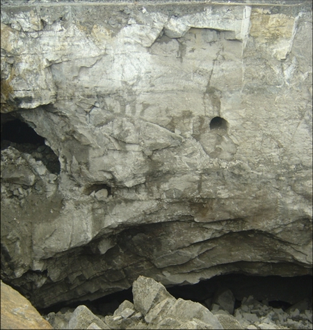
Fig. 15 Collapsed cap rock of cavity under bench 1438 after blasting
4 Conclusions
1) 3D laser scanner can be deployed through borehole to the cavity to obtain 3D coordinates of any point of the roof and form a very clear visual 3D model. The detailed probe data of a cavity can be used to evaluate the stability of the cap rock, delineate the boundary of the cavity, and provide an accurate volume of the cap rock and the drilling depths for each hole in deep-hole blasting. Thus, the detailed cavity detection is the precondition for cap rock caving.
2) One-time raise driving integrated with deep-hole blasting is undoubtedly an ideal processing scheme for the two caving methods proposed in this work; however, it should be considered that this processing scheme especially the part of one-time raise driving will increase working time and the difficulty of the workload which will affect the normal operation of other tasks.
3) Despite the safety assessment of the stability analysis and monitoring of cap rock over cavities, any impact of a large section of the raise on the stability of the cap rock should be noted. Therefore, the selection of a caving method of cavity is dependent on the detailed information of cavity and the mine production situation, but it is particularly important to consider the safety of the processing scheme.
References
[1] LIU Xi-ling, LI Xi-bing, LI Fa-ben, ZHAO Guo-yan, QIN Yu-hui. 3D cavity detection technique and its application based on cavity auto scanning laser system [J]. Journal of Central South University of Technology, 2008, 15(2): 285-288.
[2] LIU Xi-ling, LI Xi-bing, LIU Ke-wei, WANG Wei-hua, ZHOU Zi-long. Laser 3D detection and stability analysis of underground cavity [J]. Journal of China University of Mining & Technology, 2009, 38(4): 549-553. (in Chinese)
[3] LIU Xi-ling, LI Xi-bing, GONG Feng-qiang, LI Di-yuan. Safety isolation layer thickness and acoustic emission monitoring of cavity under open pit benches [J]. Chinese Journal of Rock Mechanics and Engineering, 2012, 31(S1): s3357-s3362. (in Chinese)
[4] LIU Xi-ling, LI Xi-bing, GONG Feng-qiang, LIU Ke-wei. Safety problem of cavity under open pit bench [J]. Archives of Mining Sciences, 2015, 60(2): 613-628.
[5] TAO Ming, LI Xi-bing, WU Cheng-qing. 3D numerical model for dynamic loading-induced multiple fracture zones around underground cavity faces [J]. Computers and Geotechnics, 2013, 54(10): 33-45.
[6] TAROKH A, BLANKSMA D J, FAKHIMI A, LABUZ J F. Fracture initiation in cavity expansion of rock [J]. International Journal of Rock Mechanics and Mining Sciences, 2016, 85: 84-91.
[7] LI Jun-ping, FENG Chang-gen, ZHOU Chuang-bing, ZHENG Zhao-qiang. Study of basic parameters on local grooving top-caving with controlled explosion [J]. Chinese Journal of Rock Mechanics and Engineering, 2004, 23(4): 650-656. (in Chinese)
[8] LI Ke. Treatment of mined-out spaces in Yinshan openpit mine by blasting method [J]. Mining & Metallurgy, 2002, 11(4): 12-16. (in Chinese)
[9] YE Tu-qiang, ZENG Xi-long, LIN Qin-he, CAI Jin-bin. Practice of solving large mined-out area by open deep hole blasting [J]. China Mining Magazine, 2008, 17(8): 97-101. (in Chinese)
[10] SWIFT G M, REDDISH D J. Stability problems associated with an abandoned ironstone mine [J]. Bulletin of Engineering Geology and the Environment, 2002, 61(3): 227-239.
[11] VAZIRI H H, JALALI J S, ISLAM R. An analytical model for stability analysis of rock layers over a circular opening [J]. International Journal of Solids and Structures, 2001, 38(21): 3735-3757.
[12] LIU Xi-ling. Research for stability analysis and safety forewarning of cavity based on laser 3D detection [D]. Changsha: Central South University, 2008. (in Chinese)
[13] GROSSE C U, OHTSU M. Acoustic emission testing-basics for research and applications in civil engineering [M]. Berlin: Springer, 2008: 11-18.
[14] DONG Long-jun, LI Xi-bing, ZHOU Zi-long, CHEN Guang-hui, MA Ju. Three-dimensional analytical solution of acoustic emission source location for cuboid monitoring network without pre-measured wave velocity [J]. Transactions of Nonferrous Metals Society of China, 2015, 25(1): 293-302.
[15] FALLS S D, YOUNG R P. Acoustic emission and ultrasonic-velocity methods used to characterise the excavation disturbance associated with deep tunnels in hard rock [J]. Tectonophysics, 1998, 289(1-3): 1-15.
[16] SHIOTANI T. Evaluation of long-term stability for rock slope by means of acoustic emission technique [J]. NDT&E International, 2006, 39(3): 217-228.
[17] LI Qi-yue, LI Xi-bing, FAN Zuo-peng, ZHANG Rui-hua. One time deep hole raise blasting technology and case study [J]. Chinese Journal of Rock Mechanics and Engineering, 2013, 32(4): 664-670. (in Chinese).
露天台阶面下伏空区顶板的爆破崩落处理
刘希灵1,2,罗克冰1,2,李夕兵1,2,李启月1,2,王卫华1,2,宫凤强1,2
1. 中南大学 资源与安全工程学院,长沙 410083; 2. 深部金属矿产资助开发与灾害控制湖南省重点实验室,长沙 410083
摘 要:基于激光三维扫描技术构建空区三维实体模型,运用理论分析和数值模拟的方法对空区上覆岩层的稳定性进行分析;采用声发射技术对空区上覆岩层进行跟踪监测,形成空区上覆岩层安全性的评价体系。同时,提出了运用垂直深孔爆破消空处理和一次成井及深孔爆破消空一体化处理两种空区处理方案,将两种方案进行对比分析后发现,垂直深孔爆破消空处理方案炸药单耗和总装药量较大,但其爆破网络结构简单,现场作业量小。而一次成井及深孔爆破消空一体化处理方案炸药单耗和总装药量小,但对钻孔精度、装药及爆破网络连接等都有较高的要求,现场作业量大。
关键词:露天开采;采空区;激光三维探测;空区稳定性评价;一次成井;深孔爆破
(Edited by Wei-ping CHEN)
Foundation item: Projects (51204206, 41272304, 41372278) supported by the National Natural Science Foundation of China
Corresponding author: Xi-bing LI; Tel: +86-731-88879612; E-mail: xbli@csu.edu.cn
DOI: 10.1016/S1003-6326(17)60072-4

