J. Cent. South Univ. Technol. (2011) 18: 310-313
DOI: 10.1007/s11771-011-0696-4
Effect of Al and Si additions on microstructure and mechanical properties of TiN coatings
WANG She-quan(����Ȩ)1, 2, CHEN Kang-hua(�¿���)1, CHEN Li(����)2,
ZHU Chang-jun(ף����)1, LI Ping(����)2, DU Yong(����)1
1. State Key Laboratory of Powder Metallurgy, Central South University, Changsha 410083, China;
2. Zhuzhou Cemented Carbide Cutting Tools Co., Ltd, Zhuzhou 412007, China
? Central South University Press and Springer-Verlag Berlin Heidelberg 2011
Abstract: Ti-X-N (X=Al, Si or Al+Si) coatings were grown onto cemented carbide substrates by cathodic arc evaporation. The hardness of the coatings was obtained by nanoindentation and the microstructure was investigated by XRD, XPS and SEM. Solid solution hardening results in a hardness increase from 24 GPa for TiN to 31.2 GPa for TiAlN. The higher hardness values of 36.7 GPa for TiSiN and 42.4 GPa for TiAlSiN are obtained by the incorporation of Si into TiN (TiAlN) coatings due to the formation of special three-dimensional net structure consisting of nanocrystalline (nc) TiN (TiAlN) encapsulated in an amorphous (a) Si3N4 matrix phase. Furthermore, the nc-TiAlN/a-Si3N4 coating shows the best machining performance.
Key words: TiN coating; alloying element; hardness; cutting test
1 Introduction
TiN coatings, which have served for thirty years in industrial applications, have still been studied extensively today due to their relatively high hardness and wear resistance [1-2]. However, at temperatures above 500 ��C they start to oxidize into TiO2, resulting in the crack formation and the delamination of the brittle oxide layer, which will deteriorate the mechanical and tribological properties [1-2]. Recently, a lot of efforts were done by alloying TiN based coatings with several elements acting in different ways [3-5]. Among them, the coatings by the incorporation of Al and Si into TiN attract more attention for cutting applications [6-8]. Ti-Al-N coatings become the most widely used coatings in cutting tool due to their better oxidation resistance, higher hardness and improved thermal stability as compared with TiN. A further increase in hardness can be acquired by Ti-Si-N coatings via the formation of nanocomposite structure where amorphous (a) Si3N4 boundary layers encapsulate nanocrystalline (nc) TiN grains [9-11]. Furthermore, the improvement in their properties can be obtained by incorporation of Si into TiAlN coatings [10-11]. The purpose of this work is to investigate the effect of incorporating Al and Si into TiN coatings on the mechanical properties and the microstructural evolution of the coatings.
2 Experimental
2.1 Coating deposition
Ti-N, Ti-Al-N, Ti-Si-N and Ti-Al-Si-N coatings were deposited onto powder metallurgically prepared CNMG120408 style cemented carbide (WC-6%Co, mass fraction) substrates by a commercial cathodic arc evaporation system (Balzers Oerlikon Rapid Cooling System, RCS, Liechtenstein) from Ti, Ti0.50Al0.50, Ti0.94Si0.06 and Ti0.47Al0.47Si0.06 (molar fraction, %) targets. Prior to the deposition with a two fold substrate-rotation fixture in N2 (99.99% in purity) atmosphere at about 2 Pa, -100 V DC substrate bias and 550 ��C, the substrates were cleaned by an argon-ion-etching process.
2.2 Characterization
The elemental compositions of the coatings were determined using electron probe microanalysis (EMPA) (JXA-8800R, JEOL, Japan). Structural investigations were conducted by X-ray diffractometry (XRD) with Cu K�� radiation using a Bruker D8 in Bragg/Brentano mode. The grain size was determined by the single method for analysis of XRD line broadening using a Pseudo-Voigt profile function [12]. The hardness of the coatings was obtained by nanoindentation with a Fischerscope H100VP based on the Oliver and Pharr method [13]. According to the experimental results of the large-load (30 mN) penetration test, a smaller penetration load of 8 mN was chosen to measure the mechanical properties of the coatings. The bonding structure of the Ti-Si-N and Ti-Al-Si-N coatings was characterized by XPS using a RBD upgraded PHI-5000C ESCA system (Perkin Elmer) with Mg K�� radiation (hn=1 253.6 eV) or Al K�� radiation (hn=1 486.6 eV). In general, the X-ray anode was run at 250 W and the high voltage was kept at 14.0 kV with a detection angle of 54��. The pass energy was fixed at 23.5, 46.95 or 93.90 eV to ensure sufficient resolution and sensitivity. The base pressure of the analyzer chamber was about 5?10-8 Pa. The sample was directly pressed to a self-supported disk (10 mm?10 mm), mounted on a sample holder, and then transferred into the analyzer chamber. The whole spectra (0-1 100 (1 200) eV) and the narrow spectra of the elements with much high resolution were both recorded using RBD 147 interface (RBD Enterprises, USA) through the AugerScan 3.21 software. Binding energies were calibrated using the containment carbon (C 1s 284.6 eV). The data analysis was carried out using the RBD AugerScan 3.21 software provided by RBD Enterprises or XPSPeak4.1 provided by Raymund W. M. Kwok (Chinese University of Hongkong, China).
2.3 Cutting tests
Continuous dry turning of stainless steel (1Cr18Ni9Ti) with CNMG120408-EM style inserts (WC-6% Co) was conducted with a cutting speed (vc) of 200 m/min, a depth of cut (ap) of 1.0 mm and a feed rate (f) of 0.2 mm/r.
3 Results and discussion
EPMA measurements show that the nitride coatings have elemental compositions of Ti0.52Al0.48N, Ti0.94Si0.06N and Ti0.48Al0.46Si0.06N. Hence, the molar fractions in the coating correspond to those of the targets. Fig.1 shows the XRD patterns of the as-deposited coatings. Analysis of the XRD results reveals that all the coatings as-deposited exhibit a single-phase NaCl structure. The diffraction peaks of TiAlN coating, which show a preferred orientation on crystal plane of (200), shift to higher angle owing to the decrease of the lattice constant arising from the replacement of Ti atoms in the TiN lattice by Al. In the case of the TiSiN and TiAlSiN coatings, no signals from crystal SixNy or from titanium silicide could be observed. This result implies that Si is present in an amorphous phase of either compound or simple substance. With the addition of Al and Si, decreased grain size is observed, which is shown from the reduced intensity of XRD peaks as well as peak broadening. The determination of the average crystallite size using broadening of the XRD peaks indicates an average crystallite size of approximately 24.7 nm for TiN coating, about 18.6 nm for TiAlN coating, about 10 nm for TiSiN coating and about 3.6 nm for TiAlSiN coating, respectively. In general, the crystallite size using XRD is smaller than the actual crystallite size due to the solution strain and residual stress.
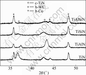
Fig.1 XRD patterns of Ti-X-N coatings
The chemical bonding state of N and Si was characterized by XPS. Fig.2 shows the XPS core-level spectra of N 1s and Si 2p electrons from the as-deposited TiSiN and TiAlSiN coatings. The N 1s spectrum of coatings reveals the presence of two peaks (see Fig.2(a)). The high-intensity peaks at approximately 396.5 eV can be assigned to the binding energy of N 1s electron in TiN or AlN, as the binding energies of TiN and AlN have been reported to be very similar, 396.7 and 396.8 eV, respectively [9]. The high-intensity peak position shifts from 396.5 to 397.1 eV with the addition of Al. The low intensity peaks of N 1s centered at almost 399 eV can be assigned to the binding energy of N 1s electrons of Si3N4. Analysis of the binding energy from Si 2p peak (see Fig.2(b)) shows a very little difference from the reported value of Si3N4 at 101.8 eV for these coatings [9]. Thus, Si in these coatings prefers to the formation of Si��N bonds rather than the formation of silicides. To corroborate the above presented XRD results, it can be concluded that the deposited coatings are composed of nc-TixAl1-xN and a-Si3N4.
As shown in Figs.3(a) and (b), the cross-sectional SEM images of TiN and TiAlN coatings exhibit a pronounced columnar structure. Decreased grain size of TiAlN coating, which is in good agreement with the XRD results, can be observed. With the Si addition, the columnar structure vanishes, and a dense smooth structure is found for the TiSiN and TiAlSiN coatings, as demonstrated in Figs.3(c) and (d). It is further verified that the TiSiN coating is of nanocomposite (nc-Ti1-xAlxN/ a-Si3N4) structure, whereas amorphous Si3N4 boundary layers encapsulate nanocrystalline Ti1-xAlxN grains. The formation of nc-Ti1-xAlxN/a-Si3N4 coatings is a characteristic of self-organization process during deposition, which has been widely investigated [8-11]. TiSiN system undergoes a strong thermodynamically driven phase segregation into TiN and Si3N4 due to the immiscibility of both phases [14]. However, it is a debatable question whether the nanocomposite structure is formed by a spinodal decomposition, as proposed by ZHANG and VEPREK [11].
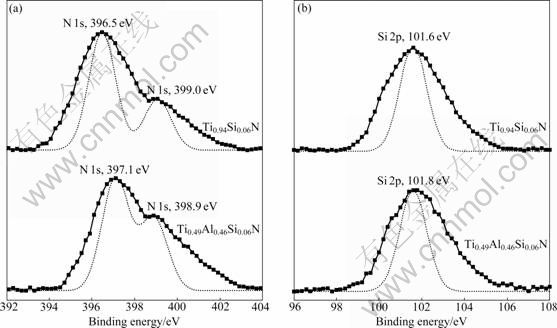
Fig.2 XPS spectra of N 1s (a) and Si 2p (b) peaks for TiSiN and TiAlSiN coatings
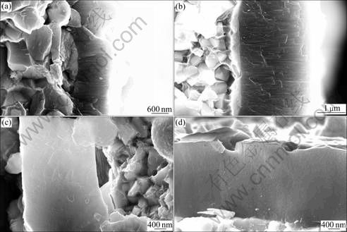
Fig.3 Cross-sectional SEM images of Ti-X-N coatings: (a) TiN; (b) TiAlN; (c) TiSiN; (d) TiAlSiN
With the incorporation of Al, a significant increase in hardness is obtained from about 23.4 GPa for TiN to about 31.2 GPa for TiAlN as a result of solid solution hardening. A further increase in hardness value of about 35.7 GPa is acquired for the TiSiN coating. The combined hardening effects of grain size refinement and the strong interphase boundary between TiAlN crystallite and amorphous Si3N4 tissue phase with high cohesive energy should be responsible for the hardness enhancement. The ratio of Si3N4 tissue phase to the specific interface of the TiN nanocrystalline phase as well as Si3N4 phase content, which depends on the TiN crystallite size and shape, also plays a decisive role in hardness value of nanocomposite nc-TiN/a-Si3N4 coatings, as reported by VEPREK et al [7]. The crystallites of regular shape with a size of about 3-4 nm for the nc-MenN/a-Si3N4 systems, where the thickness of the a-Si3N4 layer is about 0.3-0.5 nm, i.e., about one monolayer of a-Si3N4, give rise to the maximum hardness [7]. The maximum hardness value of about 42.4 GPa for TiAlSiN coatings is acquired with decreasing TiAlN grain size to 3.6 nm. In addition, the solution hardening incorporation of more Al can also be attributed to the increased hardness.
Fig.4 shows the comparison of the lifetime of as-deposited coating inserts during continuous turning of stainless steel 1Cr18Ni9Ti. A significant increase in cutting lifetime of coated inserts with the addition of Al is obtained. And TiSiN coated inserts perform much better than TiAlN coated inserts with an increase of lifetime by 150%. However, the best cutting performance is obtained by the TiAlSiN coated inserts. For continuous turning, the tool life is mainly controlled by the thermal stability and hardness of the coating. For cutting with higher speed, more heat generated within the chip-tool contact zone, in comparison with low-speed cutting, causes a temperature increase on the cutting edge of the inserts, probably up to 1 000 ��C. The excellent high- temperature hardness and thermal stability of TiAlSiN coating ensure its performance during high-speed machining. Additionally, this result may also be attributed to higher oxidation resistance and lower thermal conductivity of TiAlSiN coating.
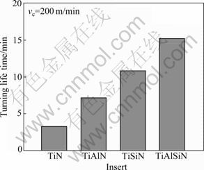
Fig.4 Lifetime of Ti-X-N coated inserts during continuous turning of stainless steel
4 Conclusions
1) Al- and Si-containing coatings have the same single-phase NaCl structure with TiN coating.
2) The addition of Al and Si significantly decreases the grain size from 24.7 nm for TiN to 18.6 nm for TiAlN to 10 nm for TiSiN coating and to 3.6 nm for TiAlSiN coating.
3) Solid solution hardening results in a hardness increase from 24 GPa for TiN to 31.2 GPa for TiAlN. The higher hardness value of 36.7 GPa for TiSiN and 42.4 GPa for TiAlSiN is obtained by the incorporation of Si into TiN and TiAlN coatings due to the formation of special three-dimensional net structure consisting of nc-TixAl1-xN encapsulated in an amorphous a-Si3N4 matrix phase.
4) Compared with TiN coated inserts, the cutting behavior is improved with the incorporation of Al and Si. The best cutting performance is obtained for the TiAlSiN coated inserts.
References
[1] SUNDGREN J E. Structure and properties of TiN coatings [J]. Thin Solid Films, 1985, 128: 21-44.
[2] MILOSEV I, STREHBLOW H H, NAVINSEK B. XPS in the study of high-temperature oxidation of CrN and TiN hard coatings [J]. Surface and Coatings Technology, 1995, 74/75: 897-902.
[3] POLAKOVA H, MUSIL J, VICEK J, ALLAART J, MITTERER C. Structure-hardness relations in sputtered Ti-Al-V-N films [J]. Thin Solid Films, 2003, 444: 189-198.
[4] CHEN L, DU Y, WANG S Q, LI J. A comparative research on physical and mechanical properties of (Ti, Al)N and (Cr, Al)N PVD coatings with high Al content [J]. International Journal of Refractory Metals and Hard Materials, 2007, 25: 400-404.
[5] VEPREK S, ARGON A S. Towards the understanding of mechanical properties of super- and ultrahard nanocomposites [J]. Journal of Vacuum Science & Technology B, 2002, 20: 650-664.
[6] VEPREK S, REIPRICH S, LI S Z. Superhard nanocrystalline composite materials: The TiN/Si3N4 system [J]. Applied Physics Letters, 1995, 66: 2640-2642.
[7] VEPREK S, VEPREK-HEIJMAN G J M G J, KARVANKOVA P, PROCHAZKA J. Different approaches to superhard coatings and nanocomposites [J]. Thin Solid Films, 2005, 476: 1-29.
[8] VEPREK S, PEIPRICH S. A concept for the design of novel superhard coatings [J]. Thin Solid Films, 1995, 268: 64-71.
[9] M?NNLING H D, PATIL D S, MOTO K, JILEK M, VPREK S. Thermal stability of superhard nanocomposite coatings consisting of immiscible nitrides [J]. Surface and Coatings Technology, 2001, 146/147: 263-267.
[10] VEPREK S. The search for novel, superhard materials [J]. Journal of Vacuum Science & Technology A, 1999, 17: 2401-2420.
[11] ZHANG R F, VEPREK S. Phase stabilities of self-organized nc-TiN/a-Si3N4 nanocomposites and of Ti1-xSixNy solid solutions studied by ab initio calculation and thermodynamic modeling [J]. Thin Solid Films, 2008, 516: 2264-2275.
[12] MAYRHOFER P H, TISCHLER G, MITTER C. Microstructure and mechanical/thermal properties of Cr-N coatings deposited by reactive unbalanced magnetron sputtering [J]. Surface and Coatings Technology, 2001, 142/143/144: 78-84.
[13] OLIVER W C, PHARR G M. An improved technique for determining hardness and elastic modulus using load and displacement sensing indentation experiments [J]. J Mater Res, 1992, 7: 1564-1583.
[14] ZHANG R F, VEPREK S. On the spinodal nature of the phase segregation and formation of stable nanostructure in the Ti-Si-N system [J]. Materials Science and Engineering: A, 2006, 424: 128-137.
(Edited by YANG Bing)
Foundation item: Project(50721003) supported by Creative Research Group of National Natural Science Foundation of China; Project(2009ZX04012-021) supported by the National Major Special Science and Technology Program of China
Received date: 2010-04-01; Accepted date: 2010-05-26
Corresponding author: CHEN Kang-hua, Professor, PhD; Tel: +86-731-88830714; E-mail: khchen@mail.csu.edu.cn

