添加剂对从无氰电解质中电沉积铜的协同效应及其结构和形貌特征
来源期刊:中国有色金属学报(英文版)2017年第7期
论文作者:R. SEKAR
文章页码:1665 - 1676
关键词:协同效应;葡萄糖酸盐;添加剂;原子力显微镜;电沉积;铜
Key words:synergistic effect; gluconate; additive; atomic force microscopy; electrodeposition; copper
摘 要:由于铜在低碳钢上的伽伐尼置换反应,酸性铜板在低碳钢基体上的电沉积比较困难。使用一种适宜的络合剂可解决这一问题,因为络合剂能通过形成配位化合物降低铜的电位。本文作者研究在碱性介质中以葡萄糖酸钠为络合剂从无氰电解质中电沉积铜。考察1,2,3-苯并三唑、十二烷基硫酸钠、聚乙二醇-800和糖精等添加剂对铜电沉积的影响。结果表明,这类添加剂不仅能降低电沉积铜的晶粒尺寸和晶界、改善其表面形貌,而且能提高电解质的均镀能力及电沉积铜的硬度。采用X射线衍射技术(XRD)对沉积铜进行表征。XRD结果表明,电沉积铜为多晶和面心立方结构。利用XRD结合原子力显微镜(AFM)计算电沉积铜的晶粒尺寸。在所研究的添加剂中苯并三唑和十二烷基酸钠混合添加剂的效果最好。用扫描电镜观察到的均匀无孔表面及AFM结果显示,上述添加剂能使电沉积铜的晶粒细化。
Abstract: Electrodeposition of acid copper plating on mild steel substrate is tedious due to the galvanic displacement reaction of copper on mild steel. This can be avoided by using a proper complexing agent, because the complexing agent tuned the potential of noble direction to less noble direction by complex formation. In this paper, environment friendly electrodeposition of copper from non-cyanide electrolyte using sodium gluconate as complexing agent was investigated in alkaline medium. The effects of additives such as 1, 2, 3-benzotriazole, sodium lauryl sulphate, PEG 8000 and saccharin were studied. These additives are found to reduce the grain size, grain boundaries and improve surface morphology of the copper deposits. Also they improve the throwing power of the depositing electrolytes and hardness of deposits. The electrodeposited copper coatings were characterized by X-ray diffraction technique. XRD results indicate that the electrodeposited copper shows polycrystalline and face centered cubic structure. The crystal size was calculated by XRD and AFM analysis. Among these additives studied, the mixture of benzotriazole and sodium lauryl sulphate acts as the best additive. A uniform pore-free surface observed under SEM and AFM results reveal the grain refining brought about by the additives.
Trans. Nonferrous Met. Soc. China 27(2017) 1665-1676
R. SEKAR
Electroplating and Metal Finishing Technology Division, Central Electro Chemical Research Institute, Karaikudi 630006, Tamil Nadu, India
Received 18 May 2016; accepted 24 December 2016
Abstract: Electrodeposition of acid copper plating on mild steel substrate is tedious due to the galvanic displacement reaction of copper on mild steel. This can be avoided by using a proper complexing agent, because the complexing agent tuned the potential of noble direction to less noble direction by complex formation. In this paper, environment friendly electrodeposition of copper from non-cyanide electrolyte using sodium gluconate as complexing agent was investigated in alkaline medium. The effects of additives such as 1, 2, 3-benzotriazole, sodium lauryl sulphate, PEG 8000 and saccharin were studied. These additives are found to reduce the grain size, grain boundaries and improve surface morphology of the copper deposits. Also they improve the throwing power of the depositing electrolytes and hardness of deposits. The electrodeposited copper coatings were characterized by X-ray diffraction technique. XRD results indicate that the electrodeposited copper shows polycrystalline and face centered cubic structure. The crystal size was calculated by XRD and AFM analysis. Among these additives studied, the mixture of benzotriazole and sodium lauryl sulphate acts as the best additive. A uniform pore-free surface observed under SEM and AFM results reveal the grain refining brought about by the additives.
Key words: synergistic effect; gluconate; additive; atomic force microscopy; electrodeposition; copper
1 Introduction
Recently, copper has been replacing aluminium as a metal for interconnects in the electronic industry because copper has unique properties like lower resistivity and superior resistance against to electromigration compared with aluminum alloys. Copper can be deposited by several methods, such as physical vapour deposition, chemical vapour deposition, electroless and electrodeposition. Among these methods electrodeposition offers several advantages: it has the highest current efficiency and deposition rate, it is the least expensive, highly productive, low toxic and readily adoptable [1-3]. Electrodeposited copper films have been extensively studied with respect to their morphological characteristics, corrosion resistance, electrical properties and thermal resistance [4,5]. A detailed study of copper deposition on stainless steel from a copper sulphate bath had been undertaken with the application of square wave pulse current and direct current [6]. MANTRY et al [7] investigated the deposition of plasma sprayed copper coatings on metal substrates for various engineering and structural applications. ZHU et al [8] developed a copper hydroxide and citrate bath for electrodepositing copper coating as the substrate of electroplating nickel on AZ31 magnesium alloy and observed surface and cross-section morphologies of copper coating using SEM, to examine adhesion strength of copper coating using scratched grid test and to assess corrosion performance using immersion test. Electroplating parameters like bah composition, temperature, current density, mode of current, a variety of films with various characteristics can be achieved, thus allowing to tailor the mechanical characteristics of the coatings for specific applications. SEKAR et al [9] investigated the electrodeposition of copper from glycerol complex in an alkaline medium, and the influence of additives in glycerol complex electrolyte. PAK et al [10] studied the copper matrix composite fabricated by extrusion process and the mechanical properties using indentation technique. The carbon nanotube content increases with increasing yield strength, tensile strength and hardness of the Cu-CNTs composites can be obviously improved. The mechanism for the mechanical response to the loading rate and the aspect ratio of copper-based bulk metallic glasses was discussed by CAI et al [11]. SEKAR et al [12] investigated an electroless copper depositing bath using double complexing agent to improve the self life of the bath and prevent the formation of precipitation of copper complexes. Paraformaldehyde and 2-mercaptobenzothiozole were used as reducing agent and stabilizer, respectively. Gelatin and animal glue were used as grain refiners. The deposits were characterized using various techniques such as XRD, SEM and AFM, and corrosion behavior of the coatings was examined using potentiodynamic polarization and electrochemical impedance spectroscopy [12]. JAIN et al [13] made an attempt to the synthesis of size-controlled copper nanoparticles through a simple one phase aqueous route using ascorbic acid as reducing agent and capping agent and catalytic actives of these particles with different sizes have been tested on the oxidation of serine. In modern electroplating practice, it is well known that the addition of even small amounts of certain substances in the plating baths leads to significant changes in the properties and aspect of the deposit. Recent reviews have tried to summarize their different effects such as levelers, brighteners and wetting agents [14-16]. The most common leveling and brightening agents used in copper electrodeposition are thiourea [17,18], gelatin [19], benzotriazole [20,21], and polyethylene glycol [22,23] for modifying the surface morphology of the coatings. Electrodeposition of copper and its alloys from alkaline cyanide electrolytes has been extensively used for industrial level production of coatings of good quality deposits. Cyanide plating is used in all the metal finishing industries for many applications, even though not as widely today as in the 1970s because of environmental issues [24]. Worker safety considerations, site contamination and high waste treatment and reporting costs are some drawbacks. Alkaline non-cyanide copper plating electrolytes have found increasing popularity since mid-1980s because of environmental issues. Disadvantages include higher operating cost, more difficulty in using the process on zinc die castings, greater sensitivity to impurities, and more difficulty to control chemistry. In recent years, a lot of researches have been realized around the world and different alternatives have been proposed, such as glycine [25], citrate [26], acid sulphate [27], pyrophosphate [28], triethanolamine [29], EDTA [30] and fluoroborate [31].
Gluconate complex is frequently used in the field of metal finishing industries in the cleaning processes. A review of the literature reveals the absence of comprehensive investigations to develop non-cyanide alkaline copper plating bath and electrodeposition of copper from gluconate complex bath has not been investigated in detail and hence the study on structural and morphological characteristics of copper deposits in presence of additives in gluconate complex bath was taken up. In this work, bath characteristics namely bath stability and immersion deposit, deposition current efficiency and throwing power, and deposit characteristics such as adhesion, quality of the deposit, crystal size, orientation of the crystal and microstructure were studied by XRD, SEM and AFM analysis.
2 Experimental
2.1 Surface preparation and reagents used
Surface preparation prior to deposition is a vital factor and can be achieved by mechanical and electrochemical methods [32-34]. The procedure adopted was pickling for removal of surface oxides and scales, mechanical polishing to get a smooth surface, degreasing with trichloroethylene and final electrocleaning at 4 A/dm2 in a solution of NaOH and Na2CO3 (30 g/L each). Copper sulphate, sodium hydroxide, sodium gluconate, 1,2,3-benzotriazole, PEG-8000 and sodium lauryl sulphate were used for preparation of electroplating solutions. Mostly, analar grade chemicals and rarely LR grade chemicals were used for the present investigation.
2.2 Cathode current efficiency, deposition rate and visual appearance of deposits
In the present work, the electrodeposition of copper on mild steel foil cathodes (0.063% C, 0.03% S, 0.03% Mn, 0.011% P, balance Fe, mass fraction) was carried out in a two-electrode cell assembly. Mechanically polished and cleaned steel metallic foils with 7.5 cm in length, 0.5 cm in width and 0.1 cm in thickness were used as cathode material in an electroplating assembly consisting of two 99.9% pure copper foils used as anodes on either side of the cathode. The copper deposition was performed from a solution with copper sulphate 50 g/L, sodium gluconate 125 g/L, sodium hydroxide 100 g/L and various additives in each bath are recorded in Table 1. The depositing solution was operated at 30 °C and different current densities. The electrodeposited copper metallic thin films were weighed before and after deposition and the current efficiency of the electrodeposition was then calculated from the mass ratio of copper deposits, which is based on the amount of current utilized according to the Faraday’s law. Quality of electrolysis is follows:
 (1)
(1)
where m is the mass of the deposits, Q is the electric charge passed, F is Faraday constant (96485.3329 C/mol), M is the molar mass of the species and n is the electrical charge involved in the reaction. The quality of electrodeposited copper films was assessed by visual observation.
2.3 Metal distribution of depositing electrolytes
Metal distribution of depositing electrolyte was estimated by using a Haring and Blum cell [35]. This is a rectangular cell consisting of two steel metallic foils used as cathode material with 5 cm in length, 5 cm in width and 0.1 cm in thickness filling the entire cross-section at both ends, and one perforated copper metallic foil was used as anode material of the same size, other was placed between the cathodes, so, its distance from one of the cathode was one fifth of its distance from the other. Metal distribution values of different electrolytes were calculated using Field’s formula
 (2)
(2)
where P is the throwing power, M is the metal distribution ratio between the near and far cathodes, and L is the ratio of the respective distances of the far and near cathodes from the anode. All experiments were performed using unstirred solutions, and the duration of deposition was 15 min at 30 °C.
2.4 Adhesion, phase and crystal structure of copper films
The bend test [36] was followed to evaluate the adhesion of the copper metallic film on steel foil. X-ray diffraction patterns electrodeposited copper metallic thin films were analyzed by X-pert pro powder diffraction system PE 3040/60 by scanning the samples at 30°-80° (2θ) at a scan rate of 1 (°)/min using Cu Kα (λ=1.5405  ) radiation. The peaks of different phases were identified and the corresponding lattice parameters were determined. The crystal size of the deposits was calculated using Debye-Scherrer formula [37,38].
 (3)
(3)
where D is the average size of the crystal, 0.9 is the Scherrer constant, λ the wavelength of radiation, β is the peak width at half height and θ corresponds to the peak position. The preferred orientation of polycrystalline copper films was investigated by analyzing the texture coefficient Tc (hkl) using the equation [39,40].
 (4)
(4)
where Tc (hkl) is the texture coefficient of the (hkl) plane, I is the relative intensity of the observed copper films, I0 is the JCPDS (No. 4-0836) standard relative intensity and n is the number of diffraction peaks. According to Eq. (4), the index “0” refers to the intensities for the standard copper powder sample. The preferred crystallographic orientation is represented by a Tc value larger than unity.
2.5 Microstructure and morphology of copper films
The surface morphology of the copper metallic films was examined with a Hitachi 3000H (Japan) scanning electron microscope. Molecular imaging atomic force microscopy (AFM) was used in a contact mode with a silicon nitride tip to reveal the 3D surface topography of the copper metallic films.
3 Results and discussion
3.1 Solution stability and galvanic displacement reaction of copper
Mild steel foils were dipped in the copper sulphate- sodium gluconate solutions at various concentrations of sodium hydroxide (10-100 g/L) to find the immersion of copper onto steel. With regard to solution stability, it was observed that the solution was more stable at concentrations of NaOH higher than 80 g/L and the solution became clearly deep blue, without precipitate up to 72 h. At NaOH concentrations below 80 g/L, feeble immersion deposits of copper were generated on the immersed steel foils by the displacement of copper ions in the solution. As a consequence, of copper film on steel foil adhesion was affected. When the concentration of NaOH reached 100 g/L the solution became clearly deep blue without precipitate, and no galvanic displacement reaction occurred. Hence, further depositions were performed in the electrolyte containing 50 g/L copper sulphate, 125 g/L sodium gluconate, 100 g/L NaOH, and the influence of 1,2,3-benzotriazole, sodium lauryl sulphate, PEG-8000 and saccharin as additives was investigated.
3.2 Current efficiency, deposition rate and visual appearance of copper films
The electrolyte composition and operating parameters obtained based on preliminary experiments are given in Table 1. The operating pH was 9.5-11 and the temperature was 30 °C. The current efficiencies of different current densities and various copper electrolytes are shown in Fig. 1. For electrolyte A (Bath A), current efficiency constantly increased up to 1.0 A/dm2 and then dropped. This is due to evolution of hydrogen gas at the higher current densities. The bright deposit and high current efficiency occurred at 0.25-0.5 A/dm2 after that deposit turned to be semibright and dull. Moreover, it produced high current efficiency as compared with the other alkaline cyanide bath. Hence, it suggests that gluconate complex minimized hydrogen evolution and therefore it exhibited high current efficiency and deposition rate.
Table 1 Bath composition and its operating parameters
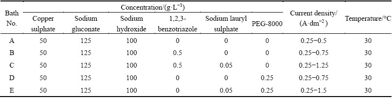
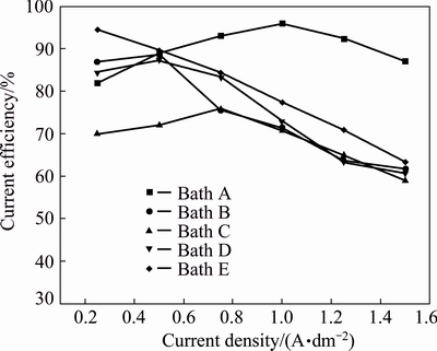
Fig. 1 Current efficiencies obtained from different copper electrolytes at various current densities and 30 °C
The results of electrolyte B (bath B) containing 0.5 g/L of 1,2,3-benzotriazole as additive exhibit that the current efficiency increases up to current density of 0.75 A/dm2 and then steeply decreases with increasing current density. Hydrogen evolution side reaction for all aqueous plating solutions occurs at the cathode, which surpasses the cathode current efficiency to decrease. This could be attributed to the fact that Cu2+ ions form complex with benzotriazole molecules and consequently decrease the current efficiency as well as the simultaneous hydrogen evolution reaction. Therefore, the reduction of the copper complex is not as easy as the reduction of free Cu2+ ions. Hence, it suggests that current density of 0.25-0.75 A/dm2 was optimum for producing a smooth uniform bright deposit with appreciable current efficiency. Latter, the deposit becomes semibright and no evidence for dull and powdery deposit. But the current efficiency and rate of deposition are lower as compared to the additive-free bath A (Fig. 2, bath B). Hence, it can be attributed to the fact that this additive is adsorbed on the electrode surface and thereby blocking the electrode.
With the combination of 0.5 g/L of 1,2,3- benzotriazole and sodium lauryl sulphate 0.05 g/L as additives in bath C, both current efficiency and rate of deposition are still lower as compared to baths A and B (Fig. 2, bath C). It is observed that current density of 0.25-1.25 A/dm2 is optimum for producing a smooth uniform bright deposit. Thereafter, the deposit becomes only semibright and no evidence for dull and powdery deposit.
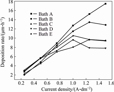
Fig. 2 Rate of deposition obtained from different copper electrolytes at various current densities and 30 °C
The results of bath D containing 0.5 g/L of polyethlyeneglycol-8000 as additive exhibit that the current efficiency steeply decreases with increasing current densities. It is observed that current density of 0.25-0.75 A/dm2 is optimum for producing a smooth uniform bright deposit. Latter, the deposit becomes streaky and nodular form. This could be attributed to the increase in the overpotential of the electrodeposits.
With the combination of 0.25 g/L of PEG-8000 and lauryl sulphate 0.05 g/L as additives in bath E, both current efficiency and rate of deposition steadily decrease. But current efficiency increases as compared to all the baths studied (Fig. 2, bath E). It is observed that current density of 0.25-1.5 A/dm2 is optimum for producing a smooth uniform bright deposit and no evidence for dull and powdery deposit. Hence, it suggests that organic additives are adsorbed strongly on the top of the copper crystallites and inhibit the formation of new growth centers.
3.3 Metal distribution of depositing electrolytes
The effect of current density (0.5-4.0 A/dm2) on the throwing power of baths A-E is illustrated in Fig. 3. Throwing power increases with the increase of current density in all baths. In general, additive-free bath A shows high throwing power as compared to the additive-containing baths. It suggests that, gluconate acts as a good complexing agent in the non-cyanide copper plating baths. Generally, additives are preferentially adsorbed onto asperities on the cathode surface, thereby blocking the attachment of metal ions at those sites and favoring growth at other locations, and therefore, current efficiency decreases.
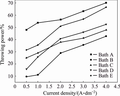
Fig. 3 Effect of current density on throwing power for different copper electrolytes and 30 °C
3.4 Adhesion of copper films
Adhesion of the copper deposits obtained in the presence and absence of additives from the copper bath was tested by subjecting the plated specimens to standard bend tests as per American Society for Testing and Materials Test Method 571-84. The deposits from all five baths were found to withstand the bend test, showing that the keying of the deposit to the base metal is very good in all cases. Hence, the deposits obtained from all five baths are good adherent to the base metal.
3.5 Phase and crystal structure of copper films
The X-ray diffraction patterns of electrodeposited copper films on mild steel foil without any additives from bath A at various current densities (0.25-1.0 A/dm2) and 30 °C are shown in Fig. 4. It can be seen Fig. 4(a) that, three diffraction peaks at 2θ values of 43.39°, 44.57° and 51.99° correspond to (111), (220) and (112) planes of face-centered cubic (FCC) crystal lattice of Cu and CuO, respectively, whereas the intensity of (111) plane is more predominant as compared to those of other peaks. This could be attributed to the lower surface energy of the (111) plane aligned parallel to the surface. This result is in good agreement with standard diffraction data from JCPDS cards No. 85-1326 and 80-1917 for Cu and CuO, respectively. The average copper crystallite size was calculated using Debye-Scherrer equation. At 0.25 A/dm2 (Fig. 4(a)), a comparatively large grain size (64 nm) was produced. Moreover, the relative intensity of (111) copper crystallographic plane showed the highest reflection and the deposit was produced at 0.5 A/dm2, but the crystal size was significantly down to 39 nm (Fig. 4(b)); whereas the crystallographic peak intensity of (112) CuO plane was significantly increased and the deposits were more polycrystalline. This apparently indicates that high current densities give rise to a high degree of adatoms saturation on the electrode surface. This caused the decrease in grain size.
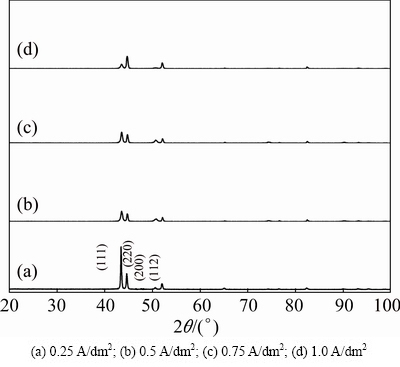
Fig. 4 XRD patterns of copper deposits obtained from electrolyte A at various current densities and 30 °C
Figure 4(c) shows the X-ray diffraction pattern of the electrodeposited copper film produced from the same electrolyte at 0.75 A/dm2 and 30 °C. On the other hand, the intensity of (112) CuO plane still increases and the crystal size reduces to 28.44 nm. Figure 4(d) shows the X-ray diffraction pattern of the electrodeposited copper film produced from the same electrolyte at 1.0 A/dm2 and 30 °C. In this case, the (220) plane crystallographic reflection is more predominant than that of other planes and the relative intensity of (111) pane is suppressed. In the meantime, the intensity of (112) CuO plane still increases and the crystal size reduces to 25.59 nm. Sequentially, increasing current density from 0.25 to 1.0 A/dm2 (Figs. 4(a)-(d)) results in a progressive reduction in the grain size of the deposits down to a grain size of (64-25.6 nm). Hence, a large cathodic over- potential reduces the energy of nucleus formation, and therefore increases the nucleus densities and reduces the grain size of the deposit. It is also the evidence for the fact that intensity of (112) increases with increasing current densities.
X-ray diffraction patterns of electrodeposited copper film on mild steel foil in the presence of various additives from different baths of B, C, D and E at 30 °C are given in Figs. 5(a)-(d), respectively. Figure 5(a) represents the deposit produced from bath B containing benzotriazole additive at 0.5 A/dm2 and 30 °C. In this case, both (111) and (220) crystallographic planes have the highest reflection as compared to the others. The twinning crystals are common for the FCC metals and their alloys in which the electrolyte reduces the stacking fault energy of the solvent. The crystal size of copper film is significantly reduced as compared to that of the additive-free copper film, which influences the adsorption of benzotriazole on the electrode surface and inhibits the deposition rate, which leads to increasing the cathodic overpotential. Figure 5(b) represents the deposit produced from bath C containing benzotriazole and sodium lauryl sulphate (surfactant) at 0.5 A/dm2 and 30 °C. In this case, (220) crystallographic plane has the highest reflection as compared to the others. The combination of benzotriazole (additive) and sodium lauryl sulphate (surfactant) still reduces the grain size of copper film. It could be attributed to the predominant influence of adsorption that causes the reduction in the growth of adatom clusters developing on the cathode, while lowering the rate of growth process and raising the deposition overpotential. Figure 5(c) represents the deposit produced from bath D containing polyethylene glycol additive at 0.5 A/dm2 and 30 °C. In this case, both (111) and (220) are predominant. The result is very similar to the deposit produced from bath B. Figure 5(d) represents the deposit produced from bath E containing polyethylene glycol and sodium lauryl sulphate at 0.5 A/dm2 and 30 °C. In this case, only (220) plane exhibits the high reflection and there is no evidence for (111) and (200) planes and there is no remarkable change in the crystal size.
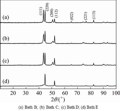
Fig. 5 XRD patterns of copper deposits obtained from different electrolytes at 0.5 A/dm2 and 30 °C
3.6 Texture coefficient of copper films
The diffractograms of copper deposits produced in the absence and presence of additives are displayed in Figs. 4 and 5, respectively, and texture coefficients are recorded in Table 2. The results disclose that the texture coefficient Tc increases with increasing current densities. The increase in preferred orientation is attributed to the increased number of grains along the plane. Moreover, increasing the current density alters the crystallographic orientation from (111) to (220) plane. It is attributed to the overpotential associated with high current densities. Tc increases in the presence of additives even though the use of additives affects the electrocrystallization process with a consequence of altered deposit texture. This indicates that these additives favor parallel growth of the surface. Hence, it apparently discloses that the (220) plane exhibits higher Tc than (111) plane.
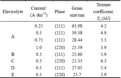
Table 2 Grain size and texture coefficient of copper films obtained from various electrolytes
3.7 Grain size effect
The grain size was calculated using Debye-Scherrer formula and the grain size data are listed in Table 2. From Table 2, we may see that the current density increases with reduction of grain size, which apparently indicates that high current densities give rise to a high degree of adatoms saturation on the electrode surface. This brings about the decrease in grain size. Moreover, the grain size decreases with increasing the Tc values. Similarly, the deposits obtained in the presence of additives exhibit the reduction of grain size and Tc values increase. Hence, the additive increases cathodic over-potential, reduces the energy of nucleus formation, and therefore increases the nucleus densities and reduces the grain size of the deposit.
3.8 Microstructure of copper films
Figure 6 shows the SEM images of the electrodeposited copper films on mild steel foil produced at 0.25, 0.5, 0.75 and 1.0 A/dm2, respectively. A slight variation of surface morphological features is obtained with increasing current density. In Fig. 6(a), it can be seen that a homogeneous nodular deposit is obtained at low current density of 0.25 A/dm2, and when the current density increases, the deposits gradually vary from coarse grain to fine grain morphology (Figs. 6(b)-(d)). Moreover, the electrodeposited copper favors (111) texture orientation. At high current densities, massive nucleation is the predominant effect, thus giving rise to small size and dense grains, compact morphology, thus promoting the formation of nuclei instead of the growth of crystals. On the other hand, at very high current densities, electrodeposited copper films become mass transfer limited or very close the mass transfer limited. Whenever this happens, the deposits become dendrites and powdery.
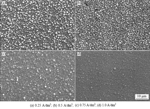
Fig. 6 SEM images of copper deposits obtained from bath A at various current densities and 30 °C

Fig. 7 SEM images of copper deposits obtained from different electrolytes at 0.5 A/dm2 and 30 °C
Figures 7(a)-(d) show the SEM images of the electrodeposited copper films on mild steel foil produced at 0.5 A/dm2 from different baths B, C, D and E, respectively. Figure 7(a) indicates copper film prepared from bath B containing 0.5 g/L benzotriazole at 30 °C. There is a noticeablly different surface morphology which is noticed with the addition of additive. As exhibited in Fig. 7(a), copper film produces a structure with a large number of very small grains uniformly distributed throughout the crystal lattice and there is no evidence of any nodules. The same type of SEM image was also reported by TANTAVICHET and PRITZKER [41]. Benzotrizaole may be adsorbed on the copper surface due to a relatively uniform surface energy distribution. Hence, there are less preferential active sites available for deposition. The comparison of Figs. 6(a) and 7(a) displays the remarkable change in deposit quality achieved by the addition of benzotriazole alone. Figure 7(b) represents that copper film obtained from bath C containing both 0.5 and 0.05 g/L benzotriazole at 30 °C. A significant change is observed in the surface morphology. Moreover, it can be observed that in the SEM image of copper films, more large number of tiny grains are uniformly arranged in the crystal lattice. Sodium lauryl sulphate (SLS) alters the over-potential, thereby changing the quality of the copper film and becoming smooth, dense and fine surface morphology. Hence, SLS may act as an inhibitor. The comparison of Figs. 7(a) and (b) exhibits the marked change in deposit quality improved by the introduction of benzotriazole (BTA) and sodium lauryl sulphate combination. Figure 7(c) exhibits that copper film prepared from bath D containing 0.5 g/L PEG at 30 °C. From Fig. 7(c), it can be seen that for the copper film prepared from the solution containing PEG alone, a peculiar type of surface morphology is formed, apart from growth features due to nodulation. The similar morphology was also investigated by VICENZA and CAVALLOTTI [27]. During the electrodeposition, PEG molecules are adsorbed at the electrode and inhibit metal deposition. Figure 7(d) shows that copper film prepared from bath containing 0.5 g/L PEG and 0.05 g/L SLS at 30 °C. From Fig. 7(d), it is observed that, the copper film is obtained from bath E containing the combination of PEG and SLS. The surface morphology is still modified and the copper film becomes smooth and fine grained surface morphology. Hence, both PEG and SLS molecules inhibit the metal deposition.
3.9 Morphology of copper films
The AFM images of copper deposits obtained in the absence and presence of additives are displayed in Figs. 8 and 9, respectively. Figure 8(a) represents AFM images of copper deposit produced from bath A at 0.25 A/dm2. From Fig. 8(a), we may see that some inhomogeneous copper islands are located mostly along grain boundaries and the deposit is rough. The average roughness Ra is 58.5 nm. When the current density increases to 0.5 A/dm2 in the same bah (Fig. 8(b)), some minor variations are observed in the deposit morphology. Moreover, the grain size and surface roughness are also marginally reduced (Ra=48.3 nm). Similarly, the current density increases to 0.75 A/dm2 in Fig. 8(c), and the surface morphology of the deposit is still improved. The grain size and surface roughness values are significantly reduced to 39.4 nm. Figure 8(d) shows AFM image of copper deposit prepared at 1.0 A/dm2 in the same bath, indicating that a smoother deposit is produced by increasing the current density and a drastic reduction of grain size and surface roughness is observed (Ra=26.6 nm).
Figure 9(a) indicates AFM image of copper deposits obtained from bath B containing benzotriazole at 0.5 A/dm2 and 30 °C. From this image, we may observe that a large number of homogeneous copper hills are uniformly covered over the entire area of the surface. On the other hand, the grain size and roughness of copper deposit are significantly reduced (Ra=13.7 nm). Conversely, benzotriazole-containing bath yields smooth and almost featureless deposits irrespective of the current density, indicating a decrease in surface roughness. Figure 9(b) shows AFM image of copper deposits obtained from bath C containing the combination of benzotriazole and sodium lauryl sulphate under similar conditions. A smooth uniform fine grain with a different flat surface morphology is obtained. In this case, deposits were crack-free and pitting was not observed, probably due to the anti-pitting effect caused by the sodium lauryl sulphate (SLS) wetting agent [42]. The grain size, surface morphology and surface roughness (Ra=4.07 nm) were also remarkably reduced. Figure 9(c) represents AFM image of copper deposits obtained from bath D containing PEG-8000, exhibiting small hills like surface morphology and the deposits containing some pores. This may be due to hydrogen bubbles accumulated in the deposits. Although grain size and roughness value (Ra=16.9 nm) of copper deposits were reduced, bath E containing PEG-8000 and sodium lauryl sulphate showed different surface morphologies. On the other hand, the grain size and surface roughness of deposits remarkably were reduced (Ra=5.27 nm). Hence, SLS may act as a hydrogen suppressor. This apparently indicates that the combination of additives reduces the grain and roughness of the deposits. Among these additives studied, the mixture of benzotriazole and sodium lauryl sulphate acts as the best grain refiner.

Fig. 8 AFM images of copper deposits obtained from electrolyte A at various current densities and 30 °C
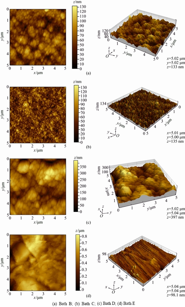
Fig. 9 AFM images of copper deposits obtained from different electrolytes at 0.5 A/dm2 and 30 °C
4 Conclusions
Adherent and smooth copper deposits were plated on mild steel metallic foils from non-cyanide copper electrolytes with high current efficiency and good throwing power. X-ray diffraction studies revealed that deposits obtained from all electrolytes exhibited the highest reflection of (111) plane. The deposits produced by the combination of additives containing electrolytes displayed the highest reflection of (220) plane. The crystal size calculation based on XRD data revealed that the deposit obtained from the combination of additives containing electrolytes showed the smallest crystal size as compared to single additive containing electrolytes. Texture coefficient studies revealed that the deposits yielded from additives containing electrolytes showed higher value. SEM images showed that the deposits obtained in the absence of additives exhibited homogeneous nodular deposits, whereas the deposits produced in the presence of additives containing electrolytes have smooth, compact, fine and pore-free structure. AFM studies revealed that deposits prepared without adding additives exhibited hill-like morphology, whereas the deposits produced in the presence of additive showed flat morphology. Hence, the combination of benzotriazole and sodium lauryl sulphate acted as the best grain refining agent for copper deposits.
References
[1] OSKAM C, VEREECKEN P M, SEARSON P C. Electrochemical deposition of copper on n-Si/TiN [J]. Journal of the Electrochemical Society, 1999, 146: 1436-1441.
[2] HU C C, WU C W. Effect of deposition modes on the microstructure of copper deposits from an acidic sulphate bath [J]. Surface and Coatings Technology, 2003, 176: 75-83.
[3] GRUJICIE D, PESIC B. Electrodeposition of copper: The nucleation mechanisms [J]. Electrochim Acta, 2002, 47: 2901-2912.
[4] WAN C, LEI J, BJELKEVOG C, RUDENJA S, MAGTOTO N, KELBER J. Electrodeposition of adherent copper films on unmodified tungsten [J]. Thin Solid Films, 2003, 445: 72-79.
[5] SEAH C H, MRDHA S, CHAN L H. DC/pulse plating of copper for Trench/via filling [J]. Journal of Materials Process and Technology, 2001, 114: 233-239.
[6] BALASUBRAMANIAN A, SRIKUMAR D S, RAJA G, SARAVANAN G, MOHAN S. Effect of pulse electrodeposition of copper on stainless steel [J]. Surface Engineering, 2009, 25: 389-392.
[7] MANTRY S, BEHERA D, SATAPATHY A, JHA B B, MISHRA B K. Deposition of plasma sprayed copper slag coatings on metal substrates [J]. Surface Engineering, 2003, 29: 222-227.
[8] ZHU P, WANG L Y, CHEN Y, ZHOU M, ZHOU J. Electrodeposition of copper coating on AZ31 magnesium alloy [J]. Surface Engineering, 2012, 28: 796-799.
[9] SEKAR R, JAGADESH K K, RAMESH BAPU G N K. Electrodeposition and characterization of copper deposits from non-cyanide electrolytes [J]. Surface Engineering, 2015, 31: 433-438.
[10] PAK J H, KIM G N, HWANG S G, KIM B S, NOH J P, HUH S C. Mechanical properties of Cu matrix composite fabricated by extrusion process [J]. Transactions of Nonferrous Metals Society of China, 2016, 26: 2679-2686.
[11] CAI A H, LIU Y, WU H, DING D W, AN W K, ZHOU G J, LUO Y, PENG Y Y, LI X S. Effect of aspect ratio and loading rate on room-temperature mechanical properties of Cu-based metallic glasses [J]. Transactions of Nonferrous Metals Society of China, 2016, 26: 2617-2632.
[12] SEKAR R, JAGADESH K K, RAMESH BAPU G N K, Autocatalytic deposition of copper from modified electrolytes and its characterization [J]. Transactions of Nonferrous Metals Society of China, 2015, 25: 3791-3801.
[13] JAIN S, JAIN A, KACHHAWAH P, DEVRA V. Synthesis and size control of copper nanoparticles and their catalytic application [J]. Transactions of Nonferrous Metals Society of China, 2015, 25: 3995-4000.
[14] TRASATTI S. Adsorption of organic substrates at electrode: Recent advances [J]. Electrochim Acta, 1992, 37: 2137-2144.
[15] ONICIU L, MURESAN L. Some fundamental aspects of levelling and brightening in metal electrodeposition [J]. Journal of Applied Electrochemistry, 1991, 21: 565-574.
[16] PLIETH W. Additives in the electrocrystallization process [J]. Electrochim Acta, 1992, 37: 2115-2121.
[17] QUINET M, LALLEMAND F, RICQ L, HIHU J Y, DELOBELLE P, ARNOULD C, MEKHALIF Z. Influence of organic additives on the initial stages of copper electrodeposition on polycrystalline platinum [J]. Electrochim Acta, 2009, 45: 1529-1536.
[18] TANTAVICHET N, DAMRONGLERD S, CHAILAPAKUL O. Influence of the interaction between chloride and thiourea on copper electrodeposition [J]. Electrochim Acta, 2009, 55: 240-249.
[19] MIRKOVA L, PETKOVA N, POPOVA I, RASHKOV S T. The effect of some surface active additives upon the quality of cathodic copper deposits during the electrorefining process [J]. Hydrometallurgy, 1994, 36: 201-213.
[20] WU A, BARKEY D P. Pattern recognition and scaling studies of copper electrodeposition on Cu (100) in the presence of additives [J]. Journal of the Electrochemical Society, 2003, 150: C533-C537.
[21] ALLAM N K, NAZEER A A, ASHOUR E A. A review of the effects of benzotriazole on the corrosion of copper alloys in clean and polluted environments [J]. Journal of Applied Electrochemistry, 2009, 39: 961-969.
[22] BOZZINI B, MELE C, D’URZO L D, GIOVANNELLI G, NATALI S. Electrodeposition of Cu from acidic sulphate solutions in the presence of PEG: An electrochemical and spectrochemical investigation [J]. Journal of Applied Electrochemistry, 2006, 36: 789-800.
[23] OISHI T, YAGUCHI M, KOYAMA K TANAKA M, LEE J C. Effect of additives on monovalent copper electrodeposition in ammonical alkaline solutions [J]. Hydrometallurgy, 2013, 133: 58-63.
[24] SCHLESINGER M, PAUNOVIC M. Modern electroplating [M]. 4th ed. New York: John Wiley& Sons Inc, 2000.
[25] BALLESTEROS J B, CHAINET E, OZIL P, TREJO G, MEAS Y. Initial stages of the electrocrystallization of copper from non-cyanide alkaline bath containing glycine [J]. Journal of Electroanalytical Chemistry, 2010, 645: 94-102.
[26] RODE S, HENNINOT C, VALLIERS C, MATLOSZ M. Complexation chemistry in copper plating from citrate baths [J]. Journal of the Electrochemical Society, 2004, 151: C405-C411.
[27] VICENZA A, CAVALLOTTI P L. Copper electrodeposition from a pH3 sulphate electrolyte [J]. Journal of Applied Electrochemistry, 2002, 32: 743-753.
[28] FENG S B, SHANG S B. Direct plating of steel with pyrophosphate copper [J]. Plating and Surface Finishing, 2005, 92: 38-41.
[29] THARAMANI C N, MARUTHI B N MAYANNA S M. Development of a non-cyanide alkaline bath for industrial copper plating [J]. Transactions of Institute of Metal Finishing, 2002, 80: 37-39.
[30] MATSUOKA M, MURAI J, IWAKURA C. Kinetics of electroless copper plating and mechanical properties of deposits [J]. Journal of the Electrochemical Society, 1992, 139: 2466-2470.
[31] RAFIZADEH M, BAHMANI M, CHELARAS R T. New alkaline copper electroplating bath based on an inorganic complexing agent [J]. Portugaliae Electrochimica Acta, 2006, 24: 387-392.
[32] SEKAR R, SOBHA J. Electrodeposition of zinc from acetate baths [J]. Plating and Surface Finishing, 2005, 92: 58-67.
[33] SEKAR R, SOBHA J. Characteristics of zinc electrodeposits from acetate solutions [J]. Journal of Applied Electrochemistry, 2006, 36: 591-597.
[34] SEKAR R, EAGAMMAI C, SOBHA J. Effect of additives on electrodeposition of tin and its structural and corrosion behaviour [J]. Journal of Applied Electrochemistry, 2010, 57: 49-57.
[35] SEKAR R, JAYAKRISHNAN S. Effect of sulphonic acids on electrodeposition of nickel and its structural and corrosion behaviour [J]. Transactions of Institute of Metal Finishing, 2012, 90: 324-329.
[36] ASTM test method 571-84: Adhesion of metallic coatings [S]. West Conshohocken SATM International, 1995-02-05.
[37] CULLITY B D. Elements of X-ray diffraction [M]. New York: Reading MA Addison Wesley Publishing Company Inc, 1967: 24.
[38] KLUG H P, ALEXANDER L. X-ray diffraction procedures for polycrystalline and amorphous material [M]. New York: Wiley, 1980.
[39] APARICIO J L O, MEAS Y, TREJO G, ORTEGA R, CHAPMAN T W, CHAINET E. Effect of organic additives on zinc electrodeposition from alkaline electrolytes [J]. Journal of Applied Electrochemistry, 2013, 43: 289-300.
[40] NAYANA K O, VENKATESHA T V. Synergistic effects of additives on morphology, texture and discharge mechanism of zinc during electrodeposition [J]. Journal of Electroanalytical Chemistry, 2011, 663: 98-107.
[41] TANTAVICHET N, PRITZKER M. Copper electrodeposition in sulphate solutions in the presence of benotriazole [J]. Journal of Applied Electrochemistry, 2006, 36: 49-61.
[42] MOHANTY U S, TRIPATHY B C, DAS S C, SINGH P, MISRA V V. Effect of sodium lauryl sulphate (SLS) on nickel electrowinning from acidic sulphate solutions [J]. Hydrometallurgy, 2009, 100: 60-64.
R. SEKAR
Electroplating and Metal Finishing Technology Division, Central Electro Chemical Research Institute, Karaikudi 630006, Tamil Nadu, India
摘 要:由于铜在低碳钢上的伽伐尼置换反应,酸性铜板在低碳钢基体上的电沉积比较困难。使用一种适宜的络合剂可解决这一问题,因为络合剂能通过形成配位化合物降低铜的电位。本文作者研究在碱性介质中以葡萄糖酸钠为络合剂从无氰电解质中电沉积铜。考察1,2,3-苯并三唑、十二烷基硫酸钠、聚乙二醇-800和糖精等添加剂对铜电沉积的影响。结果表明,这类添加剂不仅能降低电沉积铜的晶粒尺寸和晶界、改善其表面形貌,而且能提高电解质的均镀能力及电沉积铜的硬度。采用X射线衍射技术(XRD)对沉积铜进行表征。XRD结果表明,电沉积铜为多晶和面心立方结构。利用XRD结合原子力显微镜(AFM)计算电沉积铜的晶粒尺寸。在所研究的添加剂中苯并三唑和十二烷基酸钠混合添加剂的效果最好。用扫描电镜观察到的均匀无孔表面及AFM结果显示,上述添加剂能使电沉积铜的晶粒细化。
关键词:协同效应;葡萄糖酸盐;添加剂;原子力显微镜;电沉积;铜
(Edited by Wei-ping CHEN)
Corresponding author: R. SEKAR; Tel: +91-4565-241572; FAX: +91-4565-7779; E-mail: grsek2004@yahoo.com
DOI: 10.1016/S1003-6326(17)60189-4

