Trans. Nonferrous Met. Soc. China 29(2019) 1873-1881
Mechanism of reheat cracking in electron beam welded Ti2AlNb alloys
Yan-jun LI1,2, Ai-ping WU1,3,4, Quan LI5, Yue ZHAO1,4, Rui-can ZHU5, Guo-qing WANG6
1. Department of Mechanical Engineering, Tsinghua University, Beijing 100084, China;
2. Beijing Institute of Radio Measurement, Beijing 100854, China;
3. State Key Laboratory of Tribology, Tsinghua University, Beijing 100084, China;
4. Key Laboratory for Advanced Materials Processing Technology, Ministry of Education, Tsinghua University, Beijing 100084, China;
5. Capital Aerospace Machinery Company, Beijing 100076, China;
6. China Academy of Launch Vehicle Technology, Beijing 100076, China
Received 27 June 2018; accepted 4 June 2019
Abstract: In order to clarify the characteristics and formation mechanism of the reheat cracking in Ti2AlNb weldments, a series of heat treatment conditions were performed to the circular joints welded by electron beam, and then the macrostructures and microstructures were investigated using optical microscopy, scanning electron microscopy, X-ray diffractometry, and transmission electron microscopy. The results show that the reheat cracking occurs primarily along the grain boundaries in the weld when the Ti2AlNb circular welded joints are heated up to about 700 ��C. During the heat treatment, an almost complete transformation of B2��O happens while the temperature goes up through the O single-phase region. Then, O��B2+O phase transformation occurs primarily along the grain boundaries as the weld metal continues to heat up to the B2+O dual-phase region. Under the high tension stress consisting of welding residual stress and phase transformation stress, reheat cracking occurs at the interface between the B2+O dual-phase layer and the O-phase matrix.
Key words: reheat cracking; electron beam welding; Ti2AlNb alloy; microstructure evolution
1 Introduction
Over the past decades, Ti2AlNb-based alloys have attracted wide attention. The alloys contain a large amount of ordered orthorhombic O phase, which was firstly identified by BANERJEE et al in 1988. In addition of the ordered orthorhombic O (Ti2AlNb) phase, the alloys include ��2 (hexagonal, Ti3Al), and ordered B2 (body-centered cubic) phase as well. Generally, the contents of Al and Nb in the alloys are 22-25 at.% and 20-27 at.%, respectively. Ti-22Al-23Nb (at.%), Ti-22Al-25Nb (at.%), and Ti-22Al-27Nb (at.%) [1,2] are the typical Ti2AlNb alloys. Due to the high specific strength, attractive creep and corrosion resistance, and superior processability, the Ti2AlNb alloys show great potential as structural materials in aerospace and elevated temperature fields [3,4].
To fabricate high-quality joined structures, various welding or joining processes are being developed. The processes to be developed will extend the applications of the Ti2AlNb alloys. Up to now, several welding methods have been studied to investigate the weldabilities of the Ti2AlNb alloys, including diffusion bonding [5], linear friction welding [6,7], laser beam welding (LBW) [8-11] and electron beam welding (EBW) [12-14]. ZOU et al [5] have studied the microstructure and strength of the joints during transient liquid phase diffusion bonding of Ti-22Al-25Nb alloy. CHEN et al [6,7] have investigated the microstructure evolution and mechanical properties of linear friction welded Ti2AlNb alloy under as-welded and post-weld heat treatment conditions. LEI et al [10,11] have investigated the microstructure evolution and tensile properties of laser welded Ti-22Al-27Nb and Ti-22Al-27Nb/TC4 joints, and ZHANG et al [9] have studied the laser weldability of dissimilar Ti-22Al- 27Nb/TA15 alloys. The laser welded joints of this type of alloys showed low ductility at ambient and high temperatures due to the columnar structure during solidification and the O phase precipitated in the B2 grain boundaries in the welds. EBW is preferable to joining titanium alloy, because it has a clean vacuum chamber and high energy density and relatively low heat input [12-14] that produces a weld with narrow and deep penetration, small heat-affected zone, and low distortion and residual stresses. Therefore, EBW has become a preferred method of the Ti2AlNb alloys welding. TAN et al [15,16] have conducted dissimilar welding of Ti-22Al-25Nb and TC11 alloys using EBW. In their studies, hot work, such as isothermal deformation accompanied with heat treatment, has been employed to improve the microstructures and the mechanical properties of the welded joints.
The fusion zone of the EBW welded joint is basically composed of unstable B2 phase due to fast cooling rate and high content of niobium [17]. On the other hand, Ti2AlNb alloy is expected to be used at elevated temperature such as 650 ��C. Therefore, post- weld heat treatment is necessary to optimize the microstructure and enhance the mechanical properties for the welded joints. However, in our preliminary study, serious cracks were observed in the fusion zone as the EBW joints underwent post-weld heat treatment. This cracking can be classified into reheat cracking. The reheat cracking in Ti2AlNb weldments has not been investigated except for a very few preliminary results. CAI et al [18] found cracks in the nugget of Ti2AlNb alloy resistance spot weldments after post-weld heat treatment, and their results indicated that the precipitation of hardening phase (O phase) together with the residual stress led to the cracking during post-weld heat treatment. Nevertheless, the characteristics and formation mechanism of the reheat cracking in Ti2AlNb weldments are not clear up to now.
In this study, a series of post-weld heat treatments were performed to EBW joint of Ti2AlNb alloy in order to figure out the temperature range where reheat cracking happens. The mechanism of the reheat cracking in Ti2AlNb EBW joint was investigated by analyzing the characteristics of the crack and the microstructure evolution during the heat treatment.
2 Experimental
2.1 Material and welding process
The base metal used in this study was hot-rolled Ti-22Al-25Nb sheet with the thickness of 5 mm. The nominal composition of the material is 22 at.% Al, 25 at.% Nb and balanced Ti. It was provided by Central Iron and Steel Research Institute, China. The specimens were cut from the sheet into 50 mm �� 50 mm coupons. Before EBW, the oxide layer was removed from the surfaces with specific acid solution (3 mL HF, 30 mL HNO3 and 67 mL H2O). And then, the specimens were cleaned with acetone and then dried. The bead-on-plate circular seam welds were made using GENOVA 98 model EBW machine. A schematic diagram of welding process can be seen in Fig. 1. The welding condition is given in Table 1.

Fig. 1 Schematic diagram of welding process
Table 1 Welding condition

2.2 Post-weld heat treatment
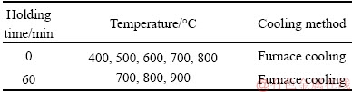
Previous investigations [6,17] showed that heat treatment in the temperature range of 750-900 ��C was often performed to Ti2AlNb welded joints in order to improve the tensile properties, and the holding time was usually 1-2 h. To investigate the reheat cracking of the Ti2AlNb EBW joint, various heat treatments were conducted in this study, as given in Table 2. Holding time of 0 min means that the specimen was heated up to the selected temperature and then cooled down immediately. The heat treatments with holding time of 0 min at 400, 500, 600, 700 ��C were carried out in a resistor furnace with a heating rate of 10 ��C/min, while the others were treated in a vacuum furnace with a heating rate of 20 ��C/min. After that, the specimens were examined to check whether there were cracks or not.
Table 2 Heat treatment parameters
2.3 Microstructure characterization
After the welded joints were heat-treated, metallographic specimens were cut from the joints at the representative positions: the steady welding region and ending region, as shown in Fig. 2. And then, conventional titanium metallographic procedures were used to prepare the metallographic specimens. After mounting, grinding and polishing, the specimens were etched using a special reagent (10 mL HF, 30 mL HNO3 and 50 mL H2O2). The reheat cracks of welded joints were observed using an OLYMPUS BX 51M optical microscope. The microstructures of the joints were observed with a ZEISS Supra 55 scanning electron microscopy (SEM). X-ray diffraction (XRD) was used to identify the phase composition of the weld metal. A slice sample was cut out of the weld zone, mechanically polished and ion-thinned for transmission electron microscopy analysis (TEM, Tecnai G2 F20 S-TWIN).
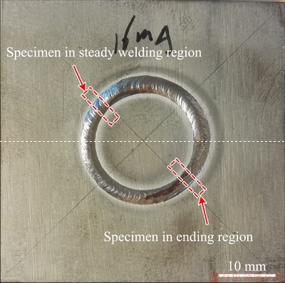
Fig. 2 Schematic diagram of sampling locations
3 Results and discussion
3.1 Effects of heat treatment condition on occurrence of reheat cracking
The cross-sectional macrostructures of the as-welded sample and the heat-treated samples with common heat treatment parameters (700-900 ��C, 60 min) were examined at first. As shown in Fig. 3(a), no crack was observed within the fusion zone of the as-welded sample. However, after the samples were heat-treated at 700-900 ��C for 60 min, cracking obviously occurred in the samples, as illustrated in Figs. 3(b-d). The cracks were observed both in the steady welding region and ending region. And the cracks were mainly located in the fusion zone. The results indicate that reheat cracking easily occurs in the fusion zone when the common post-weld heat treatments are performed to the Ti2AlNb EBW joint.
The above results show that obvious cracking occurred in the Ti2AlNb EBW joints after they were heat treated at high temperature for 60 min. To make clear the stage where the crack happened, the joint was heated up to 800 ��C and cooled down immediately, and then, the joint was examined to check whether there were cracks or not. As shown in Fig. 4(a), obvious reheat cracks were still observed in the fusion zone even though the joint was cooled down immediately from 800 ��C. This means that the reheat cracking happened in the heating-up period. To further clarify the temperature range where the crack happened, the Ti2AlNb EBW joints were heated up to 400, 500, 600, 700 ��C, respectively, and cooled down immediately. And then, the corresponding cross-sectional macrostructures of the joints were inspected. As shown in Figs. 4(b-e), no cracking occurred in the joints heat-treated below 600 ��C, while obvious cracking occurred in the fusion zone of the joints heat-treated above 700 ��C. Thus, we can conclude that it is in the heating-up process that the reheat-cracking happens as Ti2AlNb EBW joints are heated to around 700 ��C.

Fig. 3 Macrostructures in fusion zone of Ti2AlNb EBW joints heat-treated for 60 min
3.2 Intergranular feature of reheat cracking
The reheat cracking occurred intergranularly, as shown in Fig. 5. In order to further observe the intergranular cracking, high magnification morphologies for grain boundary (GB) of the fusion zone in as-welded samples and the heat-treated samples were obtained by means of SEM. Figure 6(a) shows SEM image of as-welded samples, indicating that no intergranular precipitation generated along GB in the fusion zone. As shown in Figs. 6(b-d), when the temperature was sufficiently low, such as below 600 ��C, the GBs in the fusion zone of the heat-treated samples were almost the same as those of as-welded samples, and no intergranular precipitation was found. On the other hand, when the temperature was increased to 700 ��C, a thin precipitation layer distinct from the adjacent matrix formed at the original GB. And the thickness of the precipitation layer increased as the temperature was increased to 800 ��C. Figure 7 shows the micro-crack at original grain boundary of the sample heat-treated at 800 ��C, indicating that the reheat cracking actually initiated and propagated along the interface between the precipitation layer and the matrix.

Fig. 4 Macrostructures in fusion zone of Ti2AlNb EBW joints heated to different temperatures with holding time of 0 min
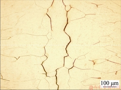
Fig. 5 intergranular characteristic of reheat cracking of sample (700 ��C, 60 min)
3.3 Metallurgical factor affecting reheat cracking
Microstructure evolutions were investigated to clarify the metallurgical factor responsible for the reheat cracking. The XRD pattern in Fig. 8(a) shows that the weld metal of the Ti2AlNb EBW joints mainly consisted of B2 phase, and the low relative peak intensity of O phase indicated the quantity of O phase was very small. It has been reported that, the as-welded Ti2AlNb is almost composed of B2 phase due to the high niobium content in Ti2AlNb alloys and the fast cooling rate of welding process [17]. Figure 8(b) displays the diffraction patterns of the weld metal under different heat treatment conditions. As illustrated, the weld metal of the Ti2AlNb joints was still predominantly composed of B2 phase while the temperature was below 600 ��C. Meanwhile, the relative peak intensity of O phase increased slightly with the increase of temperature, which indicated that the phase transformation B2��O had happened. As the temperature was increased above 700 ��C, the relative peak intensity of B2 phase decreased significantly to a very low level, which means that an almost complete transformation of the B2 phase to the O phase had taken place, and the Ti2AlNb joints was then mainly composed of O phase.
To further characterize the phase composition in the weld metal, especially in the vicinity of GB, TEM examination was performed on this region under as-welded condition and (800 ��C, 0 min) heat treatment condition. A bright-field image of the weld metal under as-welded condition is shown in Fig. 9(a). The selected area electron diffraction (SAED) from area in the red ring was accordance with the patterns corresponding to B2 (Fig. 9(b)), and no other diffraction patterns corresponding to ��2 or O were found. However, a quite different phase composition was found in the weld metal under (800 ��C, 0 min) heat treatment condition, as shown in Fig. 10. The SAED patterns in Figs. 10(b) and (d) show that the B2 phase in the weld matrix transformed to O phase. According to the above results, a thin precipitation layer formed along the original GB in the weld metal when the temperature was increased above 700 ��C. The precipitation layer was also observed by TEM, as shown in Fig. 10(a). The SAED pattern in Fig. 10(c) shows that the precipitation layer was composed of O+B2 dual phases, and the orientation relationship between the O phase and B2 phase was (001)O//(110)B2 and  //
// .
.
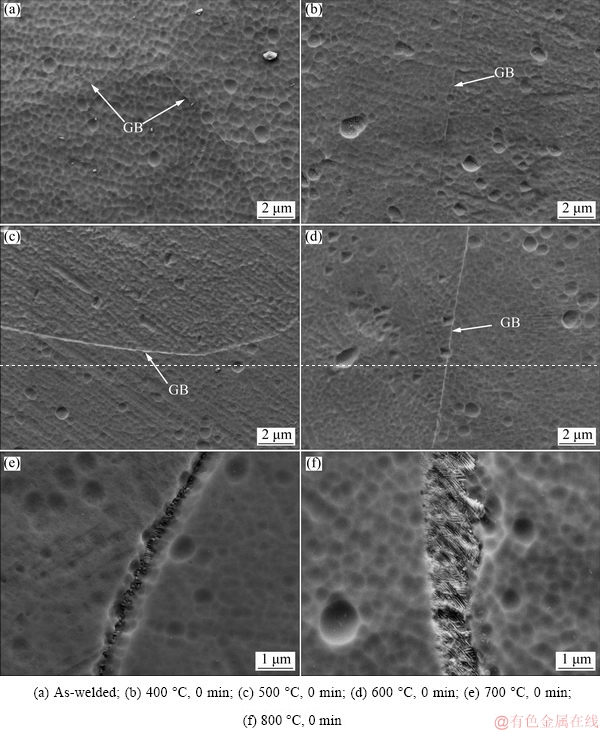
Fig. 6 SEM images of grain boundary

Fig. 7 Micro-crack at original grain boundary of sample (800 ��C, 0 min)
Figure 11 shows phase diagram of Ti-22Al-xNb (at.%) [19]. Combining the phase diagram and the above microstructure examination results, the microstructure evolution of the weld metal during the heating-up process can be better analyzed. As shown in Fig. 11, the O single-phase region of Ti-22Al-25Nb (at.%) is below around 640 ��C, and the B2+O dual-phase region of this alloy is about 640-900 ��C. As the Ti2AlNb welded joint is heated up through the O single-phase region, the B2 phase in the weld metal transforms to O phase entirely. This transformation has been observed by MURALEEDHARAN et al [20,21] in the Ti-24Al- 15Nb (at.%) alloy, and demonstrated to be a massive transformation by a shearing mechanism, without change in composition. As the temperature continues to increase in the B2+O dual-phase region, the O product can decompose to B2+O dual-phase microstructure, and the orientation relationship is (001)O//(110)B2 and //. The O��B2+O phase transformation is prone to occur at grain boundary, resulting in a thin precipitation layer composed of B2+O dual-phase at the original GB. Compared with the interiors of crystals, grain boundaries exhibit higher energy due to many crystal defects such as vacancies and dislocations. Moreover, grain boundaries provide high diffusivity (��short-circuit��) paths leading to faster diffusion of the solute atoms along the grain boundaries. Therefore, grain boundaries meet the thermodynamic and kinetic criteria for the nucleation and growth of new phase, resulting in the phase transformation occurring primarily along the grain boundaries. There are significant differences between the fully-O microstructure and the O+B2 dual-phase microstructure on structure and mechanical properties [22]. As a consequence, stress-concentration probably happens at the interface between the O-phase matrix and the B2+O dual-phase layer, resulting in the interfacial stress exceeding the interfacial strength, and thus cracking happens. This has been demonstrated by the fact that reheat cracking occurred along the interface between the precipitation layer and the matrix, as shown in Fig. 7. To summarize, the B2+O dual-phase layer, inducing stress-concentration, is a key factor responsible for the reheat cracking.
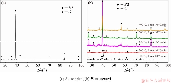
Fig. 8 XRD patterns of weld metal
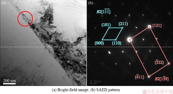
Fig. 9 TEM images of weld metal under as-welded condition
3.4 Stress factor affecting reheat cracking

Fig. 10 TEM images of weld metal under (800 ��C, 0 min) heat treatment condition
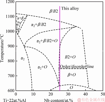
Fig. 11 Phase diagram of Ti-22Al-xNb alloys [19]
The B2+O dual-phase layer has been demonstrated to be a key factor for the reheat cracking. However, the reheat cracking was observed in the above circular weldment but not in straight weldment with the same post-weld heat treatment, as shown Fig. 12. The microstructures of the circular and straight weldments were mainly composed of B2 phase, but the stress levels were different for them. In this work, the residual stress distributions in the welding were investigated using numerical simulation method. And the details of thermo-elastic-plastic finite element analysis have been introduced in our previous work [23]. As the large reheat cracks were generally along the weld centerline, the stresses perpendicular to the weld bead of these two kinds of joints were compared. As shown in Fig. 13, the radial stress level of the circular weldment was much higher than the transverse stress level of the straight weldment, and the maximum stress values were 744 and 241 MPa, respectively. The fusion zone of the circular weldment was supposed to endure a stronger restraint than that of the straight weldment, leading to a higher stress level in the circular weldment. Therefore, we consider that the residual stress produced during welding is another necessary factor for the reheat cracking. In addition, the phase transformations may also produce some stress. Under the high tension stress consisting of welding residual stress and phase transformation stress, the interfacial stress exceeds the interfacial strength, and reheat cracking occurs at the interface between the B2+O dual-phase layer and the O-phase matrix.

Fig. 12 Macrostructure of straight weld after heat treatment (800 ��C, 0 min, 20 ��C/min)
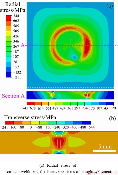
Fig. 13 Residual stress distributions
3.5 Discussion
The weld metal of the Ti2AlNb EBW joints mainly consists of B2 phase, and endured high welding residual stresses. During the post weld heat treatment, an almost complete transformation of the B2 phase to the O phase happens while the temperature goes up through the O single-phase region. The phase transformation of B2��O is a massive transformation by a shearing mechanism, without change in composition. The O product is metastable, and it subsequently decomposes to B2+O as the weld metal continues to heat up to the B2+O dual-phase region, which is about 640-900 ��C. Since the grain boundaries meet the thermodynamic and kinetic criteria for the nucleation and growth of new phase, the O��B2+O phase transformation occurs primarily along the grain boundaries. A thin precipitation layer composed of B2+O dual-phase forms at the original GB due to the O��B2+O phase transformation. The interface between the O-phase matrix and the B2+O dual-phase layer is the weak site because of the significant differences between the fully-O microstructure and the O+B2 dual-phase microstructure on structure and mechanical properties. Under the high tension stress consisting of welding residual stress and phase transformation stress, reheat cracking occurs at the interface between the B2+O dual-phase layer and the O-phase matrix. In a word, the B2+O dual-phase layer forming at the original grain boundary together with the high residual stress leads to the reheat cracking during the post-weld heating process in EBW weldments of Ti2AlNb alloy.
4 Conclusions
(1) Reheat cracking easily occurs in the fusion zone when the common post-weld heat treatments are performed to the Ti2AlNb EBW joint. And it is in the heating-up process that the cracks happen as the temperature is increased to around 700 ��C.
(2) As the temperature is increased to about 700 ��C, the B2 phase in fusion zone transforms to O phase entirely and then a B2+O dual-phase layer forms at the original grain boundary. The orientation relationship of the dual-phase structure is (001)O//(110)B2 and // .
.
(3) Stress concentration is probably induced by the significant differences between full O microstructure and O+B2 dual-phase microstructure on structure and mechanical properties. Under the high tension stress consisting of welding residual stress and phase transformation stress, the interfacial stress exceeds the interfacial strength, and thus reheat cracking occurs at the interface between the B2+O dual-phase layer and the O-phase matrix.
References
[1] DANG W, LI J S, ZHANG T B, KOU H C. Microstructure and phase transformation in Ti-22Al-(27-x)Nb-xZr alloys during continuous heating [J]. Journal of Materials Engineering and Performance, 2015, 24(10): 3951-3957.
[2] CHEN W, LI J W, XU L, LU B. Development of Ti2AINb alloys: Opportunities and challenges [J]. Advanced Materials & Processes, 2014, 172(5): 23-27.
[3] JIA J B, ZHANG K F, LIU L M, WU F Y. Hot deformation behavior and processing map of a powder metallurgy Ti-22Al-25Nb alloy [J]. Journal of Alloys and Compounds, 2014, 600: 215-221.
[4] KUMPFERT J, LEYENS C. Orthorhombic titanium aluminides: Intermetallics with improved damage tolerance [M]// LEYENS C, PETERS M, ed. Titanium and Titanium Alloys: Fundamentals and Applications. Wiley-VCH Verlag GmbH & Co, 2003: 59-88.
[5] ZOU G S, XIE E H, BAI H L, WU A P, WANG Q, REN J L. A study on transient liquid phase diffusion bonding of Ti-22Al-25Nb alloy [J]. Materials Science and Engineering A, 2009, 499(1-2): 101-105.
[6] CHEN X, XIE F Q, MA T J, LI W Y, WU X Q. Effects of post-weld heat treatment on microstructure and mechanical properties of linear friction welded Ti2AlNb alloy [J]. Materials & Design, 2016, 94: 45-53.
[7] CHEN X, XIE F Q, MA T J, LI W Y, WU X Q. Microstructural evolution and mechanical properties of linear friction welded Ti2AlNb joint during solution and aging treatment [J]. Materials Science and Engineering A, 2016, 668: 125-136.
[8] CHEN Y B, ZHANG K Z, HU X, LEI Z L, NI L C. Study on laser welding of a Ti-22Al-25Nb alloy: Microstructural evolution and high temperature brittle behavior [J]. Journal of Alloys and Compounds, 2016, 681: 175-185.
[9] ZHANG K Z, NI L C, LEI Z L, CHEN Y B, HU X. Microstructure and tensile properties of laser welded dissimilar Ti-22Al-27Nb and TA15 joints [J]. The International Journal of Advanced Manufacturing Technology, 2016, 87(5-8): 1-8.
[10] LEI Z L, DONG Z J, CHEN Y B, ZHANG J, ZHU R C. Microstructure and tensile properties of laser beam welded Ti-22Al-27Nb alloys [J]. Materials & Design, 2013, 46: 151-156.
[11] LEI Z L, DONG Z J, CHEN Y B, HUANG L, ZHU R C. Microstructure and mechanical properties of laser welded Ti-22Al-27Nb/TC4 dissimilar alloys [J]. Materials Science and Engineering A, 2013, 559: 909-916.
[12] LI Yan-jun, WU Ai-ping, LI Quan, ZHAO Yue, ZHU Rui-can, WANG Guo-qing. Effects of welding parameters on weld shape and residual stresses in electron beam weldedTi2AlNb alloy joints [J]. Transactions of Nonferrous Metals Society of China, 2019, 29(1): 67-76.
[13] WANG S Q, LIU J H, CHEN D L. Tensile and fatigue properties of electron beam welded dissimilar joints between Ti-6Al-4V and BT9 titanium alloys[J]. Materials Science and Engineering A, 2013, 584: 47-56.
[14] SABOL J C, PASANG T, MISIOLEK W Z, WILLIAMS J C. Localized tensile strain distribution and metallurgy of electron beam welded Ti-5Al-5V-5Mo-3Cr titanium alloys [J]. Journal of Materials Processing Technology, 2012, 212(11): 2380-2385.
[15] TAN L J, YAO Z K, NING Y Q, GUO H Z. Effect of isothermal deformation on microstructure and properties of electron beam welded joint of Ti2AlNb/TC11 [J]. Materials Science and Technology, 2011, 27(9): 1469-1474.
[16] TAN L J, YAO Z K, WANG T, GUO H Z. Effect of post-weld heat treatment on microstructure and properties of electron beam welded joint of Ti2AlNb/TC11 [J]. Materials Science and Technology, 2011, 27(8): 1315-1320.
[17] CHEN W, CHEN Z Y, WU C C, LI J W, TANG Z Y, WANG Q J. The effect of annealing on microstructure and tensile properties of Ti-22Al-25Nb electron beam weld joint [J]. Intermetallics, 2016, 75: 8-14.
[18] CAI De-tao, CHEN Ji-chun, MAO Xian-feng, HAO Chuan-yong. Reheat cracking in Ti2AlNb alloy resistance spot weldments [J]. Intermetallics, 2013, 38: 63-69.
[19] BOEHLERT C J, MAJUMDAR B S, SEETHARAMAN V, MIRACLE D B. Part I. The microstructural evolution in Ti-Al-Nb O+BCC orthorhombic alloys [J]. Metallurgical and Materials Transactions A, 1999, 30(9): 2305-2323.
[20] MURALEEDHARAN K, GOGIA K, NANDY T K, BANERJEE D, LELE S. Transformations in a Ti-24Ai-15Nb alloy: Part I. Phase equilibria and microstructure [J]. Metallurgical and Materials Transactions A, 1992, 23(2): 401-415.
[21] MURALEEDHARAN K, NANDY T K, BANERJEE D, LELE S. Transformations in a Ti-24Al-15Nb alloy: Part II. A composition invariant ��o��O transformation [J]. Metallurgical and Materials Transactions A, 1992, 23(2): 417-431.
[22] BOEHLERT C J. Part III. The tensile behavior of Ti-Al-Nb O+ BCC orthorhombic alloys [J]. Metallurgical and Materials Transactions A, 2001, 32(8): 1977-1988.
[23] LI Y J, ZHAO Y, LI Q, WU A P, ZHU R C, WANG G Q. Effects of welding condition on weld shape and distortion in electron beam welded Ti2AlNb alloy joints [J]. Materials & Design, 2017, 114: 226-233.
Ti2AlNb�Ͻ����������ͷ�������Ƶ��γɻ���
����1,2���ⰮƼ1,3,4���� Ȩ5���� �h1,4�������5��������6
1. �廪��ѧ ��е����ϵ������ 100084��
2. �������ߵ�����о��������� 100854��
3. �廪��ѧ Ħ��ѧ�����ص�ʵ���ң����� 100084��
4. �廪��ѧ �Ƚ���������������ص�ʵ���ң����� 100084��
5. �������е��˾������ 100076��
6. �й����ػ�������о�Ժ������ 100076
ժ Ҫ��Ϊ�˲���Ti2AlNb�Ͻ����������Ƶ��ص㼰�γɻ�������Ti2AlNb������������ͷ����һϵ�еĺ����ȴ�����������OM��SEM��XRD��TEM�Խ�ͷ�ĺ����֯������֯���з����������������Ti2AlNb������������ͷ���ȵ�700 ��C����ʱ������������Ҫ�غ���ԭʼ����������ȴ��������У����¶����߾���O�����ʱ������֯�ɺ�̬��B2�༸����ȫת��ΪO�ࣻ���¶ȼ������߽���B2+O˫����������ԭʼ�������ȷ���O��B2+O��ת�䡣�ں��Ӳ���Ӧ�������Ӧ���ۺ��γɵĸ���Ӧ�������£�B2+O˫���O�����Ľ����Ͽ�ʼ�����������ơ�
�ؼ��ʣ��������ƣ�����������Ti2AlNb�Ͻ�����֯�ݱ�
(Edited by Bing YANG)
Corresponding author: Yan-jun LI, Tel: +86-10-68766624, E-mail: liyanjun_thu@163.com;
Yue ZHAO, Tel: +86-10-62772009; E-mail: zhao-yue@tsinghua.edu.cn
DOI: 10.1016/S1003-6326(19)65095-8

