
J. Cent. South Univ. (2018) 25: 1746-1754
DOI: https://doi.org/10.1007/s11771-018-3865-x

Parameter sensitivities analysis for classical flutter speed of a horizontal axis wind turbine blade
GAO Qiang(高强)1, CAI Xin(蔡新)1, 2, GUO Xing-wen(郭兴文)1, 2, MENG Rui(孟瑞)1, 3
1. College of Mechanics and Materials, Hohai University, Nanjing 210098, China;
2. Collaborative Innovation Centre for Developing and Protecting Coastal Area, Hohai University,Nanjing 210098, China;
3. School of Mechanical Engineering, Anhui University of Technology, Maanshan 243002, China
 Central South University Press and Springer-Verlag GmbH Germany, part of Springer Nature 2018
Abstract: The parameter sensitivities affecting the flutter speed of the NREL (National Renewable Energy Laboratory) 5-MW baseline HAWT (horizontal axis wind turbine) blades are analyzed. An aeroelastic model, which comprises an aerodynamic part to calculate the aerodynamic loads and a structural part to determine the structural dynamic responses, is established to describe the classical flutter of the blades. For the aerodynamic part, Theodorsen unsteady aerodynamics model is used. For the structural part, Lagrange’s equation is employed. The flutter speed is determined by introducing “V–g” method to the aeroelastic model, which converts the issue of classical flutter speed determination into an eigenvalue problem. Furthermore, the time domain aeroelastic response of the wind turbine blade section is obtained with employing Runge-Kutta method. The results show that four cases (i.e., reducing the blade torsional stiffness, moving the center of gravity or the elastic axis towards the trailing edge of the section, and placing the turbine in high air density area) will decrease the flutter speed. Therefore, the judicious selection of the four parameters (the torsional stiffness, the chordwise position of the center of gravity, the elastic axis position and air density) can increase the relative inflow speed at the blade section associated with the onset of flutter.
Key words: wind turbine blade; aeroelastic model; classical flutter; parameter sensitivities analysis
Cite this article as: GAO Qiang, CAI Xin, GUO Xing-wen, MENG Rui. Parameter sensitivities analysis for classical flutter speed of a horizontal axis wind turbine blade [J]. Journal of Central South University, 2018, 25(7): 1746–1754. DOI: https://doi.org/10.1007/s11771-018-3865-x.
1 Introduction
Wind energy has attracted wide attention due to its cleanness and renewability over the past decades. The rated power of wind turbines has risen to 8 MW recently, and the potential of 10–20 MW wind turbine is being investigated [1]. The increasing size of large wind turbines leads to several new scientific problems. One of the major challenges is the aeroelastic instability (flutter) of the wind turbine blades, which is caused by the coupling of the aerodynamic loads and the structural dynamics of the blades [2]. Flutter is a self-excited phenomenon growing exponentially [3], and it is devastating to the wind turbine blades [4]. Two aeroelastic instabilities (stall flutter and classical flutter) have been observed for commercial wind turbines. These two categories of instabilities are linked to two wind turbine types (the stall-regulated turbines, and the pitch-regulated and variable-speed turbines). The stall-regulated turbine blades sometimes operate in a separated flow, leading to stall flutter [5, 6], while pitch-regulated and variable-speed turbine blades suffer classical flutter more probably which occurs when the flow around the blade work as negative damper. Given the fact that the pitch-regulated and variable-speed turbines are increasingly prevalent, so more attention should be paid to classical flutter.
Developing a reliable and efficient aeroelastic model to investigate the classical flutter speed is of great importance for the development of large-scale blades. WANG et al [7] have developed a nonlinear aeroelastic model for large wind turbine blades by combining BEM (blade element momentum) theory and mixed-form formulation of GEBT (geometrically exact beam theory). RAFIEE [8] constructed a fluid–structure interaction iterative approach with employing modified BEM theory and 3D finite element model to investigate the aeroelastic behavior of the rotor blade. BEM theory is known as quasi-steady aerodynamics, and it is not accurate enough to describe aerodynamic loading of vibrating blade. HAYAT et al [9] have investigated the effects of the structural bend-twist coupling on the flutter by considering the layup unbalances (ply angle, material and thickness of the composite laminates) in the NREL (National Renewable Energy Laboratory) 5-MW wind turbine rotor blade, using a quasi-steady aerodynamics model too. LOBITZ [10] has investigated the flutter speed of a MW-sized wind turbine based on blade stability analysis with employing quasi-steady and Theodorsen unsteady aerodynamics, respectively. The results showed that the flutter speed of the blade predicted by using quasi-steady aerodynamics is lower than that obtained by using unsteady aerodynamics. This increased flutter speed of the latter is caused by the decreased effective gradient of the lift curve when the induced velocities from the shed vorticity are included in the modeling of the unsteady aerodynamic forces. And then, the classical flutter speed for small wind turbine has been determined to be about five times the operating speed [11] and for larger one this critical wind speed is approximated two times the operating speed [10].
BAXEVANOU et al [12] built a new aeroelastic numerical model, which combines a Navier–Stokes CFD solver with an elastic model. And two coupling schemes were proposed to study the aeroelastic behaviour of wind turbine blades undergoing classical flutter. HOOGEDOORN et al [13] developed an efficient and accurate code that couples the X-Foil software and the MATLAB PDE toolbox. With employing this code, they then studied the static aeroelastic response of a 2D wind turbine airfoil under varying wind conditions. X-Foil [14] is an analysis and design system based on CFD (computational fluid dynamics) for low Reynolds number airfoil aerodynamics. Though CFD shows high computing precision based on the fluid domain meshes with good quality, the correct boundry condition and the appropriate turbulence model, but lack of efficiency because of complicated calculation, so CFD is not the preferred method to establish the efficient aeroelastic model at present.
LI et al [15] have studied the dynamic response of a wind turbine blade subjected to unsteady aerodynamic loads in super-harmonic resonance. They took only flapwise vibrations into consideration. Moreover, only the inflow ratio and the coning angle were selected as control parameters to analyze aeroelastic behaviors of the blade. MO et al [16] introduced ‘SE’ (super-element) to the blade dynamics model, and then discretized the flexible blade into a MBS (multi-body system) using a limited number of SEs. They then derived the nonlinear governing equations of the constrained blade MBS using the MBS dynamics theory, together with the B-L (beddoese-leishman) dynamic stall model and the BEM-modified model. Eventually, the time domain aeroelastic responses of the United States NREL offshore 5-MW wind turbine blade are obtained. OWENS et al [17] has developed a new flutter prediction tool which provides a better geometric representation of a horizontal wind turbine blade and also provides automated algorithms to perform iterative flutter calculations with employing theodorsen unsteady aerodynamics and a custom finite element method. However, the effect of the important structural parameters (such as the torsional stiffness, the chordwise position of the center of gravity, the elastic axis position) of the rotor blade and air density on the classical flutter speed has not been investigated in their study.
HANSEN [18] has derived analytical stability limits for typical blade sections, which showed the fundamental mechanisms of instabilities. The torsional blade stiffness, blade tip speed and the center of mass are the major parameters for classical flutter. But the study did not show how the classical flutter speed changes with these parameters. Given the above, there are few studies concentrating on detailed parameter sensitivities analysis for the classical flutter speed of wind turbine blade. Inspired from this, the parameter sensitivities affecting the classical flutter speed of the NREL 5-MW baseline HAWT (Horizontal Axis Wind Turbine) blades are analyzed.
This work is structured as follows. Section 2 describes analytical model and equations of motion, which contains Theodorsen unsteady aerodynamics model and Lagrange’s equation. Section 3 introduces the solution methodology, which illustrates how the flutter speed and the time domain aeroelastic response of the wind turbine blade section are determined. Results and parameter sensitivities analysis are provided in Section 4, followed by conclusions in Section 5.
2 Analytical model and equations of motion
2.1 Theodorsen unsteady aerodynamics model
It is enough to consider a typical 2D blade section to understand the instability mechanism of classical flutter [18]. A 2D airfoil of chord c, with the EA (Elastic Axis) positioned at distance  (b=c/2) aft of the mid-chord, and CG (Center of Gravity) in the distance aCGb from EA, is shown in Figure 1.
Based on potential flow and Kutta condition,Theodorsen [19] has established the model for the unsteady aerodynamic forces on an oscillating airfoil with two or three independent degrees of freedom. According to Theodorsen’s theory, the dimensionless lift L and pitching moment Mα for an oscillating 2D airfoil are given as:

 (1)
(1)

 (2)
(2)
where (·)=d/dt denotes the time derivative, ρ is air density, V is speed of inflow, h is the flapwise translation of the airfoil and α is the torsional rotation around EA. is Theodorsen’s function, which is a complex-valued function of the reduced frequency k (k=2πfoscb/V, where fosc is the airfoil frequency of oscillation). BISPLINGHOFF et al [20] have given an approximate expression for C(k) as follows:
 (3)
(3)
2.2 Equations of motion for classical flutter

 (4)
(4)
 (5)
(5)
where m is the mass per unit-length of the typical section, and kh=3EI/r3 and kα=GJ/r are the equivalent flapwise and torsional stiffness of cantilever blade section respectively, where EI and GJ are the flapwise and torsional stiffness respectively; SEA=maCGb, in which rEA is the radius of gyration around EA divided by b.
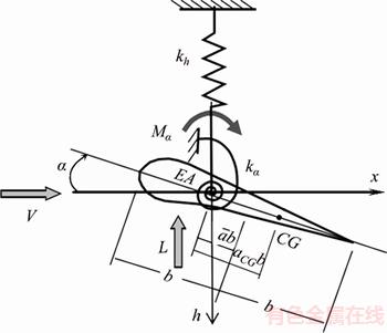
Figure 1 2D blade section
Based on Lagrange’s equation,
 (6)
(6)
where T is the kinetic energy of the system and U is the potential energy, qj are the generalized coordinates and Qj are the generalized forces, in which q1=h, q2=α, Q1=–L, Q2=Mα.
Combining Eq. (4), Eq. (5) and Eq. (6), equation of motion for classical flutter is obtained. The motion equation is as follows:

 (7)
(7)
where and
and are the natural frequencies of the flapwise and torsional modes.
3 Solution methodology
As Theodorsen model is used to describe a airfoil simultaneously pitching and plunging in a oscillatory form as shown in Eqs. (8), equations of motion (i.e. Eqs. (7)) can be converted as Eqs. (9).


 (8)
(8)
where ω(ω=2πfosc) is the airfoil frequency of oscillation,  and
and  are the motion amplitudes, and
  and
and  are the amplitude of lift and pitching moment respectively.

 (9)
(9)
 (10)
(10)

 (11)
(11)
in which the following parameters for oscillating aerodynamic forces are used:
 (12)
(12)
The above mentioned equations are related to fosc that is unknown. Therefore, an iterative procedure termed “V–g method” [21] is employed to determine fosc and the flutter speed VF. The equations of oscillatory motion required for use of the V–g method are described:
 (13)
(13)
where the dimensionless parameters Ω=ω/ωα and Rω=ωh/ωα are used, g is the artificial structural damping parameter, M is generalized mass matrix, K is generalized stiffness matrix, and A is matrix of generalized unsteady aerodynamic forces. The matrixes M, K and A are shown in Eq. (14).


 (14)
(14)
By simply transforming Eq. (13), the issue of classical flutter speed determination becomes an eigenvalue problem:
 (15)
(15)
The eigenvalue is:
 (16)
(16)
where λRe is the real part of complex number, and λIm is the imaginary part.
Finally, fosc, g and V are obtained:


 (17)
(17)
In order to figure out the V–g and V–fosc, the eigenvalue of the matrix (A+M)K–1 is calculated in a given range of the reduced frequency k. It is important to note that the real structural damping parameter of blade is difficult to determine, so the structural damping parameter g in the V–g method is usually assumed to be zero to give conservative results. The flutter speed VF takes the value of V when the structural damping parameter g is zero. Similarly, the airfoil frequency of oscillation fosc can be determined. Blade is stable when the inflow speed V is below the flutter speed VF, but unstable when the V exceeds the flutter speed VF.
Equation (7) can be solved in time domain since the airfoil frequency of oscillation fosc is obtained. By transforming Eq. (1) and Eq. (2), a new form of Theodorsen unsteady aerodynamics model is as follows:

 (18)
(18)
 (19)
(19)
 (20)
(20)
where


 and
and are dimentionless parameters for oscillating aerodynamic forces.
Combining Eq. (7) and Eq. (18), a new form of motion equations for classical flutter is as follows:

 (21)
(21)
Runge-Kutta method is employed to solve the partial differential equations. The numerical solution is realized by employing ode45 function provided by the commercial software MATLAB. It is necessary to reduce the motion equations to a lower order when ode45 function is used. A simple reduced-order method for motion equations is shown in Eqs. (22) and (23).
To set
 (22)
(22)
then we get
 (23)
(23)
4 Results and analysis
A case study of blade flutter on the virtual 5 MW pitch-regulated turbine with three blades designed by NREL [22] is performed. The turbine has a 126-m-diameter rotor with 61.5-m-long blades. The blade was composed of 18 tipical sections. The chord length and twist angle distribution along span-wise of the blade are shown in Figures 2 and 3. The distributed blade structural properties of the NREL 5 MW blade are based on the structural properties of the 62.6-m-long LM Glasfiber blade used in the DOWEC (Dutch Offshore Wind Energy Converter project) study (cf. Appendix A of Ref. [23]). The blade design is close to an actual blade with the same approximate distributions of bending and torsional stiffness, center of gravity, and mass per unit-length along the blade span.
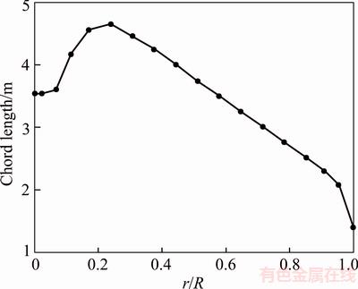
Figure 2 Chord length distribution along span-wise of blade

Figure 3 Twist angle distribution along span-wise of blade
Because blade stiffness is lower and distance of the section to the root is larger near the blade tip, the closer the blade tip to the section is, the more representative it is. However, Theodorsen unsteady aerodynamics model may not be appropriate for the aerodynamic forces calculation due to the existence of blade tip vortex when the blade tip is selected as the representative section. In this paper, the 60 m station at the blade is selected as the representative section. The structural properties at the representative section are determined by interpolating between the 59.7 m and 60.2 m stations given in Appendix A of Ref. [22]. The properties of the representative section are listed in Table 1.
The nominal rotor speed is 12.1 r/min (revolutions per minute), and the rated wind speed is 11.4 m/s. The inflow speed is about 78.7 m/s under rated condition. It is interesting to investigate how far this operational speed of the turbine is from the flutter speed. As shown in Figure 4, the flutter speed is 103 m/s, so the NREL 5-MW baseline turbine will not flutter under rated condition. The airfoil frequency of oscillation fosc is 5.68 Hz corresponding to the flutter speed as illustrated in Figure 5. Figure 6 shows the time domain aeroelastic response of the representative section under three different inflow speed conditions (i.e., 100, 103 and 106 m/s). The section is stable when the inflow speed is 100 m/s, whereas it goes unstable when the inflow speed increases to 106 m/s, and persistent oscillation at 103 m/s. The time domain aeroelastic response further validates the accuracy of the results obtained by introducing “V–g” method to the aeroelastic model.
Table 1 Properties of representative section

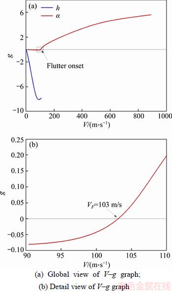
Figure 4 V–g graph:
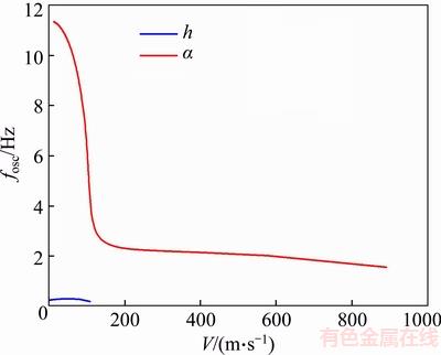
Figure 5 V–fosc graph

Figure 6 Time domain aeroelastic response of representative section:
The sensitivity of the flutter speed to the frequency ratio Rω is presented in Figure 7. Since the torsional stiffness kα and the flapwise stiffness kh is proportional to the torsional frequency ωα and the flapwise frequency ωh respectively, the torsional and flapwise stiffness are selected as parameters instead of the frequencies to study how they affect the flutter speed. The blue line in Figure 7 corresponds to the fixed torsional stiffness kα and the red one represents the fixed flapwise stiffness kh. For the first case, the flutter speed VF keeps constant with the variation of the flapwise stiffness when the torsional stiffness is fixed, which indicates that the flapwise stiffness has less effect on the flutter speed. In another case, the flutter speed VF increases gradually with the increase of the torsional stiffness when the flapwise stiffness is fixed, indicating that the torsional stiffness has a great effect on the flutter speed. Accordingly, the stability of wind turbine blade can be improved by increasing the torsional stiffness of the blade.
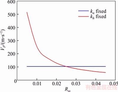
Figure 7 Relationship between frequency ratio Rω and flutter speed VF
The dimensionless parameters aCG and  are used to represent the chordwise position of the center of gravity and the elastic axis respectively. As shown in Figures 8 and 9, the flutter speed is closely related to aCG and . The flutter speed decreases as the center of gravity is moved towards the trailing edge of section, which explains the issue why the mass added to leading edges of aircraft wings is a practical solution to flutter problems. Similarly, the flutter speed also decreases when the elastic axis is close to trailing edge.

Figure 8 Relationship between chordwise position of center of gravity and flutter speed VF

Figure 9 Relationship between chordwise position of elastic axis and flutter speed VF
The relationship between the flutter speed and air density is shown in Figure 10, in which the flutter speed decreases with the increase of air density. Then it is concluded that the risk of flutter of wind turbine in high altitude is minor only considering the factor of air density.
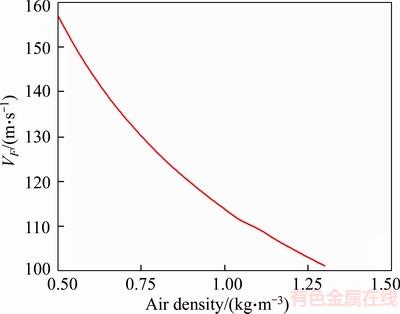
Figure 10 Relationship between air density and flutter speed VF
5 Conclusions
The parameter sensitivities affecting the flutter speed of the NREL 5-MW baseline horizontal axis wind turbine blades are analyzed. An aeroelastic model is established to describe the classical flutter of the blades by coupling Theodorsen unsteady aerodynamics model with Lagrange’s equation. The flutter speed is determined by introducing “V–g” method to the aeroelastic model, which converts the issue of classical flutter speed determination into an eigenvalue problem. Furthermore, the time domain aeroelastic response of the wind turbine blade section is obtained with employing Runge-Kutta method. Finally, the following conclusions can be drawn from the investigation.
1) The flapwise stiffness has less effect on the flutter speed, while the torsional stiffness has great effect on the flutter speed. The stability of wind turbine blade can be improved by increasing the torsional stiffness of the blade.
2) The flutter speed decreases as the center of gravity is moved towards the trailing edge of the section. Similarly, the flutter speed also decreases when the elastic axis is close to trailing edge. Adding mass to leading edges of blade is a feasible solution to the flutter problems.
3) The flutter speed decreases as air density increases, indicating that the risk of flutter in high altitude wind turbine is minor only considering the factor of air density.
4) The flapwise and torsional stiffness, center of gravity, elastic axis and air density should be comprehensively analyzed to avoid flutter in blade design.
References
[1] PEERINGA J, BROOD R, CEYHAN O, ENGELS W, de WINKEL G. Up wind 20MW wind turbine pre-design [R]. Petten: Energy Research Center of the Netherlands, 2011.
[2] HAU E. Wind turbines-fundamentals, technologies, application, economics [J]. IEEE Electrical Insulation Magazine, 2003, 19(2): 48.
[3] BIR G, JONKMAN J. Aeroelastic instabilities of large offshore and onshore wind turbines [C]// EAWE 2007 Torque. Lyngby: IOP, 2007: 1–19.
[4] HANSEN MOL, S RENSEN J N, VOUTSINAS S, SRENSEN N, MADSEN H A. State of the art in wind turbine aerodynamics and aeroelasticity [J]. Progress in Aerospace Sciences, 2006, 42(4): 285–330.
[5] LUNDSAGER P, PETERSEN H, FRANDSEN S. The dynamic behaviour of the stall-regulated Nibe A wind turbine. Measurements and a model for stall-induced vibrations [R]. Roskilde: Ris National Laboratory, 1981.
[6] STIESDAL H. Extreme wind loads on stall regulated wind turbines [C]// Proceedings of the 16th British Wind Energy Association Conference. Stirling: BWEA, 1994: 101–106.
[7] WANG L, LIU X, RENEVIER N, STABLES M, HALL G M. Nonlinear aeroelastic modelling for wind turbine blades based on blade element momentum theory and geometrically exact beam theory [J]. Energy, 2014, 76: 487–501.
[8] RAFIEE R, TAHANI M, MORADI M. Simulation of aeroelastic behavior in a composite wind turbine blade [J]. Journal of Wind Engineering and Industrial Aerodynamics, 2016, 151(1): 60–69.
[9] HAYAT K, LECEA A, MORIONES C D, HA S K. Flutter performance of bend–twist coupled large-scale wind turbine blades [J]. Journal of Sound and Vibration, 2016, 370(1): 149–162.
[10] LOBITZ D W. Aeroelastic stability predictions for a MW-sized blade [J]. Wind Energy, 2004, 7(3): 211–224.
[11] LOBITZ D W, VEERS P S. Aeroelastic behavior of twist-coupled HAWT blades [J]. AIAA Paper, 1998, 98(29): 75–83.
[12] BAXEVANOU C, CHAVIAROPOULOS P, VOUTSINAS S, VLACHOS N. Evaluation study of a Navier–Stokes CFD aeroelastic model of wind turbine airfoils in classical flutter [J]. Journal of Wind Engineering and Industrial Aerodynamics, 2008, 96(8): 1425–1443.
[13] HOOGEDOORN E, JACOBS G B, BEYENE A. Aero-elastic behavior of a flexible blade for wind turbine application: A 2D computational study [J]. Energy, 2010, 35(2): 778–785.
[14] DRELA M. An analysis and design system for low Reynolds number airfoil aerodynamics [C]// Low Reynolds Number Airfoil Aerodynamics. Indiana: Springer Berlin Heidelberg, 1989: 1–12.
[15] LI L, LI Y, LV H, LIU Q. Flapwise dynamic response of a wind turbine blade in super-harmonic resonance [J]. Journal of Sound and Vibration, 2012, 331(17): 4025–4044.
[16] MO W, LI D, WANG X, ZHONG C. Aeroelastic coupling analysis of the flexible blade of a wind turbine [J]. Energy, 2015, 89(1): 1001–1009.
[17] OWENS B C, GRIFFITH D, RESOR B R, HURTADO J E. Impact of modeling approach on flutter predictions for very large wind turbine blade designs [C]// Proceedings of the American Helicopter Society (AHS) 69th Annual Forum. Arizona: AHS, 2013: 21–23.
[18] HANSEN M H. Aeroelastic instability problems for wind turbines [J]. Wind Energy, 2007, 10(6): 551–577.
[19] THEODORSEN T. General theory of aerodynamic instability and the mechanism of flutter [R]. Washington, DC: National Advisory Committee for Aeronautics, 1949: 291–313.
[20] WRIGHT J R, COOPER J E. Introduction to aircraft aeroelasticity and loads [M]. Chichester: John Wiley & Sons, 2008.
[21] GWIN L, TAYLOR R. A general method for flutter optimization [J]. AIAA Journal, 1973, 11(12): 1613–1617.
[22] JONKMAN J M, BUTTERFIELD S, MUSIAL W, SCOTT G. Definition of a 5-MW reference wind turbine for offshore system development [R]. Colorado: National Renewable Energy Laboratory Golden, 2009.
[23] LINDENBURG C. Aeroelastic modelling of the LMH64-5 blade [R]. Petten: Energy Research Center of the Netherlands, 2002.
(Edited by HE Yun-bin)
中文导读
水平轴风力机叶片经典颤振速度参数敏感性分析
摘要:本文以NREL 5MW风力机为对象研究了影响风力机叶片经典颤振速度的关键参数。首先,建立了描述叶片颤振的气弹模型,该模型由叶片气动模型和结构动力模型耦合而成,其中气动部分为Theodorsen非定常气动力模型,结构部分根据拉格朗日方程得到。然后,采用“V–g”方法实现了气弹模型的数学求解,将带有复数的方程组求解转化为特征值求解问题。最后,采用龙哥库塔法求解得到了叶片在时域内的气弹响应。结果表明,降低叶片扭转刚度、将叶片截面质心或弹性轴位置向叶片前缘移动、或将风力机置于高空气密度区域将会降低叶片的颤振临界速度,即叶片更容易发生颤振。因此,综合考虑叶片扭转刚度、截面质心或弹性轴位置以及空气密度对提高叶片颤振临界速度至关重要。
关键词:风力机叶片;气弹模型;经典颤振;参数敏感性分析
Foundation item: Project(2015B37714) supported by the Fundamental Research Funds for the Central Universities of China; Project(51605005) supported by the National Natural Science Foundation of China; Project(ZK16-03-03) supported by the Open Foundation of Jiangsu Wind Technology Center, China; Project([2013] 56) supported by the First Group of 2011 Plan of Jiangsu Province, China
Received date: 2017-01-14; Accepted date: 2017-04-05
Corresponding author: CAI Xin, PhD, Professor; Tel: +86–187–51955685; E-mail: xcai@hhu.edu.cn; ORCID: 0000-0001-9620-0135

