
J. Cent. South Univ. (2019) 26: 229-240
DOI: https://doi.org/10.1007/s11771-019-3996-8

Parameter optimization for improved aerodynamic performance of louver-type wind barrier for train-bridge system
HE Xu-hui(何旭辉)1, 2, 3, FANG Dong-xu(方东旭)4, LI Huan(李欢)1, 2, SHI Kang(史康)1, 2
1. School of Civil Engineering, Central South University, Changsha 410075, China;
2. National Engineering Laboratory for High Speed Railway Construction, Changsha 410075, China;
3. Joint International Research Laboratory of Key Technology for Rail Traffic Safety,Changsha 410075, China;
4. China State Construction International Investments (China) Limited, Shenzhen 518000, China
 Central South University Press and Springer-Verlag GmbH Germany, part of Springer Nature 2019
Abstract: To improve the safety of trains running in an undesirable wind environment, a novel louver-type wind barrier is proposed and further studied in this research using a scaled wind tunnel simulation with 1:40 scale models. Based on the aerodynamic performance of the train-bridge system, the parameters of the louver-type wind barrier are optimized. Compared to the case without a wind barrier, it is apparent that the wind barrier improves the running safety of trains, since the maximum reduction of the moment coefficient of the train reaches 58% using the louver-type wind barrier, larger than that achieved with conventional wind barriers (fence-type and grid-type). A louver-type wind barrier has more blade layers, and the rotation angle of the adjustable blade of the louver-type wind barrier is 90–180° (which induces the flow towards the deck surface), which is more favorable for the aerodynamic performance of the train. Comparing the 60°, 90° and 120° wind fairings of the louver-type wind barrier blade, the blunt fairing is disadvantageous to the operational safety of the train.
Key words: wind barrier; aerodynamic force; train-bridge system; scaled wind tunnel simulation; parameter optimization
Cite this article as: HE Xu-hui, FANG Dong-xu, LI Huan, SHI Kang. Parameter optimization for improved aerodynamic performance of louver-type wind barrier for train-bridge system [J]. Journal of Central South University, 2019, 26(1): 229–240. DOI: https://doi.org/10.1007/s11771-019-3996-8.
1 Introduction
Strong winds often lead to train derailment or overturning, and their mechanism of action and methods of control are problems that remain to be solved. Despite improvements to the high-speed railway network, a high-speed public transportation train cannot completely avoid exposure to a typhoon, a mountain canyon wind or other strong winds in time and space [1–3]. Railway bridges account for a high proportion of the total line mileage; for example, the average proportion of China’s high-speed rail that is composed of bridges is 58.5%, of which the Beijing-Shanghai high-speed rail reached 80.5%, and the Guangzhou-Zhuhai intercity railway reached 94.2% [4]. Dynamic interactions between the train and the bridge as well as aerodynamic interference further exacerbate the safety risks for a train operating in an environment with strong winds. Several measures have been applied to improving the operational safety of a high-speed train in strong winds [5–7]. A wind barrier is one of the most commonly used techniques, providing a relatively low wind speed environment for the train [8–10]. Wind barriers are currently applied to Japan’s Shinkansen [11] and China’s Lanzhou-Xinjiang lines [12], but additional in-depth study is needed.
In recent years, scaled wind tunnel simulations and CFD simulations have been conducted on wind barriers. TAKEDA et al [13] compared the wind-tunnel test with field measurements, and measured the changes in mean wind speed and turbulence intensity around grid-type wind barriers with different forms and porosity factors. DONG et al [14, 15] used the PIV wind-tunnel test techniques to investigate the characteristics of the wind field in the rear area of a fence-type wind barrier with different porosity factors on the bottom wall of a wind tunnel. A CFD large eddy simulation model was used by CHU et al [16] to study the protective effect of grid-type wind barriers with different heights and porosity factors, the results showed that the wind barrier could evidently diminish the side force coefficient of the vehicle, and the wind barrier height of 2 m plus the block height of 0.8 m is enough to protect 3.6 m height vehicle. A wind tunnel test of the 1:50 scale vehicle model was conducted to address its effects on the aerodynamic performance of the vehicle with grid-type wind barriers of various geometry (height and solid) by COLEMAN et al [17]. The experimental results indicated that the risk of using the grid-type wind barriers is sharply reduced due to the drastic reduction of aerodynamic force on vehicles and the force coefficients at the vehicle corners have a strong Reynolds number effect, resulting in no obvious reduction. OGUETA- GUTI RREZ et al [18] conducted a wind-tunnel test to study the effect of both curved and linear wind barriers on the static aerodynamic coefficient and the vibration of a bridge. Most of the previously mentioned studies have focused on conventional (fence-type and grid-type) wind barriers. The geometric shape and the porosity of the barrier cannot be changed once it has been constructed. Consequently, it is difficult for current wind barriers to adapt to complex wind environments, such as a gust over complex terrain. In this research, a series of wind tunnel tests were performed using a novel louver-type wind barrier [19] that can adjust its shape and porosity. Based on the aerodynamic performance of the train-bridge system, the parameters of the louver-type wind barrier were optimized, including the number of blade layers and the wind fairing angle of blade.
2 Scaled wind tunnel simulation
The experiments were conducted in the wind tunnel with closed-circuit atmospheric boundary layer of the National Engineering Laboratory for High Speed Railway Construction at Central South University. The dimensions of the test section were 3 m (width)×3 m (height)×15 m (length). The continuously adjustable wind speed ranged from 0 to 94 m/s, and turbulence intensity was less than 0.5%. A schematic of the experimental setup is presented in Figure 1. The measured oncoming flow velocity was U∞=10 m/s. The scale ratio was chosen to be 1:40 for all test models, including the bridge, train and wind barriers. The length of the bridge model was 2 m. The lift, drag and moment coefficients for both the train and the bridge were obtained using a 6-component force balance (Nitta JR3), with the oncoming flow velocity measured using a cobra probe (TFI Series 100). The geometric similarity of the test models was strictly satisfied, and the strength and stiffness of the structure was fully achieved. While the blockage ratio of this model system was calculated to be 4.2% (less than the 5% requirement), its effects can be ignored in the test results [20]. The thickness of the boundary layer in this test segment was approximately 200 mm, indicating that the model is in a state of uniform flow [21].
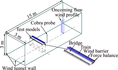
Figure 1 Schematic diagram of experimental setup
2.1 Wind barriers
A louver-type wind barrier uses rotating blades for discharge and diversion to ensure the operational safety of trains or vehicles in a strong wind environment based on the principles of the shading and ventilation properties of louvers. The working principle of the louver-type wind barrier with three-layer blades is illustrated in Figure 2. The blades of the wind barrier can rotate in the range of 0–180°; 0° is the initial state, in which the porosity factor of the wind barrier is 0. When the rotation angle is 90°, the porosity factor reaches a maximum. The porosity factors of the barriers in different layers are not the same, due to blade thickness. When the rotation angle is 180°, the blades once again return to the initial state.
As shown in Figure 3(a), the total height of the wind barrier model is 75 mm, the thickness is 5 mm, and the total length is 2000 mm. Louver-type wind barriers with one, two and three layers of blades were studied in this experiment. The wind barriers on either side of the bridge are assumed to rotate in a symmetrical fashion, and the rotation direction and angle are consistent for each blade on the same side. In contrast with the fence-type wind barrier, the louver-type wind barrier is made up of two layers of blades. The blade rotation angles of 30°, 45° and 60° correspond to the fence-type wind barriers of different heights and gaps respectively, and the porosity are respectively 12%, 26%, and 42%, which are consistent with the porosity, size, etc. of the grid-type wind barrier in the literature [19]. The angle of rotation and fixing mode of the louver-type wind barrier model are shown in Figure 4. The angle of the blades is precisely maintained through the column with positioning holes and dials, and the blades are fixed using a screw, nut and lock.
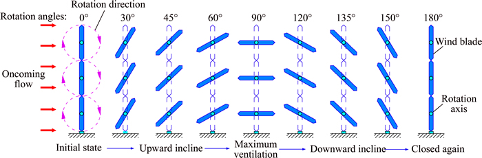
Figure 2 Working principles of a louver-type wind barrier with three-layer blades
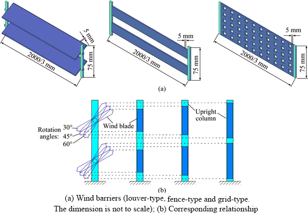
Figure 3 Model dimensions and porosity relationships for a louver-type and a fence-type:

Figure 4 Rotation angle and fixing method of louver- type wind barrier
2.2 Bridge and train
The train-bridge system in this research is based on a specific rail-transit bridge located in Chongqing, China. The bridge is a cable-stayed bridge with twin-towers and a double-cable planes hybrid beam, the main span of which is 340 m. It is the largest span cable-stayed bridge in China’s specific rail-transit bridge, across the Jialing River in southwest China (Figure 5(a)). The cross- sectional dimensions of the bridge and train test scale models, in which the aerodynamic shapes were carefully considered, are shown in Figures 5(b) and (c). The train and bridge models were made of PVC board and high-quality timber, respectively, with steel core beam skeletons to ensure sufficient strength and stiffness.
2.3 Measurement system
The aerodynamic forces on the train and the bridge were measured by an aerodynamic synchronous separation measurement system on the custom-made train-bridge combined segment model. As shown in Figure 6, the rotation principle of the device is similar to that of the louver angle rotation device. There are two dials with a specific gap between them which facilitates the adjustment of the wind attack angle in the aerodynamic force separation test. The train model is affixed to the outside fixed dial by the slider. The bridge model is affixed to the inside rotatable dial. The four 6-component force balances are connected to the two ends of the train model and the bridge model. The dial has a total of 120 location holes at different positions which are rotated and fixed to achieve the minimum rotation angle of 1°. The precision of each 6-component force balance is 0.02 N, the sampling frequency is 1 kHz, and the sampling duration is 30 s. The sampling precision of the cobra probe is 0.5 m/s, its sampling frequency is 2 kHz and its sampling duration is 20 s.
2.4 Parameter definition
Figure 7 shows the parameters defined in this test. For the louver-type wind barrier, the total height Hw=75 mm, the total length L=2 m, the individual blade height h=Hw/n (n for blade layers), the blade rotation angle is α, the angle of the blade wind fairing is θ, and without considering the blade thickness, its porosity factor is calculated as:

Figure 5 Geometric dimension:(Unit: mm)

Figure 6 Schematic diagram of train-bridge synchronous separation measurement system
 (1)
(1)
Bi and Hi (with i=t or b, representing the bridge or the train) are the sectional width and height of the train and the bridge, and F i H, F i V and M i T (i=t or b) represent the drag, lift and moment forces of the train or the bridge, respectively. During the test, the aerodynamic force on the centroid of the train and the bridge is measured by the balance. To better reflect the influence of wind load on train operational safety, the torsion center of the train moment is transferred from the centroid to the center of the rail on the leeward side. The conversion relationship between M t T0 and M T is (refer to Figure 7):
 (2)
(2)
where x and y are the horizontal and vertical distances from the centroid of the train model to the center of the leeward side rail (x=17.94 mm, y=51.68 mm). The aerodynamic coefficients of the train and the bridge in the body-axis coordinate system are [22]:
 (3)
(3)
 (4)
(4)
 (5)
(5)
where C i D, C i L and C i M (i=t or b) represent the drag, lift and moment coefficients of the train or the bridge, respectively, ρ is the air density (ρ=1.225 kg/m3), and U is the model reference point wind speed measured by the cobra probe. In general, the train is prone to overturning in strong winds, so M T pertains most closely to the safety of train operation.
3 Results and discussion
HE et al [19] proved that the aerodynamic synchronous separation measurement system has sufficient reliability in an aerodynamic measurement test of a train and a bridge. In this experiment, the aerodynamic forces on the train- bridge system with the different types and parameters of wind barriers is measured by the measurement system, which was located on the windward side of the tested train.
3.1 Comparison with conventional wind barriers
Conventional wind barrier types include grid-type and fence-type barriers. The test setup is shown in Figure 8. In this research, the impact of the louver-type wind barrier with two layers of 90° blades, a wind fairing at 30°, 45° and 60° rotation angles and a fence-type wind barrier with the same porosity factors (12%, 26% and 42%. It is based on Eq. (1), considering the influence of blade thickness and the blocking effect of the upright column) on the aerodynamic forces of the train-bridge system were studied. The porosity factors and size of the grid-type wind barrier studied are consistent with those in Ref. [19]. The specific conditions are listed in Table 1.

Figure 7 Schematic diagram of defined parameters
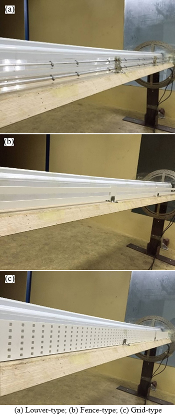
Figure 8 Three types of wind barriers in wind tunnel:
Figure 9 shows the comparison of the results for the louver-type wind barrier and the fence-type wind barrier, along with the results for the grid-type wind barrier [19] and no wind barrier. In Figure 9(e), C t Lwith fence-type wind barrier is much greater than those with the other two types, the possible reason is that the fence-type wind barrier resembles the two side-by-side flat plates, forming ‘slot jet’ through a strip of gap. The slot jet causes a complex vortex shedding in the wake, while the train in such wakes significantly increases the lateral instability, so the C t L is much greater [23, 24]. Compared with conventional wind barriers, the louver-type wind barrier significantly reduces C b D and C b M, and increases C b L somewhat. In addition, the louver-type wind barrier increases C t D relatively, and reduces C t L and C t M. Since the torsion center of C t M has been converted to the rail of the train leeward side, it better reflects train safety considerations. Compared with the case without a wind barrier, C t M for the grid-type wind barrier is reduced by at most 45.2%, for the fence-type wind barrier C t Mis reduced by 53.6%, and for the louver-type wind barrier, C t M is reduced by 58.0%. Considering the safety of train operation in the porosity range of the test, the louver-type barrier performs better than the fence-type, and the fence-type performs better than the grid-type. In general, using wind barriers will reduce the main wind load on the train-bridge system.
3.2 Blade layer optimization
As shown in Figure 10, the experiments were carried out on louver-type wind barriers with one, two and three layers of blades with the same height Hw, with blade wind fairing angles of 90°. The test conditions are shown in Table 2.
The changes in aerodynamic coefficients for the bridge and the train are shown in Figure 11. The influence of the louver-type wind barriers with different blade configurations on the aerodynamic coefficients of the bridge and train is about the same, especially for C b M and C t M. In general, as the number of layers increases, C b L (the negative sign indicates direction) and C b M increase, and C b D decreases in the range of the number of blade layers studied. C t D and C t M decrease with the increase in the number of blade layers, while C t L increases. Therefore, according to the test results, more blade layers are beneficial from the point of view of train operational safety, but from a bridge-train system stability perspective, the aerodynamic coefficients of the train and the bridge must be considered. Specially, in the case α=0° (solid barrier), the coefficients of the train is very low, even negative values, which is consistent with the literature [25]. But at this time C b D is high enough. In addition, the wind barrier reduces C t M by at least 28.0% (when a layer of blades rotates 90°), and significantly improves the safety of train operation. With the increase of rotation angle, C b D first decreases and then increases, C b L and C b M first increase and then decrease, and C t D and C t L first increase and then decrease. The extreme values occur near the blade rotation angles of 60–90°, where C t L first decreases, then increases and then decreases. The variation is similar in shape to the cosine function. It is worth noting that the porosity factor is not 100% when the blade thickness is nonzero and the blade is rotated 90°, and the corresponding porosity factors are 93%, 87% and 80% for one, two and three layers of blades rotated 90°, respectively. Due to the symmetry of the rotation of the blades, the porosity factor is symmetrical about the 90° rotation angle. However, the aerodynamic coefficients of the bridge and the train are not symmetrical, because the change in the blade’s inclination direction leads to a change in the bleed flow, and reversed flow behind the wind barrier causes asymmetry of the aerodynamic coefficients of the bridge or the train. For operational safety of the train-bridge system, it is suggested that the blade rotation of the louver-type wind barrier is in the range of 90–180°, which is connected to the aerodynamic shape of the train and the bridge.
Table 1 Comparison between fence-type wind barrier and louver-type wind barrier


Figure 9 Comparison of aerodynamic coefficients for bridge and train for louver-type, fence-type and grid-type [19] wind barriers (The data includes the case of no wind barrier):

Figure 10 Three configurations of wind blades in wind tunnel experiment:
Table 2 Three configurations of blade layers
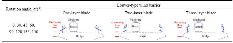
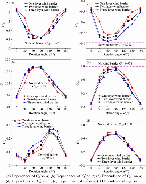
Figure 11 Aerodynamic coefficients of bridge and train in three configurations of blade layers:
3.3 Blade wind fairing optimization
To improve the aerodynamic performance of long span bridges, a wind fairing is often affixed to both sides of a bridge section, and a certain fairing angle is selected so that the airflow separates smoothly on the windward face of the bridge [26, 27]. The two ends of the blade are also provided with a similar fairing so that the incoming flow may be smoothly separated at the blade tip. In this experiment, fairing angles of 60°, 90° and 120° are selected to study the effect of blade angle on the train-bridge aerodynamic forces. The test wind barrier is a louver-type wind barrier with two layers of blades and the same height. The specific test conditions are shown in Table 3.
Table 3 Various types of wind fairings
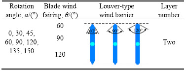
Figure 12 shows the aerodynamic coefficients for bridges and trains when louver-type wind barriers with 60°, 90° or 120° wind fairing are in place. The angle of the blade wind fairing has little effect on the train-bridge aerodynamic force, but the results clearly indicate that C b D, C b L and C b M are minimized when the fairing angle is 60°, resulting in a more aerodynamically stable bridge. C t L and C t M are at a minimum, and C t D is at an intermediate value, indicating a 60° nozzle angle is also more conducive to aerodynamic safety of the train. When the nozzle angle is 90°, all the aerodynamic coefficients except Cb D are at a maximum (absolute value). Consequently, a blunt blade fairing is not conducive to train-bridge aerodynamic safety. In general, the best fairing angle of the blade is 60°, and the most disadvantageous angle is 90°. Therefore, a blunt wind fairing should be avoided when selecting the fairing angle of blade.
4 Conclusions
The aerodynamic characteristics of both the train and the bridge with the novel louver-type wind barrier subjected to a crosswind were investigated using wind tunnel tests. The parameters pertaining to this novel wind barrier were also optimized. The following conclusions can be drawn from this study:
1) The running safety of a train in an undesirable wind environment is improved by utilizing a wind barrier, which reduces most aerodynamic coefficients for the train and the bridge. Compared with the case without a wind barrier, the maximum decreases of CM for the train are 45.2%, 53.6% and 58.0% for grid-type, fence- type and louver-type wind barriers, respectively.

Figure 12 Aerodynamic coefficients for bridge and train with various types of wind fairings:
2) A louver-type wind barrier is more favorable than fence-type and grid-type barriers for the aerodynamic performance of a train. It can significantly reduce the CD and CM of the bridge, and CL and CM of the train.
3) With variation in the number of blade layers in the louver-type barrier, no obvious difference in the aerodynamic coefficients of the bridge and the train is apparent. However, it is better to choose a louver-type wind barrier with more layers, considering the CM of the train.
4) Most of the extreme values of aerodynamic coefficients occur with louver-type barrier blade rotation angles of 60–90°. Moreover, the CM of the train is generally smaller when the inclined angle is between 90° and 180°.
5) The wind fairing angle of blade has little effect on the aerodynamic coefficients of the train and the bridge. Comparing three kinds of fairing angles of the blade, the optimal angle is 60°, while the worst is 90°. Therefore, it is necessary to avoid selecting a blade with a blunt fairing during engineering design.
References
[1] BETTLE J, HOLLOWAY A G L, VENART J E S. A computational study of the aerodynamic forces acting on a tractor-trailer vehicle on a bridge in cross-wind [J]. Journal of Wind Engineering and Industrial Aerodynamics, 2003, 91(5): 573–592.
[2] ZHANG Ming-jin, LI Yong-le, WANG Bin. Effects of fundamental factors on coupled vibration of wind-rail vehicle-bridge system for long-span cable-stayed bridge [J]. Journal of Central South University, 2016, 23(5): 1264– 1272.
[3] SUZUKI M, TANEMOTO K, MAEDA T. Aerodynamic characteristics of train/vehicles under cross winds [J]. Journal of Wind Engineering and Industrial Aerodynamics, 2003, 91(1): 209–218.
[4] HE Xu-hui, WU Teng, ZOU Yun-feng, CHEN Y F, GUO Hui, YU Zhi-wu. Recent developments of high-speed railway bridges in china [J]. Structure and Infrastructure Engineering, 2017, 13(12): 1584–1595.
[5] MATSCHKE G, SCHULTE-WERNING B. Measures and strategies to minimise the effect of strong cross winds on high speed trains [C]// Proceedings of World Congress of Railway Research (Bautechnik). Berlin: Ernst & Sohn Verlag für Architektur und technische Wissenschaften, 1997: 569– 575.
[6] IMAI T, FUJII T, TANEMOTO K, SHIMAMURA T, MAEDA, ISHIDA H, HIBINO Y. New train regulation method based on wind direction and velocity of natural wind against strong winds [J]. Journal of Wind Engineering and Industrial Aerodynamics, 2002, 90(12): 1601–1610.
[7] RAGHUNATHAN RS, KIM H D, SETOGUCHI T. Aerodynamics of high-speed railway train [J]. Progress in Aerospace Sciences, 2002, 38(6): 469–514.
[8] HE Xu-hui, ZOU Yun-feng, WANG Han-feng, HAN Yan, SHI Kang. Aerodynamic characteristics of a trailing rail vehicles on viaduct based on still wind tunnel experiments [J]. Journal of Wind Engineering and Industrial Aerodynamics, 2014, 135: 22–33.
[9] HE Xu-hui, ZHOU Lei, CHEN Zheng-wei, JING Hai-quan, ZOU Yun-feng, WU Teng. Effect of wind barriers on the flow field and aerodynamic forces of a train–bridge system [J]. Proceedings of the Institution of Mechanical Engineers Part F Journal of Rail and Rapid Transit, 2018, 0(0): 1–15.
[10] KOZMAR H, PROCINO L, BORSANI A, BARTOLI G. Optimizing height and porosity of roadway wind barriers for viaducts and bridges [J]. Engineering Structures, 2014, 81: 49–61.
[11] FUJII T, MAEDA T, ISHIDA H, IMAI T, TANEMOTO K, SUZUKI M. Wind-induced accidents of train/vehicles and their measures in Japan [J]. Quarterly Report of Rtri, 1999, 40(1): 50–55.
[12] GUO Wei-wei, XIA He, KAROUMI R, ZHANG Tian, LI Xiao-zhen. Aerodynamic effect of wind barriers and running safety of trains on high-speed railway bridges under cross winds [J]. Wind and Structures, An International Journal, 2015, 20(2): 213–236.
[13] TAKEDA K, YASUDA K, TAKEUCHI M, KANEDA Y. Wind tunnel test on the performance of windbreak and snow fences [J]. Journal of Wind Engineering, 1985, 25: 15–32.
[14] DONG Zhi-bao, LUO Wan-yin, QIAN Guang-qiang, WANG Hong-tao. A wind tunnel simulation of the mean velocity fields behind upright porous fences [J]. Agricultural and Forest Meteorology, 2007, 146(1, 2): 82–93.
[15] DONG Zhi-bao, LUO Wan-yin, QIAN Guang-qiang, LU Ping, WANG Hong-tao. A wind tunnel simulation of the turbulence fields behind upright porous wind fences [J]. Journal of Arid Environments, 2010, 74(2): 193–207.
[16] CHU C R, CHANG C Y, HUANG C J, WU T R, WANG C Y, LIU M Y. Windbreak protection for road vehicles against crosswind [J]. Journal of Wind Engineering and Industrial Aerodynamics, 2013, 116(5): 61–69.
[17] COLEMAN S A, BAKER C J. The reduction of accident risk for high sided road vehicles in cross winds [J]. Journal of Wind Engineering and Industrial Aerodynamics, 1992, 44(1–3): 2685–2695.
[18] OGUETA-GUTIRREZ M, FRANCHINI S, ALONSO G. Effects of bird protection barriers on the aerodynamic and aeroelastic behaviour of high speed train bridges [J]. Engineering Structures, 2014, 81: 22–34.
[19] HE Xu-hui, SHI Kang, WU Teng, ZOU Yun-feng, WANG Han-feng, QIN Hong-xi. Aerodynamic performance of a novel wind barrier for train-bridge system [J]. Wind and Structures, 2016, 23(3): 171–189.
[20] HOLMES J D. Wind Loading of Structures, Third Edition [M]. Boca Raton, FL: CRC Press, Taylor & Francis Group, 2015.
[21] WANG Han-feng, PENG Si, ZHOU Yu, HE Xu-hui. Transition along a finite-length cylinder in presence of a thin boundary layer [J]. Experiments in Fluids, 2016, 57(5): 1–10.
[22] BLEVINS R D. Applied fluid dynamics handbook [M]. Malabar, FL: Krieger Publishing Company, 1984.
[23] HAYASHI M, SAKURAI A, OHYA Y. Wake interference of a row of normal flat plates arranged side by side in a uniform flow [J]. Journal of Fluid Mechanics, 1986, 164: 1–25.
[24] AVILA-SANCHEZ S, LOPEZ-GARCIA O, CUERVA A, MESEGUER J. Characterisation of cross-flow above a railway bridge equipped with solid windbreaks [J]. Engineering Structures, 2016, 126: 133–146.
[25] BAKER C J. The wind tunnel determination of crosswind forces and moments on a high speed train [M]// TRANSAERO—A European Initiative on Transient Aerodynamics for Railway System Optimisation. Berlin Heidelberg: Springer, 2002: 46–60.
[26] HAO Zhan, PAN Xiao-min, NING Bo-wei. Self-adaptive fairing of steel box girder design and studies of flutter stability by CFD numerical simulation [C]// IABSE Congress Report. Zurich: International Association for Bridge and Structural Engineering, 2012: 1972–1979.
[27] HAQUE M N, KATSUCHI H, YAMADA H, NISHIO M. Investigation of edge fairing shaping effects on aerodynamic response of long-span bridge deck by unsteady RANS [J]. Archives of Civil and Mechanical Engineering, 2016, 16(4): 888–900.
(Edited by HE Yun-bin)
中文导读
基于车-桥系统气动性能分析的百叶窗型风屏障参数优化
摘要:为提高列车在复杂风环境中行车的安全性,本文采用1:40的缩尺模型进行风洞模拟试验,针对提出的一种新型百叶窗型风屏障对列车和桥梁的气动影响展开研究,并基于车-桥系统气动特性对百叶窗型风屏障的自身参数进行了优化分析。试验结果表明:设置风屏障可明显提高列车运行安全性,设置百叶窗型风屏障相对不设置风屏障列车扭矩系数减小58%;百叶窗型风屏障的防风效果优于传统风屏障(栅栏型和多孔型)的防风效果;百叶窗型风屏障的叶片层数较多、叶片角度旋转范围在90°~180°范围内(使气流导向桥面)时更利于列车安全运行;百叶窗叶片风嘴较钝时不利于车桥气动安全,其中叶片风嘴角度为60°时更优,90°时最不利。
关键词:风屏障;气动力;车-桥系统;风洞缩尺模拟;参数优化
Foundation item: Project(2017T001-G) supported by the Science and Technology Research and Development Program of China Railway Corporation; Project(2017YFB1201204) supported by the National Key Research and Development Program of China; Project(U1534206) supported by the National Natural Science Foundation of China; Project(2015CX006) supported by the Innovation-driven Plan in Central South University, China; Project(2017zzts521) supported by the Fundamental Research Funds for the Central Universities, China
Received date: 2018-04-09; Accepted date: 2018-10-22
Corresponding author: FANG Dong-xu, Master, Engineer; Tel: +86-15243629234; E-mail: fangdongxu@csu.edu.cn; ORCID: 0000- 0003-3875-9306

