Ͳ�μ���̬��������ѹ���������ɱ�����ʧ�ȷ���
��Դ�ڿ����й���ɫ����ѧ��(Ӣ�İ�)2016���8��
�������ߣ������� �Գ��� ������ ��ʢ��
����ҳ�룺2188 - 2196
�ؼ��ʣ���̬��������ѹ�����Σ����ʧ�ȣ�Ͳ�μ�
Key words��hot-granule medium-pressure forming; deep-drawing; instability; cylindrical part
ժ Ҫ��������̬����������ʳ��ι��նԽ������Ͳ�μ�����չ���о����õ���ı��ι����е�Ӧ���ֲ�����������ϰ������ʧ�����۸������ɱ�������ͷ�ٽ����ѳ���ѹ���Ľ�������ʽ���о�����������������������е�����Ħ��ЧӦ����ѹ�Ǿ��ȷֲ�������������߰�ĵij������ܣ���ͷ�ٽ����ѳ���ѹ��������������ļ�Ħ�������Ͳ�������Ӧ��ȵ����Ӷ������������Ӳ��ָ�������Ӷ��½��������ضԳ�ͷ�ٽ����ѳ���ѹ��Ӱ���ɴ�С��˳��Ϊ����Ӧ��ȡ�Ħ��������Ӳ��ָ���������AZ31Bþ�Ͻ���HGMF���������ʧ�����۽�����֤��
Abstract: The cylindrical part of sheet metal based on hot-granule medium-pressure forming (HGMF) technology was investigated. The stress functions of the free deformation zone and the fracture instability theory were combined to establish the analytical expression of the critical pressure of punch. The results show that the active friction between the granule medium and the sheet metal, as well as the non-uniform internal pressure presented by the solid granule medium, can obviously improve the forming performance of the sheet metal. The critical pressure of punch increases with the increment of the friction coefficient between the granule medium and sheet metal, as well as the plastic strain ratio, whereas it decreases with the increase of the material-hardening exponent. Furthermore, the impact on the critical pressure from high to low order is the plastic strain ratio, the friction coefficient, and material-hardening exponent. The deep-drawing experiment with HGMF technology on AZ31B magnesium alloy sheet verified the instability theory.
Trans. Nonferrous Met. Soc. China 26(2016) 2188-2196
Miao-yan CAO1, Chang-cai ZHAO2, Guo-jiang DONG3, Sheng-fu YANG1
1. College of Mechanical Engineering, Yanshan University, Qinhuangdao 066004, China;
2. Key Laboratory of Advanced Forging & Stamping Technology and Science, Ministry of Education, Yanshan University, Qinhuangdao 066004, China;
3. College of Vehicles and Energy, Yanshan University, Qinhuangdao 066004, China
Received 10 August 2015; accepted 3 December 2015
Abstract: The cylindrical part of sheet metal based on hot-granule medium-pressure forming (HGMF) technology was investigated. The stress functions of the free deformation zone and the fracture instability theory were combined to establish the analytical expression of the critical pressure of punch. The results show that the active friction between the granule medium and the sheet metal, as well as the non-uniform internal pressure presented by the solid granule medium, can obviously improve the forming performance of the sheet metal. The critical pressure of punch increases with the increment of the friction coefficient between the granule medium and sheet metal, as well as the plastic strain ratio, whereas it decreases with the increase of the material-hardening exponent. Furthermore, the impact on the critical pressure from high to low order is the plastic strain ratio, the friction coefficient, and material-hardening exponent. The deep-drawing experiment with HGMF technology on AZ31B magnesium alloy sheet verified the instability theory.
Key words: hot-granule medium-pressure forming; deep-drawing; instability; cylindrical part
1 Introduction
Structural components with lightweight sheets, such as magnesium and aluminum alloys, are widely applied in the automobile, aerospace, and other industrial fields because of the urgent need for low energy consumption and low emission [1]. Traditional forming method by drawing involves serious difficulties, such as high cost, low efficiency, time consuming and human resources used during the die designing, manufacturing and trouble solving because of the poor formability of lightweight alloy sheets at room temperature.
In recent years, warm/hot flexible-die forming technologies, such as warm hydroforming [2-6], super plastic forming process [7], quick plastic forming process [8], and viscous medium forming [9,10], exhibited considerable breakthroughs. In these technologies, fractures and wrinkles are the main issues involved in the sheet-forming task. In Refs. [11,12], the method of combining theoretical analysis with a test was adopted to obtain the critical blank-holder force for the deep-drawing of cylindrical parts. In Ref. [13], the fracture instability for deep-drawing by hydroforming was studied.
The theoretical results and engineering experiences in warm/hot flexible-die forming are extensive, and these technologies have been excellent options for the manufacture of components with lightweight materials. However, current theoretical studies are only based on liquid/gas forming technology with uniform distribution of internal pressure and non-friction.
Hot-granule medium-pressure forming (HGMF) is a technology in which the rigid punch/die (or elastomer, liquid, gas) is replaced by heat-resistant solid granules to conduct warm/hot flexible-die forming on sheet metals, as shown in Fig. 1. This technology overcomes the problem of sealing in warm/hot forming and excessive thinning during forming because of the active friction and non-uniform distribution of internal pressure. Producing certain parts with complex cross-sections using this technology is possible. A number of local and international researchers have conducted detailed studies on this technology [14-20].
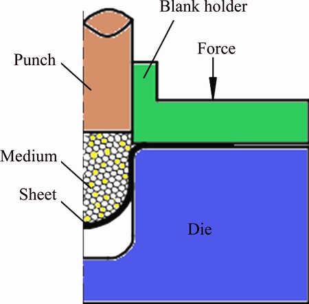
Fig. 1 Schematic of PGMF technology
Theoretical researches on HGMF technology with friction and non-uniform distribution of internal pressure are not mentioned in existing studies. Therefore, in the present study, the instability of free deformation zone of cylindrical parts was investigated based on the HGMF technology. The influences of process parameters on critical pressure of punch, such as friction coefficient between granule medium and sheet metal, comparison between plastic-strain ratio and material-hardening exponent, and the feasibility of AZ31B magnesium alloy sheet using HGMF technology were explored.
2 Basic assumptions
Based on the characteristics of HGMF technology, the following hypotheses are proposed: the sheet is in the plane-stress state with the normal stress ignored; the thickness of the sheet metal is considered to be constant during the drawing process; the shear stress generated by friction is very small, and thus the direction of the deformation principal axis of the sheet metal does not change; and the stress�Cstrain relationship of the sheet metal conforms to the Holloman constitutive equation [21,22] as follows:
 (1)
(1)
where  is the equivalent stress, K is the strength coefficient, n is the material hardening exponent, and
  is the equivalent strain.
The transfer pressure (ph) by solid granule medium regularly attenuates with the pressure-transfer distance, and the attenuation law is expressed as follows [14]:
 (2)
(2)
where  ; N=p1 and ��w is the friction coefficient between granule medium and sheet metal; a and b are the constants of lateral pressure coefficient, which are measured by a test; h is the pressure-transfer distance of the granule medium; rb is the radius of the granular charging barrel system; p1 is the pressure of punch; and ph is the transfer pressure at the distance of h.
The sheet metal during the HGMF process is in a free drawing-bulging state before it adheres to the bottom of the die. The free deformation zone can be approximately regarded as a spherical cap and its meridian plane can be denoted by a circle function.
Fracture instability mostly occurs in the free deep-drawing zone according to the HGMF test, as shown in Fig. 2. When the sheet metal adheres to the cylinder wall of the die, the free-forming process can be divided into two stages, namely, the forming stages of die fillet and straight wall.
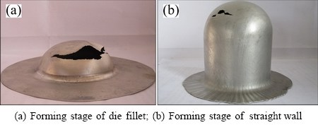
Fig. 2 Cylindrical parts with fracture instability (material: AZ31B)
3 Stress distribution in free deformation zone
The stress analysis was conducted in the free deformation zone based on PGMF technology with the forming stages of die fillet and straight wall.
3.1 Forming stage of die fillet
The forming stage of the die fillet on the part is presented in Fig. 3. The sheet metal is gradually drawn into the die fillet under the internal pressure of granule medium, and the wrap angle �� of the sheet metal to the die fillet satisfies the relationship 0��<��<90��. In this forming stage, the forming height H of the part satisfies the relationship 0
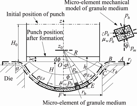
Fig. 3 Mechanical analysis of free deformation zone (0<��<90��)
In Fig. 3, t is the thickness of the sheet metal; R is the radius of free deformation zone; z0 is the center of fitting circle of the free deformation zone; ��E�� is the stress in the meridional direction of any point E in the free deformation zone; �� is the angle between the normal line of any point in the free deformation zone and the perpendicular axis; f is the angle between shear conical surface and perpendicular axis; H is the forming height of the part; H0 is the initial height of granule medium; X is the distance between the bottom of the punch and the surface of the flange; �� is the angle in which the sheet metal covers the die fillet; rd is the radius of the die fillet; rb is the radius of the die cylinder; rj is the radius at any point of the part; rE is the radius at any point E of the spherical cap; pm is the internal pressure on the surface of the sheet metal by granule medium; ��w is the friction coefficient between the granule medium and sheet metal; and �� is the lateral pressure coefficient of the granule medium.
The meridian plane of the free deformation zone can be approximately denoted by the circle function model, i.e.,
 (3)
(3)
When 0
 (4)
(4)
Suppose that the initial height of the granule medium is H0, and the distance between the bottom of the punch and the surface of the flange is X when the spherical cap is completely filled with the granule medium by compression. The volume of the granule medium remains constant during the deformation process because the granular volume compressibility of PGMF technology is around 5% [16]. The following relationship can be obtained (the thickness of sheet metal is ignored):
 (5)
(5)
Thus, the expression of height X is obtained:
 (6)
(6)
According to Eq. (6), the pressure-transfer distance h at a certain point can be expressed as
 .
.
By combining this equation with Eq. (2), the expression of ph, which is parallel to axis z at the certain position, can be obtained.
 (7)
(7)
The micro-unit mechanical model of the granule medium on the inner surface of the sheet metal is used as the object, as shown in the inset of Fig. 3. In the micro-unit, the normal stress ph is parallel to axis z. The lateral stress ��ph, the counterforce pm of the sheet metal, and the friction ��pm on the surface of the sheet metal constitute an equilibrium force system. The equilibrium equation along the normal direction of the surface of the sheet metal can be denoted as
 (8)
(8)
and the static equilibrium equation of the cut deformed part (the zone of heavy line) along axis z can be denoted as

 (9)
(9)
When Eqs. (8) and (9) are combined, the following expression is obtained:

 (10)
(10)
By solving Eq. (10), the meridional stress at any point E in the free deformation zone is expressed as


 (11)
(11)
where I is expressed as
 .
.
When 0
 .
.
The generatrix radius R�� and the latitude line radius R�� of axisymmetric shell can be denoted as
 ,
,  .
.
Equation (3) is substituted into the preceding expressions, and then
 (12)
(12)
When Eqs. (11), (12), and the Laplace equation are combined, the result is
 (13)
(13)
where p is the internal pressure of the granule medium. The circumferential stress of any point E in the free deformation zone can be obtained.


 (14)
(14)
where I is the same as that in Eq. (11).
When 0
To more intuitively express the law of stress distribution in the free deformation zone during the stage of die-fillet forming, under the condition that the forming temperature T=300 ��C, AZ31B magnesium alloy sheet is adopted as the research object, and the relevant parameters are shown in Table 1. When H0=70 mm, H=40 mm, and the pressures of punch p1 are 4 and 5 MPa, respectively, the distribution of the meridional stress and the circumferential stress is obtained, as shown in Fig. 4. From the spherical center to the die fillet, the meridional stress ���� firstly increases and then decreases slightly, whereas the circumferential stress ���� shows a downtrend. When the angle �ա�20��, the meridional stress significantly decreases and is near 0 MPa around the die fillet.
Table 1 Parameters of deep-drawing on sheet metal
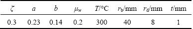
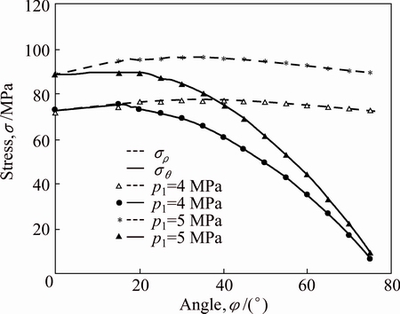
Fig. 4 Curves of stress distribution in free deformation zone during die-fillet forming
When �� is 0��, sin ��=0 occurs in the denominator of Eq. (10), and thus the limit calculation is necessary to obtain the limit of the following equation:

 .
.
According to  rule, ���� and ���� at the vertex of the spherical cap (��=0��) can be solved as follows:
 .
.
According to the preceding expression, the sheet is in equibiaxial tension stress state at the vertex of the spherical cap.
If the shape of the punch is adjusted, and uniformly distributed pressure pj is placed on the sheet metal by the granule medium, then ���� and ���� can be denoted as
 (15)
(15)
Referring to the parameters in Table 1 and assuming that pj=4 MPa, pj=5 MPa and H=40 mm, the distribution curves of ���� and ���� are obtained, as shown in Fig. 5, which greatly differ from those in Fig. 4 (non-uniformly distributed pressure). The variation trends of ���� and ���� are symmetrical to the horizontal medial axis, and the difference between them is the result of frictional stress.
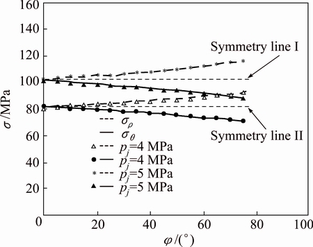
Fig. 5 Curves of stress distribution under uniformly distributed pressure
If ��w=0, Eq. (15) becomes
 (16)
(16)
Then, the free deformation zone of the deformed part is in the equibiaxial tensile stress state, and the meridional and circumferential stress values are determined by pj. R and t are consistent with those in hydroforming with the characteristics of uniform internal pressure and frictionless to sheets [19]. The stress curves of ���� and ���� in this state are merely the horizontal symmetric line, as shown in Fig. 5. When the friction is ignored and internal pressure is uniform, the forming mechanics of PGMF technology are evolved into the hydroforming. It can be seen that the theoretical research on PGMF technology considering friction and non-uniform internal pressure has universal significance, and the hydroforming is a special case of this process.
3.2 Forming stage of straight wall of parts
The forming stage of the straight wall of the cylindrical parts is shown in Fig. 6. When H��rd+rb, the wrap angle ��=90��. Meanwhile, the bottom shape of the part is close to the hemisphere whose radius is R=rb.
When the initial height of the granule medium is H0, and the thickness of the sheet metal is ignored, according to the invariability of the granule medium volume, the following expression is obtained:
 .
.
Then, the expression of X is obtained as follows:
 .
.
where X may be either a positive or a negative value. When the value is positive, the punch is above the surface of the flange (the position denoted in Fig. 6); when the value is negative, the punch inserts into the cavity of the part. To analyze the entire spherical cap with free deformation, the lowest position of the punch discussed in this work is the junction surface of the spherical cap and the straight wall (the horizontal section through point D vertical to the z-axis).
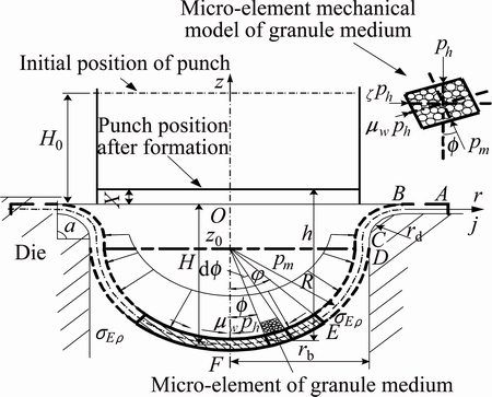
Fig. 6 Mechanical analysis of free deformation zone (��=90��)
Then, for the part with forming height H, the pressure-transfer distance h at any point is
 .
.
According to Eq. (2), ph at this position can be obtained as follows:
 (17)
(17)
Based on the deduction process in the forming stage of the die fillet, the following expressions are obtained:

 (18)
(18)


 (19)
(19)
where ph is denoted by Eq. (17).
If the sheet sustains the uniform internal pressure pj, the meridional and circumferential stresses can be denoted as
 (20)
(20)
If ��w = 0, Eq. (20) can be degenerated into the form of hydroforming [22] and expressed as
 (21)
(21)
HGMF technology can improve the drawing performance of sheet metal. Firstly, the friction between the granule medium and sheet metal is characterized as active friction, and the internal stress of the straight wall is reduced by the active friction distributed at the bottom and the straight wall of the part; thus, the risk of fracture is reduced. Secondly, the non-uniform distribution of internal pressure improves the plastic forming performance of the sheet metal by changing its stress state. Thirdly, during the free-drawing process, the spherical cap at the bottom bears most of the drawing forces; thus, the stress concentration at the punch fillet in the deep-drawing with traditional rigid punch can be avoided effectively.
4 Deep-drawing instability model and effect of parameters
According to Ref. [10], instability occurs when the critical meridional stress ��cr fits the following condition:
 (22)
(22)
where r is the plastic strain ratio of the material.
Suppose that ��=��0, the meridional stress ���� reaches the extreme value ����(��0). Set ����(��0)=��cr, and the relation equation of the parameters for the fracture instability of sheet metal in the HGMF technology is obtained based on Eqs. (11), (18), and (22).
The forming stage of the die fillet of the part is expressed as


 (23)
(23)
where M, N and I are the same as those in Eq. (11).
The forming stage of the straight wall of the part is expressed as


 (24)
(24)
where M and N are the same as those in Eq. (2), and
 .
.
In the case of the forming stage of the die fillet, the effect of the parameters such as n, r and ��w on the fracture instability of the sheet metal in the HGMF technology is studied. The critical pressure of the punch is defined as pc when critical fracture occurs. Refer to Table 1 and set H0=70 mm, ��0=��/6, and refer to the actual sampling ranges of the forming parameters and the change law of pc under different deep-drawing height H.
Figure 7 shows the evolution of pc according to H at different n. The result indicates that pc gradually increases and tends to be constant with the deep-drawing of the part. Overall, as n increases, pc slightly decreases with the increase of H, but the variation amplitude is small.
pc increases with the increment of r, and the amplitude increases with the rising H, as shown in Fig. 8.
��w has an obvious effect on pc, and pc increases with the increment of ��w. The increase in amplitude increases with the increase in H, which finally tends to be constant, as shown in Fig. 9.
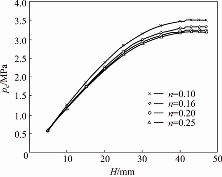
Fig. 7 Influencing curves of n (r=1, ��w=0.12)
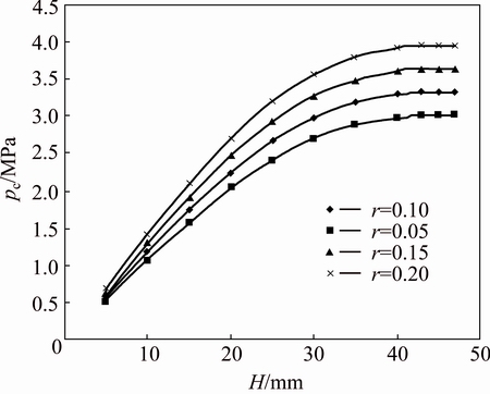
Fig. 8 Influencing curves of r (n=0.16, ��w=0.12)
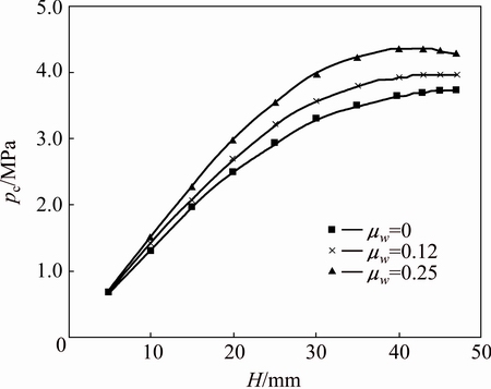
Fig. 9 Influencing curves of ��w (r=1, n=0.16)
pc increases with the increase of ��w and r but decreases with n, as shown in Figs. 7-9. Moreover, the impact order on pc from high to low is r, ��w, n.
In the HGMF technology for sheet metal, maintaining the pressure of the punch within the critical value is necessary to ensure the drawing feasibility. To improve the qualification rate of drawing parts, the value of pc should increase as much as possible. The preceding analysis shows that in the sheet metal with a small value of n and large values of r and ��w can be adopted, which is beneficial to deep-drawing.
In the forming stage of the straight wall during free deep-drawing, the bottom of the part is basically hemispherical and nearly constant. ph is unrelated to H and is only associated with H0 (see Eq. (24)). Consequently, pc is a constant value at this stage, which is consistent with the fact that pc tends to be constant with the increase in forming height H in the forming stage of the die fillet (as shown in Figs. 7�C9).
5 Experimental verification
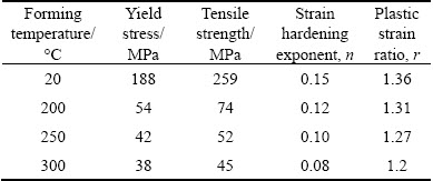
To verify the theoretical results, an experiment of deep-drawing forming for the cylindrical part based on the HGMF technology was conducted on AZ31B magnesium alloy sheet, and the experimental device is shown in Fig. 10(a). The performance parameters of AZ31B magnesium alloy sheet were obtained by electronic universal testing machine InspektTable100, as shown in Table 2.
Table 2 Material properties of AZ31B sheet (strain rate is 0.01 s-1)
The experiment was conducted using the 3150 kN hydraulic machine, and the diameter of the punch is 70 mm. Other relevant forming parameters of the experiment are shown in Table 1. The initial height of the granule medium is 70 mm, and the deep-drawing velocity 1 mm/s [14]. When the pressure of the punch exceeds the critical value, the fracture instability of the part occurs, as shown in Fig. 10(b). When the pressure of the punch is controlled within the critical value, the part with limit drawing ratio (LDR) of 2.41 can be successfully obtained, as shown in Fig. 10(c).
The experimental pressure values of the punch are compared with the theoretical pressure values of the critical fracture under the preceding two conditions (as shown in Fig. 11). The theoretical analysis can guide the experiments effectively.
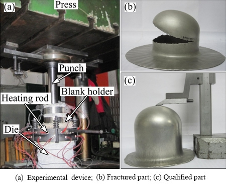
Fig. 10 Experimental device for deep-drawing and formed parts on AZ31B magnesium alloy
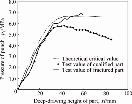
Fig. 11 Comparison between theoretical curves of critical punch pressure and experimental ones by HGMF technology
6 Conclusions
1) On the basis of the pressure-transfer attenuation law of solid granule medium, plastic mechanical analysis is conducted in the free deformation zone of the cylindrical parts of sheet metals based on HGMF technology, and the analytical expressions of the stress distribution at any point of the zone in the female die fillet forming stage and the straight wall forming stage are eventually obtained, which are associated with the parameters of the punch pressure, the initial medium height, the friction coefficient between the granule medium and the sheet.
2) Based on the analytic expression of the stress distribution in the free deformation zone, the relation equation of the critical pressure of the punch is established and combined with fracture instability theory. The critical pressure increases with the increment of the friction coefficient between the granule medium and sheet metal ��w, as well as the plastic strain ratio r, whereas it decreases with the increase of the material-hardening exponent n. Furthermore, the impact on pc from high to low order is r, ��w, n. Finally, the instability theory is verified by the hot deep-drawing experiment for cylindrical parts with the HGMF technology on an AZ31B magnesium alloy sheet, and the LDR of 2.41 is obtained.
References
[1] POURBOGHRAT F, VENKATESAN S, CARSLEY J E. LDR and hydroforming limit for deep drawing of AA5754 aluminum sheet [J]. Journal of Manufacturing Processes, 2013, 15(4): 600-615.
[2] PALUMBO G, PICCININNI A. Numerical-experimental investigations on the manufacturing of an aluminium bipolar plate for proton exchange membrane fuel cells by warm hydroforming [J]. The International Journal of Advanced Manufacturing Technology, 2013, 69: 731-742.
[3] LANG Li-hui, CAI Gao-shen, LIU Kang-ning, Alexandrov S, Du Ping-mei, Zheng Hang. Investigation on the effect of through thickness normal stress on forming limit at elevated temperature by using modified M-K model [J]. International Journal of Material Forming, 2015, 8(2): 211-228.
[4] Ho C, Muammer K, Jun N. A study on the analytical modeling for warm hydro-mechanical deep drawing of lightweight materials [J]. International Journal of Machine Tools & Manufacture, 2007, 47(11): 1752-1766.
[5] SHAO Zong-ke, HUANG Zhong-guo, JIN Shun-yao, LEI Kun, YUAN Qing-hua. Influence of single-direct and direct-reverse SPF on properties of TC4 alloy negative-angle parts [J]. Journal of Aeronautical Materials, 2013, 33(1): 1-6. (in Chinese)
[6] WU Xiao-wei, WANG Yong, JIN Quan-lin, MA Zhao-li, FENG Shuang-sheng, LIANG Hai-jian, WU Xiao-wei, WANG Yong, Jin Quan-lin, Ma Zhao-li, Feng Shuang-sheng. Research on quick superplastic forming for aluminium alloy sheet [J]. Materials Science Forum, 2013, 735: 301-306.
[7] Zhang Shi-hong, Zhou Li-xin, Wang Zhong-tang, XU Yi. Technology of sheet hydroforming with a movable female die [J]. International Journal of Machine Tools & Manufacture, 2003, 43(8): 781-785.
[8] LIU Xiao-jing, CONG Yan-li, LI Feng, XU Yong-chao, YUAN Shi-jian. Effects of independent radial pressure loading paths on cup thickness distribution [J]. Journal of Central South University: Science and Technology, 2010, 41(3): 917-922. (in Chinese)
[9] Wang Zhong-jin, Li Yi. Formability of 6k21-t4 car panel sheet for viscoelastic-plastic flexible-die forming [J]. Journal of Materials Processing Technology, 2008, 201(1-3): 408-412. (in Chinese)
[10] BARIANI P F, BRUSCHI S, GHIOTTI A, LUCCHETTA G. An approach to modelling the forming process of sheet metal-polymer composites [J]. CIRP Annals��Manufacturing Technology, 2007, 56(1): 261-264.
[11] LIN Zhong-qin, SUN Cheng-zhi, CHEN Guan-long, YU Hai-yan. Analytical and experimental studies on critical blank-holder forces in cylindrical cup deep drawing [J]. Journal of Shanghai Jiaotong University, 2004, 38(S): s101-s107. (in Chinese)
[12] ZHANG Zhi-yuan, ZHAO Sheng-dun, ZHANG Yong, Wang Ji, Yuan Jian-hua. Analysis on various factors of rupture instability during cylindrical cups deep drawing [J]. Chinese Journal of Mechanical Engineering, 2007, 43(3): 154-159. (in Chinese)
[13] YOSSIFON S, TIROSH J. Rupture instability in hydroforming deep drawing process [J]. International Journal of Mechanical Sciences, l985, 27(9): 559-570.
[14] CAO Miao-yan, ZHAO Chang-cai, DONG Guo-jiang, HAO Hai-bin. Mechanical analysis of deep drawing of cylinder based on solid granules medium forming technology [J]. Journal of Mechanical Engineering, 2013, 49(2): 42-48. (in Chinese)
[15] ZHAO Chang-cai, CAO Miao-yan, XIAO Hong, DONG Guo-jiang, HAO Hai-bin. Solid granular medium drawing process parameters of magnesium alloy sheet [J]. The Chinese Journal of Nonferrous Metals, 2012, 22(4): 991-999. (in Chinese)
[16] CAO Miao-yan, DONG Guo-jiang, ZHAO Chang-cai. Research on pressure-transfer characteristics in the solid granule medium forming based on the discrete element method [J]. Journal of mechanical engineering, 2011, 47(14): 62-69. (in Chinese)
[17] LI Peng-liang, ZHANG Zhi, ZENG Yuan-song. Study on titanium alloy spinner based on solid granules medium forming [J]. Forging & Stamping Technology, 2012, 37(5): 60-63. (in Chinese)
[18]  M, MERKLEIN M. Numerical simulation of hydro forming at elevated temperatures with granular material used as medium compared to the real part geometry [J]. International Journal of Material Forming, 2010, 3(1): 279-282.
[19] LANG Li-hui, LIU Kang-ning, CAI Gao-shen, GUO Chan. Numerical research on forming technology of complicated taper-shaped part of TC4 titanium alloy by thermal deep drawing with heated media [J]. Aeronautical Manufacturing Technology, 2013, 16: 109-112. (in Chinese)
[20] ZHANG Ling-yun, YUAN Hai-huan. New technology of solid granule medium deep drawing and forming die design [J]. Forging & Stamping Technology, 2010, 35(1): 93-95. (in Chinese)
[21] HOSFORD W F, CADDELL R M. Metal forming mechanics and metallurgy [M]. 2nd ed. New York: Cambridge University Press, 1993.
[22] HU Shi-guang, CHEN He-zheng. Engineering analysis of cold-press forming on sheet metals [M]. Beijing: Beihang University Press, 2004: 109-195. (in Chinese).
������1���Գ���2��������3����ʢ��1
1. ��ɽ��ѧ ��е����ѧԺ���ػʵ� 066004��
2. ��ɽ��ѧ �Ƚ���ѹ���μ������ѧ�������ص�ʵ���ң��ػʵ� 066004��
3. ��ɽ��ѧ ��������ԴѧԺ���ػʵ� 066004
ժ Ҫ��������̬����������ʳ��ι��նԽ������Ͳ�μ�����չ���о����õ���ı��ι����е�Ӧ���ֲ�����������ϰ������ʧ�����۸������ɱ�������ͷ�ٽ����ѳ���ѹ���Ľ�������ʽ���о�����������������������е�����Ħ��ЧӦ����ѹ�Ǿ��ȷֲ�������������߰�ĵij������ܣ���ͷ�ٽ����ѳ���ѹ��������������ļ�Ħ�������Ͳ�������Ӧ��ȵ����Ӷ������������Ӳ��ָ�������Ӷ��½��������ضԳ�ͷ�ٽ����ѳ���ѹ��Ӱ���ɴ�С��˳��Ϊ����Ӧ��ȡ�Ħ��������Ӳ��ָ���������AZ31Bþ�Ͻ���HGMF���������ʧ�����۽�����֤��
�ؼ��ʣ���̬��������ѹ�����Σ����ʧ�ȣ�Ͳ�μ�
(Edited by Wei-ping CHEN)
Foundation item: Projects (51305385, 51305386) supported by the National Natural Science Foundation of China; Project (QN20131080) supported by the Science Research Youth Foundation of Hebei Province Universities, China
Corresponding author: Sheng-fu YANG; Tel: +86-13333286526; E-mail: yangshengfu@ysu.edu.cn
DOI: 10.1016/S1003-6326(16)64335-2

