
Experimental and finite element analysis for fracture of coating layer of galvannealed steel sheet
S. I. KIM1, J. U. HER2, Y. C. JANG2, Y. LEE2
1. Sheet Products and Process Research Group, POSCO Techology Research Laboratory, Gwangyang, Korea;
2. Department of Mechanical Engineering, Chung-Ang University, Seoul, 156-756, Korea
Received 21 April 2010; accepted 10 September 2010
Abstract: Mechanical properties of galvannealed (GA) steel sheet used for automotive exposed panel and predicted failure phenomenon of its coating layer were evaluated using finite element method. V-bending test was performed to understand better the fracture of coating layer of GA steel sheet during plastic deformation. Yield strength of the coating layer was calculated by using a relative difference between hardness of coating layer measured from the nano-indentation test and that of substrate. To measure shearing strength at the interface between substrate and coating layer, shearing test with two specimens attached by an adhesive was carried out. Using the mechanical properties measured, a series of finite element analyses coupled with a failure model was performed. Results reveal that the fracture of coating layer occurs in an irregular manner at the region where compressive deformation is dominant. Meanwhile, a series of vertical cracks perpendicular to material surface are observed at the tensile stressed-region. It is found that 0.26-0.28 of local equivalent plastic strain exists at the coating and substrate at the beginning of failure. The fracture of coating layer depends on ductility of the coating layer considerably as well.
Key words: galvannealed steel sheet; fracture simulation; coating layer; finite element analysis, failure model
1 Introduction
In recent years, there has been a growing demand for corrosion resistant sheet steel with superior mechanical properties in the automotive industry. Especially, the demand for formability and surface quality has led to the application of a great amount of ultra low carbon interstitial free (IF) steel to galvanizing and galvannealing as base steel [1-4].
The coated steel sheets are very popular materials for manufacturing both unexposed and exposed panels in the automotive body. The coated steel sheet is of strong points in corrosion resistance, surface quality, formability, reasonable costs and environmental friendliness. The coated steels are usually categorized into three groups: galvanized (GI) steel, electro- galvanized (EG) steel and galvannealed (GA) steel. It is well known that the GA steel is superior to other coated steels in terms of the corrosion resistance, surface quality, formability, reasonable costs and environmental friendliness except the fracturing features of coating layer. Hence, many researches [5-11] have been interested in enhancing formability of the GA steel together with the fracturing features of the coating layer at the same time.
In general, failure phenomenon is divided into a powdering that failure occurs in coating layer itself and a flaking that substrate and coating layer failure simultaneously. The formability response of material changes due to increased frictional conditions at the sheet/tool(die) interface and the mechanical properties of substrate. Coating powder and/or flake built up on die surfaces leads to changes in frictional behavior and poor appearance on surfaces. Since the GA steel has Zn-based coatings on its surface, zinc coatings fail as a result of removal of powdering and/or flaking during forming [7-8, 11]. Fe-Zn intermetallic phases in the coating layer are considered to be brittle. Therefore, as formability increases, fracture in the coating layer occurs during forming.
To enhance the formability and surface quality of the GA steel sheet, the previous works [5-13] focused on controlling several factors such as grain size, crystallographic orientation, temperature, coating thickness and phase composition of the intermetallic layer. However, there has been no report which analyzes the fracturing features in coating layer quantitatively dependent on the mechanical properties of intermetallic layer.
In this study, we examined powdering based on the V-bending test which gave large local deformation. To investigate powdering quantitatively during the test, we also carried out a series of finite element analyses. We first performed tensile test of substrate (steel sheet), nano-indentation of coating layer and measured the shear strength at the interface. Using a failure model, we then carried out FE simulation of failure at a region where local deformation is significant. We investigated the behavior of substrate, coating layer and interface when the strain for failure in FE simulation varied.
2 Experimental
2.1 Specimen
The steel utilized in this study was a cold-rolled ultra low carbon Ti and Nb added interstitial free (IF) steel, and the chemical compositions are listed in Table 1. Laboratory- scale ingot was obtained by a laboratory vacuum induction melting and hot-rolled into sheet with 3.2 mm in thickness. The hot-rolled sheets were cold-rolled into sheet with 0.7 mm in thickness. The cold-rolled steel sheets were annealed at 800 °C for 3 min in infrared furnace. Continuous galvannealing heat treatment was conducted by a new state-of-art galvanizing simulator.
The specimen used in the V-vending and nano- indentation test was the 340MP-grade GA steel sheet which was baking hardened. Dimensions of substrate and coating layer are listed in Table 2. The coating layer of galvannealed steel sheet is composed of three different phases, FeZn13 (monoclinic structure), FeZn10 (hexagonal structure) and Fe3Zn10 (body centered cubic structure). Hence the mechanical properties of the coating layer are also influenced by the volume fraction of the phases. It is well known that the FeZn10 and Fe3Zn10 are the brittle phases, while the FeZn13 phase is the most ductile [14-15]. However, the FeZn10 and Fe3Zn10 phases take about 95% in the Fe-Zn coatings and consequently they determine mechanical properties of the whole coating layer. Thus, the three phases are not distinguished and uniform mechanical property in the coating layer is assumed.
Table 1 Chemical compositions of utilized steel (mass fraction, %)

Table 2 Dimension of specimen

2.2 Stress―strain curve of substrate
We conducted a uniaxial tensile test using equipment, ZWICK? to measure stress―strain curve of the substrate. Gauge length of the specimen was 50 mm and its width was 25 mm and the cross head speed was 10 m/min. Fig.1 shows the measured stress―strain curve of the substrate. Elastic modulus (210 GPa), yield strength (223 MPa), ultimate tensile strength (341 MPa) and failure strain (0.41) of the specimen were obtained from the stress―strain curve.

Fig.1 Stress―strain curve of substrate
2.3 Nano-indentation test
Since coating layer is composed of many micro-sized inter-metallic compounds, measuring its yield stress directly is very difficult. Hence we obtain its yield strength through converting its surface hardness to yield strength. For this purpose, we measured its hardness at regions arbitrarily selected using nano-indentation test. Table 3 shows the hardness of specimen measured by the nano-indentation test.
In this study, it is assumed that the yield strength of coating layer is proportional to its hardness, Hn, which is as follows:
σy|s=C?Hn (1)
where C (0.9) is a material constant and Hn is a nano indentation hardness. It has been found that average yield strength of coating layer is about 390 MPa.
2.4 Shear strength test of coating layer
In this study, we carried out shear strength test to evaluate the interface strength between substrate and coating layer. The test procedure adopted in this study is modified from standard test procedure (ASTM5659) which evaluates the adhesion of steel sheets. Many researchers estimated shear strength of coating layer with the similar method mentioned above [16-18]. Note that TSUNEKAWA et al [19] reported that the cohesive strength of steel was improved when it is in hot-dip aluminum coatings with a thin reaction layer of approximately 5 μm.
Table 3 Measured hardness of coating layer and substrate

The failure shear strength at the interface indicates exfoliation strength of the interface. To measure failure shear strength at the interface between substrate and coating layer, we attached two specimens using adhesive which has higher bonding strength than substrate and coating layer, and conducted the test using a conventional tensile testing machine. Fig.2 shows the schematic diagram of specimen configuration used for measuring failure shear strength at the interface. The cross head speed of this test was 50 mm/min.

Fig.2 Schematic diagram of specimen configuration for shear test
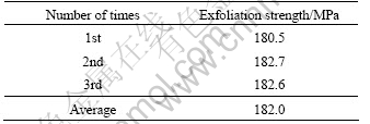
We measured the shear stress―strain curve until the substrate and coating layer were separated each other. It was assumed that the type of glue used did not affect the results. The maximum value of the curve corresponds to failure shear strength of the interface. To secure reproducibility of this test results, we performed this test three times under the same test condition. Exfoliation strength at the interface is listed in Table 4. Uniaxial yield stress, σy|i of the interface is calculated by converting pure shear yield strength, k, using Eq.(2):
σy|i= (2)
(2)
Table 4 Exfoliation strength at interface
2.5 V-bending test
There are many test types for evaluating formability of steel (Double-Olsen, 180° U-bend, swift-cup, draw bead and 90° V-bending test). 90° V-bending test was selected and performed with the cross head speed of 10 mm/min. Fig.3 shows the dimensions of die and punch of V-bending test. The radius of punch tip is 1 mm. The specimens with 110 mm in length and 60 mm in width were machined. Thickness of specimen was 0.7 mm. During V-bending test, specimen was deformed gradually into V-shape and consequently the specimen has a highly strained area at its center. The test procedure adopted in this study follows the recommendation made by the automotive manufacturers (Honda, Nissan and Toyota). Fig.4 illustrates the fracture morphologies of coating layer at the inner center area and the outer center area of V-bended specimen. We can observe different behaviors of the coating layer and interface. In compressed area, powdering occurs in an irregular manner at the interface. Meanwhile, powdering occurs at the interface with almost vertical toward substrate [7-8, 11].

Fig.3 Schematic diagram of specimen configuration for shear test

Fig.4 Fracture morphologies of coating layer at inner center area (a) and outer center area (b) of V-bended specimen
3 Finite element analysis
3.1 Finite element mesh of specimens
Fig.5 shows the finite element mesh employed in the present study. A quarter of the specimen was analyzed due to the geometry of the specimen and the loading condition shown in Fig.5(a). Dense meshes are generated in the center of the specimen and spare meshes are generated in other region. The number of elements used is 5 560 and element type for the specimens is C3D8R (8-node linear brick, reduced integration with hourglass control) (see Fig.5 (b)). The specimen is divided into three regions which are substrate, coating layer and interface. Fig.5(c) shows the dimension and layer shape of the specimen.
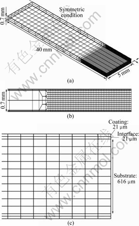
Fig.5 Mesh configuration of entire specimen (a), transition mesh of specimen (b) and dimension of specimen cross section (c)
3.2 Mechanical property assigned to finite element analysis
Table 5 lists the experimentally measured values, referred values, calculated values and assigned values of substrate, interface and coating layer for FE analysis. The coating layer is very closely located to the substrate, so we applied elastic modulus of the coating layer to the substrate. Elastic modulus of the coating layer in the Refs.[4-5, 15] was used. We applied these values to FE analysis.
The yield strength of substrate is small and half of its ultimate tensile strength. In other words, a ratio of ultimate tensile strength to yield strength is about 1.5. We applied this ratio to the coating layer and the interface. The failure strain of coating layer and the interface might vary case by case. Three cases are considered in this study. Mechanical properties used in finite element analysis are summarized in Table 5. Fig.6 illustrates the stress―strain curve for each case assigned for the finite element simulation.
3.3 Failure model
In FE simulation of failure, element removing scheme was adopted. Failure implies a complete loss of load carrying capacity of an element which stems from progressive degradation of the stiffness of the element. In the case of failure, stiffness degradation initiates when the equivalent plastic strain. For example, it reaches a specified strain for failure, εf, of material. In this study, an element under severe local deformation condition is assumed to fail fully when the equivalent plastic displacement of the element reaches failure strain, εf. This failure simulation method was applied to the coating layer and interface as well.
Once stiffness degradation initiates, softening of the yield stress starts based on a scalar damage approach. Softening response is described by a stress―displacement relation. To minimize the effect of mesh size on the evolution of element removing, a characteristic length is computed on the basis of element geometry.
3.4 Plastic strain distribution with failed elements
The upper surface of the specimen is under compression and the opposite surface is under tension. Fig.7 shows the finally deformed shape of the specimen and plastic strain to x-axis. No powdering on the coating layer is observed for Case 1, but some powdering is observed for Case 2 and Case 3. Top side indicates the region under compressive stress and bottom side indicates the region under tensile stress. Failure occurs on the upper surface of the specimen as the punch pushes the specimen down in the coating layer and the interface. The failure on the lower surface occurs later. This result is corresponding to the observation reported in Refs.[13, 20]. The plastic strain on the compressed area is greater than that on the tensioned area. The powdering phenomenon decreases as the failure strain of the coating layer increases. This indicates that the development of GA steel which has a stress―strain curve like Case 3 might be necessary to secure formability in the secondary manufacturing process.
Table 5 Mechanical properties of specimen used for finite element analysis


Fig.6 Uniaxial stress―strain curves for each case assigned for FE analysis

Fig.7 Plastic strain contour of deformed specimen: (a) Deformed shape of specimen; (b) Case 1; (c) Case 2; (d) Case 3
4 Conclusions
1) The fracture of coating layer for galvannealed (GA) steel sheet was analyzed using V-bending test and finite elements analysis. To evaluate the material property of coating layer with high reliability, various testing methods such as uniaxial tension test, nano-indentation and shear strength test were performed.
2) When tensile deformation mode is activated at the coating layer and equivalent local plastic strain is more than 0.28, failure of coating layer occurs. Meanwhile, when compressive deformation mode is activated at the coating layer and equivalent local plastic strain is beyond 0.26, failure of coating layer was observed. Development of GA steel which has a stress―strain curve like Case 3 might be necessary to secure formability in the secondary manufacturing process.
Acknowledgements
This research was supported by Basic Science Research Program through the National Research Foundation of Korea (NRF) funded by the Ministry of Education, Science and Technology (2009-0074936).
References
[1] JORDAN C E, OGGINS K M, MARDER A R. Interfacial layer development in hot-dip galvanneal coatings on interstitial free (IF) steel [J]. Metallurgical Transactions A, 1994, 25A: 2101-2109.
[2] KAGECHIKA H. Recent progress and outlook for zinc and zinc alloy coated steel sheets in Japan [C]// 7th International Conference on Zinc and Zinc Alloy Coated Steel Sheet: Galvatech '07. Osaka, Japan, 2007: 1-5.
[3] GOODWIN F E. An overview of North American zinc based sheet steel coatings production: Status and opportunities [C]// 7th International Conference on Zinc and Zinc Alloy Coated Steel Sheet : Galvatech '07. Osaka, Japan, 2007: 6-13.
[4] DILLEN R, de VYT A, XHOFFER C, LEUNIS E, CLAESSENS S, DHONT A. From substrate to coating: Micro and surface analysis techniques for the development of steel products [J]. Microchimica Acta, 2004, 145: 29-39.
[5] ALPAS A T, INAGAKI J. Effect of microstructure on fracture mechanisms in galvannealed coatings [J]. ISIJ International, 2000, 40(2): 172-181.
[6] NUNOMURA Y, TAKASUGI T. Plastic deformation and fracture behavior of galvannealed coating [J]. ISIJ International, 2003, 43(3): 454-460.
[7] BAE D C, CHOI Y M, CHANG S, SHIN J C. Improved powdering resistance of hot-dip galvannealed steel sheets [C]// GALVATECH '92. Amsterdam: Stahl and Eisen. 1992: 132.
[8] JAGANNATHAN V. The influence of coating characteristics on the powdering and corrosion resistance of galvanneal coated steel sheet [C]// GALVATECH '92. Amsterdam: Stahl and Eisen. 1992: 127.
[9] HONG M H. Correlation between the microstructure of galvannealed coatings and the defoliation during press forming [J]. ISIJ International, 2005, 45(6): 896-902.
[10] OCHIAI S, IWAMOTO S, TOMITA T, NAKAMURA T, OKUDA H, TANAKA M, MOJO M. Multiple-cracking phenomenon of the galvannealed coating layer on steels under thermal and tensile stresses [J]. Metallurgical and Materials Transactions, 2005, 36A: 1807-1816.
[11] CHAKRABORTY A, BHATTACHARJEE D, PAIS R, RAY R K. Effect of galvannealing power on the texture and powdering resistance of industrially produced galvannealed coating on interstitial free steel [J]. Scripta Materialia, 2007, 57: 715-718.
[12] GARZA L G, VAN TYNE C J. Friction and formability of galvannealed interstitial free sheet steel [J]. Journal of Materials Processing Technology, 2007, 187-188: 164-168.
[13] LEE K., LEE I, LEE C, AHN H. In-situ observation in a scanning electron microscope on the exfoliation behavior of galvannealed Zn-Fe coating layers [J]. Surface and Coatings Technology, 2007, 201: 6261-6266.
[14] RANGARAJAN V, JAGANNATHAN V, RAGHAVAN K S. Influence of strain state on powdering of galvannealed sheet steel [J]. SAE Transactions, 1996, 105: 68-75.
[15] FOCT J, IOST A, REIMONT G. Mechanical behavior of zinc coating [C]//. The Physical Metallurgy of Zinc Coated Steel, Warrendale, PA, USA: TMS, 1993: 21-30.
[16] HERTVELDT I, DECOOMAN B C, MESEURE K C. XHOFFER. The shear strength of galvannealed coatings on IF steels [J]. ISIJ International, 1999, 39: 1280-1288.
[17] IWAMOTO S, OCHIAI S, OKUDA H, INOUE T. Analysis of buckling and interfacial debonding of galvannealed coating layer on steel substrates under applied tensile strain [J]. ISIJ International, 2007, 47: 930-934.
[18] XU C, LIN Z Q, LI S H, ZHANG W G. Research on shear strength of galvannealed coatings [J]. Materials and Design, 2007, 28: 1668-1671.
[19] TSUNEKAWA Y, TAMURA S, OKUMIYA M, ISHIHARA N. Hot-dip coating of lead-free aluminum on steel structures with ultrasonic vibration [J]. Journal of Materials Science and Technology, 2008, 24: 41-44.
[20] HAUW B, DUBAR L, OUDIN J. Improvement of stamping computations by means of the identification of the bulk behaviour of coatings: Application to galvanized sheets [J]. Journal of Materials Processing Technology, 1999, 94: 23-29.
(Edited by LI Xiang-qun)
Corresponding author: Y. LEE; Tel: +82-2-8245256; E-mail: ysl@cau.ac.kr

