
Cup-drawing formation of steel sheet with nickel coating by
finite element method
ZHANG Xiao-bing(张小兵), LONG Shi-guo(龙士国), MA Zeng-sheng(马增胜),
PAN Yong(潘勇), ZHOU Yi-chun(周益春)
Key Laboratory of Low Dimensional Materials and Application Technology, Ministry of Education,
Faculty of Material and Photoelectronic Physics, Xiangtan University, Xiangtan 411105, China
Received 15 July 2007; accepted 10 September 2007
Abstract: The finite element method (FEM) simulation of deep-drawing of steel sheet with nickel coating based on the solid element and dynamic explicit method was reported. Penalty function method was used to treat the contact algorithm. The friction between the punch and coating sheet was based on a Coulomb formulation. The combination of coating and substrate was defined as tied with failure contact. The results of the simulation illustrate that the steel sheet and the nickel coating do not delaminate at the interface. The stress field of the nickel coating is more complicated than that of the steel substrate. Furthermore, it is found that the punch-nose radius is the most unsubstantial part for the intensity of the entire deep-drawing part and the thinnest part, it is a dangerous zone for the break. At this zone, the thickness thinning of the steel sheet and the nickel coating are up to 4.8% and 6.7%, respectively. Meanwhile, it is found that the curve of the variable blankholder force (VBHF) designed can improve the formability of sheet.
Key words: electrodeposited nickel coating; solid element; finite element method; variable blankholder force
1 Introduction
The coated steel sheet is an important type of structural-function material, it can be prepared by bilaterally electrodepositing nickel on the low carbon steel sheet. It is found that this material has good corrosion resistant, attractive toughness and excellent plasticity which offers the potential for advanced structure applications. With the development of this material, the process technique that nickel is firstly electrodeposited on the steel substrate, and then the coating and substrate are wholly formed instead of the process technique that the steel is firstly formed and then the production surface is electrodeposited nickel coating. Therefore, the formality of sheet with coating is an important process technology[1-3].
Nowadays, with the applications and development of finite element, many researchers have used the FEM method to simulate the deep drawing process of sheet, but deep drawing of the inhomogeneous material has been studied among a few researchers[4-6]. TAKUDA et al[7] have predicted the forming limit of Fe/Al laminated composite sheets in deep drawing. LEE et al[8] have studied the formability and frictional behavior of coated sheets according to the blank holding, but they did not consider the interface intensity.
In the present work, the deep drawing process of the nickel-coated sheet was simulated by LS-DYNA software using solid elements. An attempt has been made to investigate the rules of the stresses field and material flow of the sheet. Moreover, the effect of blankholder force (BHF) was also studied and a VBHF curve was designed to improve the formability of sheet.
2 Problem description and FEM model
Because of its simplicity, the cup-drawing process of steel sheet coated nickel is invested and due to the shape symmetry, only one quarter of the geometry has been modeled. The geometry of the tools and the sheet in the deep-drawing process is shown in Fig.1. The detailed parameters are listed in Table 1.
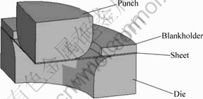
Fig.1 Schematic diagram of one quarter profile of problem model
Table 1 Parameters in first cup-drawing produce
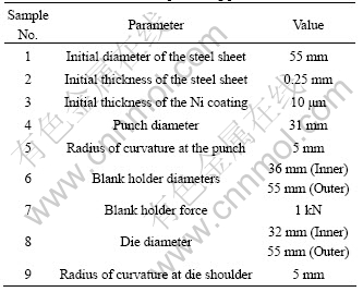
The mechanical properties of the sheet coated nickel are listed in Table 2.
Table 2 Mechanical properties of the material
An FEM based software LS-DYNA is used in the present work to simulate the deep drawing process. LS-DYNA is a nonlinear dynamic simulation software, particularly designed to analyze the non-linear dynamic response of three-dimensional structures, which can simulate different types of sheet metal forming processes like deep drawing, stretch forming, bending, etc, to predict the stresses, strain, thickness distribution, punch load and effect of various design parameters of tooling on the process efficiency and final product [9-11].
In the deep drawing processes of this material, the coating/substrate composite may delaminate or crack in the interface. The combination of coating with substrate was considered a contact in the simulation, defined as “tied with failure contact”, that is, before it arrives the deterioration, the contact surface or node ties with the target, and after the arrived deterioration, contact surface or node separate from the target and may slide each other.
A penalty-based contact model is considered in the computations where the friction effects are described via the Coulomb law. Similar lubrication conditions between the sheet and different tools were considered in the simulations. Therefore, for simplicity, a constant friction coefficient was used in the simulations. Moreover, to prevent wrinkling in the sheet drawing process, a blank holder force during the forming process is assumed for each case, in these analyses, the substrate and coating are discretized with 8-node ‘brick’ solid elements from the element library of DYNA 3D code, which presents the macroscopic mesh distortion in a better way, while different tools are only meshed with surface elements on their contours since they are assumed to be rigid.
3 Results and discussion
3.1 Stress field and thickness distribution
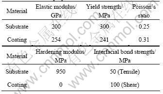
The equivalent stresses distribution of the substrate and the coating with drawing depth of 13 mm ware shown in Fig.2, the maximum equivalent stress of the substrate is found at the die radius, up to 604 MPa, which surpasses the yield stress of the material, they are presumably attributed to the strain hardening of the material. Compared with the substrate, the variation of the equivalent stress of the coating was basically the same as that of the substrate, but the stress distribution of the coating is more complex during the deep drawing process, which appears as some stress at some place.
Fig.2 Equivalent stresses of substrate(a) and coating(b) with drawing depth of 13 mm
The thickness variation of the substrate and the coating in Fig.3 are listed in Table 3, which shows that the sheet in the flange (position d) would tend to thicken, the maximum thickness of the substrate could arrive at 0.283 mm, and the nickel coating could arrive at 11.1 μm. But the sheet would be drawn and thinned as it passed through the punch fillet profile.
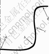
Fig.3 Schematic diagram showing position of thickness change
Table 3 Final thickness of sheet at different parts shown in Fig.3
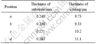
After deformation, the thinnest place is at the fillet of lower part of the cup (position b), The substrate thickness of this region is about 0.238 mm, and the nickel coating thickness of this region is about 9.33 μm. The thickness thinning of the steel sheet and the nickel coating are up to 4.8% and 6.7%, respectively, which are the danger zone for the break. General speaking, in the entire deformation process, the thickness of the substrate and the coating varies consistently. The upper part of the cup would be thicker than the lower part.
3.2 Influence of BHF
The BHF is one of the most important parameters to influence the sheet metal formability, which affects the material flow and stress distribution of the sheet. When the BHF is too low or too high, wrinkle or fracture may occur[12-13], respectively. Fig.4 shows the sheet wrinkle when the BHF is set to 0.5 kN. Because the VBHF technique can improve the formability of sheet, forming precision and surface quality, how to implement the VBHF technology has become one of the research emphases in the field of sheet metal forming[14-15].
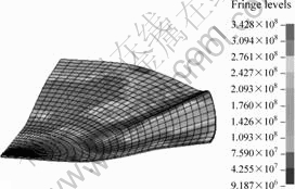
Fig.4 Distribution of equivalent stress at BHF=0.5 kN
According to the drawing theory, the reasonable variation rules of the BHF is accordant with the punch force in deep drawing, a curve of the VBHF is designed for numerical simulation based on the punch load-stroke curve (Fig.5) of the drawing process at BHF=1 kN . The special parameters are depicted in Fig.6.
The initial BHF is 0.5 kN, when the punch stroke is 10 mm, the BHF is 1 kN, at the end of deep drawing, the BHF is 0.6 kN. With both constant BHF and VBHF, the thickness variations of the substrate and the coating at the thinnest position are compared in Fig.7, which reveals that the thickness of the coating at the thinnest position increases from 9.33 to 9.39 μm and the thickness of the steel sheet at the thinnest position increases from 0.238 to 0.239 mm, respectively.
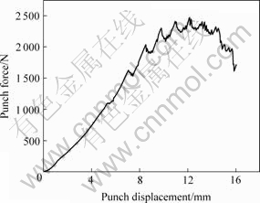
Fig. 5 Curve of punch force vs punch displacement
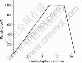
Fig. 6 Curve of VBHF for numerical simulation
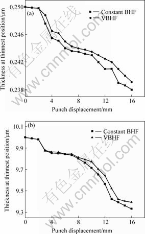
Fig.7 Thickness variations of sheet at thinnest position: (a) Substrate; (b) Coating
4 Conclusions
1) The thinnest part of the sheet is at the fillet of lower part of the cup and the thickness thinning ratio of the steel sheet and the nickel coating of this zone are 4.8% and 6.7%, respectively, which shows that the thinning ratio of the coating is higher than that of the steel sheet.
2) The VBHF technology can improve the formability of sheet, a curve of the VBHF designed can be used in the deep drawing process, which can decrease the maximum tensile stress along the punch direction and the danger for breaking.
References
[1] LONG S G, ZHOU Y C, PAN Y. Computation of deformation-induced textures in electrodeposited nickel coating[J]. Trans Nonferrous Met Soc China, 2006, 16(Special 1): s232-s238.
[2] ZHOU L Q, ZHOU Y C, PAN Y. Coating thickness variation during multistep drawing processes[J]. Journal of Materials Science letter, 2004, 39(2): 757-760.
[3] ZHOU L Q, LI Y P, ZHOU Y C. Forming limit of electrodeposited nickel coating in the left region[J]. Journal of Materials Engineering and Performance, 2006, 15(3): 287-294.
[4] MENEZES L F, TEODOSIN C. Three-dimensional numerical simulation of the deep-drawing process using solid finite elements[J]. Journal of Materials processing Technology, 2000, 97(1): 100-106.
[5] HU Jian-guo, JONAS J J, ISHIKAWA T. Finite element analysis of damage evolution and the prediction of the limiting draw ratio in textured aluminum sheets[J]. Journal of Materials Processing Technology, 2000, 103(2): 374-382.
[6] FERESHTEH-SANIEE F, MONTAZERAN M H. A comparative estimation of the forming load in the deep drawing process[J]. Journal of Materials processing Technology, 2003, 140(3): 555-516.
[7] TAKUDA H, FUJIMOTO K, HATTA N. Prediction of forming limit in deep drawing of Fe/Al laminated composite sheets using ductile fracture criterion[J]. Journal of Materials Processing Technology, 1996, 60(2): 291-296.
[8] LEE J M, KO D C, LEE K S, KIM B M. Identification of the bulk behavior of coatings by nano-indentation test and FE-analysis and its application to forming analysis of the coated steel sheet[J]. Journal of Materials processing Technology, 2007, 187/188(1): 309-313.
[9] KISHOR N, RAVI KUMAR D. Optimization of initial Blank shape to minimize earring in deep drawing using finite element method[J]. Journal of Materials processing Technology, 2002, 130/131(1): 20-30.
[10] Chow C L, TAIL W H, CHU E. Computer simulation of sheet metal forming based on damage mechanics approach[J]. Journal of Materials processing Technology, 2003, 139(1/3): 553-558.
[11] MAMALIS A G, MANOLAKOS D E, BALDOUKAS A K. On the finite-element modeling of the deep-drawing of square sections of coated steels[J]. Journal of Materials processing Technology, 1996, 58(2/3): 153-159.
[12] LIN Zhong-qin, WANG Wu-rong, CHEN Guan-long. A new strategy to optimize variable blank holder force towards improving the forming limits of aluminum sheet metal forming[J]. Journal of Materials processing Technology, 2007, 183(2/3): 339-346.
[13] OBERMEYER E J, MAJLESSI S A. A review of recent advances in the application of blank-holder force towards improving the forming limits of sheet metal parts[J]. Journal of Materials processing Technology, 1998, 75(2): 222-234.
[14] DOEGE E, SOMMER N. Blank-holder pressure and blank-holder layout in deep drawing of thin sheet metal[J]. Advanced Technology of Plasticity, 1987, 11(10): 1305-1314.
[15] SHENG Z Q, JIRATHEARANAT S, ALTAN T. Adaptive FEM simulation for prediction of variable blank holder force in conical cup drawing[J]. International Journal of Machine Tools & manufacture, 2004, 44(3): 487-494.
Foundation item: Projects(05B008, 104014) supported by the Scientific Research Fund of Hunan Education Department, China; Project supported by Fok Ying Tong Education Foundation of Ministry of Education, China
Corresponding author: LONG Shi-guo; Tel: +86-13607325816; E-mail:longsg@xtu.edu.cn
(Edited by LONG Huai-zhong)

