J. Cent. South Univ. (2017) 24: 726-735
DOI: 10.1007/s11771-017-3474-0

Super-harmonic resonance of gear transmission system under stick-slip vibration in high-speed train
HUANG Guan-hua(�ƹڻ�)1, 2, XU Si-si(��˼˼)3, ZHANG Wei-hua(������)1, YANG Cai-jin(��̽�)1
1. State Key Laboratory of Traction Power (Southwest Jiaotong University), Chengdu 610031, China;
2. Beijing Haidongqing Electrical and Mechanical Equipment Co., Ltd, Beijing 101300, China;
3. CRRC Institute Co., Ltd, Beijing 100070, China
 Central South University Press and Springer-Verlag Berlin Heidelberg 2017
Abstract: This work deals with super-harmonic responses and the stabilities of a gear transmission system of a high-speed train under the stick-slip oscillation of the wheel-set. The dynamic model of the system is developed with consideration on the factors including the time-varying system stiffness, the transmission error, the tooth backlash and the self-excited excitation of the wheel-set. The frequency-response equation of the system at super-harmonic resonance is obtained by the multiple scales method, and the stabilities of the system are analyzed using the perturbation theory. Complex nonlinear behaviors of the system including multi-valued solutions, jump phenomenon, hardening stiffness are found. The effects of the equivalent damping and the loads of the system under the stick-slip oscillation are analyzed. It shows that the change of the load can obviously influence the resonance frequency of the system and have little effect on the steady-state response amplitude of the system. The damping of the system has a negative effect, opposite to the load. The synthetic damping of the system composed of meshing damping and equivalent damping may be less than zero when the wheel-set has a large slippage, and the system loses its stability owing to the Hopf bifurcation. Analytical results are validated by numerical simulations.
Key words: stick-slip vibration; super-harmonic resonance; Hopf bifurcation; gear transmission system; high-speed train
1 Introduction
Driving system is one of key subsystems in the high-speed train which provides the motive power to haul the train. A typical driving system consists of the traction motor, the drive shaft, the gear transmission system, the wheel-set and other components (see Fig. 1). The traction motor produces the primary rotational torque for the train. By the regulation of the gear transmission system, the torque can be transferred to the required driving forces applied to the train wheel-sets. Therefore, the performance of the driving system largely depends on the gear transmission system. Researches on dynamics of the gear transmission system are of great significance, theoretically and practically.
Naturally, the gear transmission system is a nonlinear mechanical vibration system. During the meshing process, the number of meshing gear teeth is always varying, which leads to a time-dependent gear mesh stiffness [2] of the system and in turn yields an equivalent parametric excitation exerted on the system. Under certain conditions, the gear transmission system can have complex nonlinear dynamic behaviours. Multi- frequency components in the system responses can be observed by using the FFT spectrum analysis, e.g., the primary frequency response, the sub-harmonic response and sub-harmonic response [3] and so on. Moreover, as the excitation frequency is close to some special ones, e.g., the natural frequency or the parametric vibration frequency of the system, the system even enters into a nonlinear resonance state and possesses large dynamic responses. As a consequence, rich researches on this topic exist. Some classical studies have been carried out by KAHRAMAN [4, 5], BENTON [6], BLANKENSHIP [7-9], etc. However, these above-mentioned studies mainly focus on the gear pair and relax the effect of external loads on the gear system by only treating them as simple harmonic functions or even not considering in the analysis, not to mention in vehicle system dynamics. In vehicle system dynamics, external loads of the gear transmission system are particularly considered. When the train runs under the state with the wheel-rail stick- slip, the load torque of the gear transmission system fluctuates and the wheel-rail adhesion appears the negative slope characteristics [10, 11]. These conditions lead to the self-excited vibration of the whole system with complex nonlinear phenomena. A general approach for analyzing these problems in high-speed trains was presented by YAO [12, 13], without considering the forces and moments in the gear meshing. To the best of the authors�� knowledge, the overestimation on the loads of the gear transmission system can induce badly conclusions. The effect of external loads should be considered.
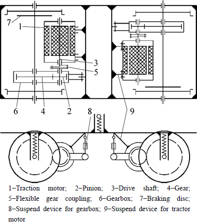
Fig. 1 Schematic of frame-mounted driving system [1]:
The objective of the present work is to investigate super-harmonic dynamics of the gear transmission system in the high-speed train with consideration on the stick-slip vibration of the system. The organization of this paper is as follows. It starts with a parametric vibration model of the gear transmission system with the time-varying mesh stiffness, the transmission error and the tooth backlash in Section 2. The load torque of the gear transmission system under the state of the stick-slip vibration is also incorporated. In Section 3, the super-harmonic responses and the stabilities of the gear transmission system under the state of the stick-slip vibration are analyzed in detail. A summary of the current work is given finally.
2 Model of gear transmission system
With neglecting the elastic effect, the gear transmission system in the high speed can be simplified to a torsional vibration model with two degrees of freedom (DOFs) (see Fig. 2), whose equations of motion can be written as [14]
 (1)
(1)
where ��p and ��g are the angular displacements of the pinion and the gear wheel, respectively; Ip and Ig are the moments of inertia of the pinion and the gear wheel, respectively; Rp and Rg are the pitch circular radiuses of the pinion and the gear wheel, respectively; i is the transmission ratio; e(t) is the static transmission error function; km is the time-varying meshing stiffness of the system; cm is the damping of the meshing; Tp is the driving torque of the system; Tg is the driven torque of the system.

Fig. 2 Reduced dynamic model of gear transmission system
Introducing the dynamic transmission error
 (2)
(2)
then, substituting Eq. (2) into Eq. (1), one has
 (3)
(3)
where me is the equivalent inertia mass of the gear pair and is defined by

The first term in the right of Eq. (3), composed of fm and (Tg�CTg0), represents a generalized applied force of the system, where (Tg�CTg0) is the dynamic torque of the gear systems and fm is expressed by

Other variables and parameters in Eq. (3) are discussed below.
2.1 Gear backlash f(x)
Gear backlash, a clearance between mating gear teeth, is built into speed reducers to let the gears mesh without binding and to provide space for a film of lubricating oil between the teeth. It prevents overheating and tooth damage. In the analysis, the effect of the gear backlash can be treated with a piecewise linear function f(x), which is expressed as
 (4)
(4)
where b is the width of the backlash. For simplicity, a polynomial of three-order is used to approximate the gear backlash function f(x) in this paper. The used polynomial is f(x)=a1x+a3x3, in which a1=0.167, a3=0.064. Comparisons of the results for the gear backlash obtained from the above two methods are depicted in Fig. 3.

Fig. 3 Gear backlash curves
2.2 Mesh stiffness km
Various methods for determining the mesh stiffness exist. An accurate estimation of the meshing stiffness can be found in Ref. [15]. In Ref. [15], seven different stiffness functions are addressed. During the meshing process, the mesh stiffness can vary in a periodical manner. Thanks to it, a popular method is to expand the meshing stiffness km as a function of the meshing frequency using the Fourier series, which has the form of:
 (5)
(5)
where Ks is the average mesh stiffness, which is related to the maximum stiffness kmax of one pair of the teeth. The maximum stiffness kmax usually owes to a design level. For some details, one can refer to Ref. [15]. Kj is the fluctuation in amplitude; fj is the phase angle; is the meshing circular frequency and is defined by
  in which n1 and n2 are respectively the angular velocities of the pinion and the gear wheel, Z1 and Z2 are respectively the number of teeth of the pinion and the gear wheel.
Unlike the above method, the mesh stiffness km is calculated here using the finite element method. As well known, the mesh stiffness can be straightforwardly defined as the ratio of the applied load to its response, e.g., the required force that can generate 1 ��m deformation on 1 mm face width while a pair of the teeth or several pairs of the teeth are engaged. Let n be the number of teeth and the deformations of the pinion and the gear teeth are ��pi with i=1, ��, n and ��gi, respectively. Hence, the mesh stiffness can be alternatively given as
 (6)
(6)
where n is the number of the teeth; Fti are the meshing contact forces; ��pi are the deformations of the pinion; ��gi are the deformations of the gear teeth.
To demonstrate the calculation of the mesh stiffness, a helical gear drive is considered here. Geometric parameters of the considered gear drive are listed in Table 1. Figure 4 shows the finite element model of the considered gear drive. It includes 86750 nodes and 68460 elements (C3D8I element in ABAQUS). In simulation, the boundary conditions are described below. A fixed displacement constraint is applied on the boundary surface of the gear and a radial constraint is exerted on the boundary surface of the pinion. The pinion subjects to the distributed forces, which can be obtained according to the torque. Once the deformations of the pinion and the gear are obtained, the mesh stiffness can be calculated using Eq. (6). The corresponding results are plotted in Fig. 5 by the solid line. To validate the above-obtained results, the mesh stiffness also calculated using Eq. (5) and the results are represented by a dotted line in Fig. 5. From Fig. 5, one can see that the results obtained from the two methods match well.
2.3 Gear errors e(t)
The effect of gear errors on the dynamic load and on the dynamic transmission error was extensively discussed by many researchers [16]. The gear error is caused by the deviation of the gear tooth profile surface from the ideal surface and it can be defined as the difference between the actual position of meshing and the theoretical position of meshing on the meshing line position,consequently. Four different types of gear errors are usually considered, namely tooth profile, normal pitch, pressure angle and run-out errors. Of the four errors, the gear tooth profile error is common and important in the gear system. In many cases, it can be considered to be periodic function as Eq. (7), which is shown in Fig. 6.
 (7)
(7)
where er is the constant amplitude of gear meshing errors; Tz is the gear meshing cycle; fh is the phase angle.
Table 1 Gear parameters used in simulation


Fig. 4 Contacting finite element model of gear pair
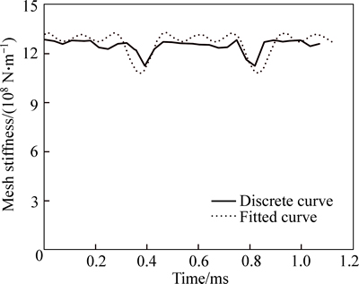
Fig. 5 Time history of mesh stiffness
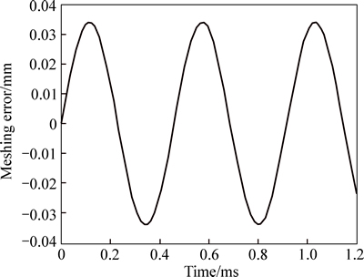
Fig. 6 Meshing error curve
2.4 Torque under stick-slip vibration
When the train is at a normal state, the load torque between the wheel and the rail is stable, and has less effect on the gear transmission system. However, the torque can largely fluctuate as the train enters into the driving or braking process, where the train can have large sliding vibrations. To address these problems in the analysis, the wheel-rail tangential force is considered, consequently. The wheel-rail tangential force largely associates with a dynamic coefficient ��. This coefficient is inversely related to the slip after the peak of adhesion and has a piecewise linear property against the slip rate (see Fig. 7). Figure 7 depicts a simplified wheel-rail adhesion curve according to the experimental result [17].

Fig. 7 Tangential force coefficient curve
In Fig. 7, the slip rate, s, describing the slippage can be defined by
 (8)
(8)
where V is the instantaneous speed of the wheel-set; v0 is the mean speed of the wheel-set; �� is the instantaneous angular velocity of the wheel-set; r0 is the radius of the wheel; is the longitudinal velocity rate of the wheel-set; ��0 is the mean angular velocity of the wheel-set. Considering =0, r��=0,
  =0, one has the average slip rate:
 (9)
(9)
The dynamic coefficient for the wheel-rail tangential force is therefore calculated as
 (10)
(10)
where ��m is the maximum tangential force coefficient; sm is the critical slip rate; k�� is the negative slope on the sliding. If the slip rate is smaller than the critical slip rate, the system exhibits the stick vibration. Otherwise, the system is observed under the slip vibration.
The moment between the wheel and the rail can be expressed as
 (11)
(11)
where W0 is the axle load of wheel-set; Tg consists of the static moment Tg0 and the dynamic moment T ��.
Substituting Eq. (10) into Eq. (11) yields
 (12)
(12)
Similarly, the substitution of Eq. (9) into Eq. (11) leads to
 (13)
(13)
Considering Eqs. (12) and (13), one obtains the dynamic moment T�� that accounts for the system under a special state between the stick and slip process. The dynamic moment of the system on the stick state is:
 (14)
(14)
The dynamic moment of the system at the slip state is:
 (15)
(15)
Without loss of generality, let  . So,
. So,  in Eq. (15) can be expanded in Taylor��s series as
 (16)
(16)
After neglecting the second and higher order terms, the dynamic moment of the system at the slip state is
 (17)
(17)
Similarly, one can have the dynamic moment of the system at the stick state.
Substituting Eq. (17) into Eq. (3) leads to
 (18)
(18)
where c1 and F1 are the equivalent damping and dynamic load caused by the stick-slip vibration, respectively, taking slip state for example, the equivalent damp and dynamic load can be written as
 (19)
(19)
 (20)
(20)
Similarly, one can obtain the equivalent damp and dynamic load of the system at the stick state.
3 Super-harmonic resonance
Introducing the following the variables: x=bu, 


 the dimensionless equation of motion for Eq. (18) can be written as

 (21)
(21)
Considering a small parameter �� and using the multiple scales method [18], Eq. (21) can be rewritten to
 (22)
(22)
An approximate solution of Eq. (22) can be expressed in the following form:
 (23)
(23)
where T0=�� is a fast scale and T1=�Ŧ� is a slow time scale.
Substituting Eq. (23) into Eq. (22), and separating the equation terms based on the orders of ��, one has
 (24)
(24)

 (25)
(25)
where D0 and D1 are the derivatives of the variable with respect to the time scales T0 and T1, respectively. The solution of Eq. (24) can be expressed as

 (26)
(26)
where an over line denotes the conjugate transpose and 
Substituting Eq. (26) into Eq. (25), one has


 (27)
(27)
where cc denotes the complex conjugate of the preceding terms. Note that the expression  in Eq. (27) is the secular term. It should be eliminated from the steady- state solution of Eq. (27). Similarly, when the excitation frequency ��e has the following relationships:


 one should remove other secular terms form the solution.
Generally, the gear transmission system of high- speed train often exhibits a super-harmonic resonance since it has a high natural frequency. In this work, the super-harmonic resonance of the gear transmission system is investigated. For this purpose, a detuning parameter �� is introduced here to express the closeness of the excitation frequency ��e to the primary frequency ��1 of the system, which satisfies with
 (28)
(28)
Inserting Eq. (28) into Eq. (27), then eliminating all secular terms in Eq. (27), one obtains

 (29)
(29)
Let  where �� and �� are the real functions. Using the expression of A in Eq. (29) and separating real and imaginary parts, the amplitude- frequency characteristic equations are obtained:
 (30)
(30)
 (31)
(31)
where the variable 
The steady-state solution of Eqs. (30) and (31) corresponds to the conditions  Considering these conditions and eliminating sin �� and cos �� from Eqs. (30) and (31), one obtains
 (32)
(32)
It is interesting to note from Eq. (32) that the super- harmonic amplitude of the gear system depends on not only its dynamic load, damping and backlash, but also the equivalent damp and load caused by the stick-slip vibration. The effects of damping coefficients �� and the dynamic load f1 on the steady state amplitude are analytically discussed below. Results are shown in Figs. 8 and 9. Figure 8 shows the frequency-response curves for the different force f1 when the gear transmission system is under the stick state (f1=0.1), slip state (f1=0.5) and without stick-slip vibration (f1=0.3), respectively. The multi-valued region of the solution of the system and a jump phenomenon are observed in Fig. 8. Moreover, one can see that the frequency- response curve bends to the right, which indicates the system has a hard spring effect. Of great surprise and interest, the force f1 under different states has no significant effects on the amplitude of the response of the system at the steady state. But, the resonance frequency varies against with the force f1. It implies that the measurement of the resonance frequency of the wheel- sets can be regarded as a potential way to identify the slippage of the wheel-rail. The effect of the damping coefficient �� on the steady-state response of the system is illustrated in Fig. 9. In this analysis, the vibration of the system with the stick state (��=0.2), the vibration of the system with the slip state (��=0.1) and the vibration of the system without the stick-slip state (��=0.15) are examined. Similarly, the multi-valued solutions and the jump phenomenon in the steady-state response of the system are found. It is also noted in Fig. 9 that the maximum amplitude of the steady-state response of the system is monotonically decreased against with the damping coefficient ��. A smaller damping coefficient �� of the gear transmission system under the slip state can induce a larger amplitude of the system steady-state response. On the contrary, the system has a larger damping and a smaller response under the stick state.

Fig. 8 Comparison of amplitude-frequency curves for different f1

Fig. 9 Comparison of amplitude-frequency curves for different ��
4 Stability analysis
To analyze the stability of the fixed points of Eqs. (30) and (31), we apply Lyapunov��s first method in the form:
 (33)
(33)
where u and v are the real functions. Substituting Eq.(33) into Eqs. (30) and (31), and equating the real and imaginary parts of the resulting equations, one has
 (34)
(34)
 (35)
(35)
Equations (34) and (35) are expressed by a set of autonomous ordinary differential equations of the first order. The stability of a particular fixed point of Eqs. (34) and (35) is therefore determined by the eigenvalues of the Jacobian matrix of the right hand sides of the equations. The corresponding eigen equation is
 (36)
(36)
The eigenvalues solved from Eq. (36) are
 (37)
(37)
In this research, since the discriminant of Eq. (36) is less than zero, the eigenvalues are a pair of conjugate complex roots. When the coefficient ��<0, the real parts of the eigenvalues are positive, singular points are unstable foci based on the perturbation theory. When the coefficient ��>0, the real parts of the eigenvalues are negative, singular points are stable foci. When coefficient ��=0, the eigenvalues are a pair of pure imaginary zeros. In this case, singular points are centers. In the present paper, the damping �� is the synthetic damping which takes into account both meshing damping and equivalent damping caused by the slip vibration, and the synthetic damping of the gear system may be zero when the wheel-set has a large sliding. In this case, ��=0 and ��e��0, Eq. (36) has a pair of pure imaginary roots with zero real parts. According to the nonlinear bifurcation theorem, the Hopf bifurcation occurs. So, it can be conclude that stick-slip vibration may cause the Hopf bifurcation of gear transmission system.
5 Numerical simulations
In this section, numerical simulation for the gear transmission system of a high-speed train is carried out. The parameters of the gear pair are given in Table 1, and the parameters describing the stick-slip vibration of the system are as follows: ��m=0.25, sm =0.03, k��=-0.25, the average slip rates s0 for the stick state and slip state are 0.01 and 0.06, respectively. The dynamic responses of the gear transmission system are analyzed as the train under the stick state, the slip state and the state without the stick-slip vibration. Figures 10(a), (b) and (c) depicting the steady-state responses of the gear system are plotted based on the results obtained from numerically solving Eq. (21) using MATLAB, and Figs. 11(a) and (b) present the frequency spectrum of the steady-state responses of the gear system under the stick state and slip state. It is clearly observed from the time histories of the responses of the system that the force f1 under different states has little effects on the vibration amplitudes and it just changes the position of the equilibrium point, which validates the results obtained by the analytic solution in the last section.
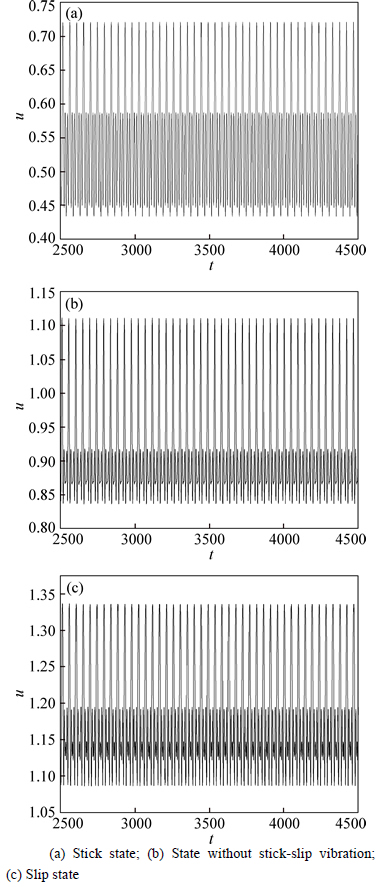
Fig. 10 Time history of response of gear system at different states:

Fig. 11 FFT spectrum of response of gear system at different states:
Figures 12(a), (b) and (c) show the phase trajectories of the gear transmission system when the train is under the stick state, the slip state and the state without the stick-slip vibration. Because of the time- varying mesh stiffness, the internal dynamic excitation always exists in the gear transmission system. It is noted that the gear transmission system has the stable periodic movements even without the stick-slip vibration. During the stick state, the movement of the gear transmission system is also periodic, whose amplitude is much smaller than that of the response of the system under the state without the stick-slip vibration. It means that it has the role of offering damping to the gear system under the stick vibration, and the synthetic damping of the gear system becomes larger. While the system exhibits the slip vibration, its movement is no longer stable periodic. In this case, the system becomes unstable. According to the above stability analysis, one can conclude that the synthetic damping of the gear system is less than zero and a critical dynamic phenomenon known as the Hopf bifurcation appears with the violent vibration of the system. Due to the violent vibration of the gear system, the process of train operation should be carefully investigated.

Fig. 12 Phase diagrams of system at different states:
6 Conclusions
1) The time-varying stiffness of the meshing teeth pairs is the main cause of harmonic vibrations of the gear transmission system. The self-excited excitation of the wheel-set is caused by the negative gradient of adhesion effect which changes with the wheel-rail creep velocity.
2) In analysis, the synthetic damping of the gear system composed of the meshing damping and the equivalent damping caused by the stick-slip vibration should be considered. The equivalent damping and loads can vary when the system is under the state with the stick-slip vibration.
3) The system has complex nonlinear phenomena such as multi-valued solutions, jump phenomenon. The loads of the system under the different states have little effects on the steady-state amplitudes of the system response. The change of the system load can influence the resonance frequency of the system at the steady state. Synthetic damping of the gear system can be less than zero when the system possesses the stick-slip vibrations. In this case, a critical dynamic phenomenon known as the Hopf bifurcation arises with the violent vibration response of the system. Much special attentions should be paid to the starting process of the train operation.
References
[1] ZHANG Wei-hua, SHEN Zhi-yun, ZENG Jing. Study on dynamics of coupled systems in high-speed trains [J]. Vehicle System Dynamics, 2013, 51(7): 966-1016.
[2] WANG Jian-de, HOWARD I. Finite element analysis of high contact ratio spur gears in mesh [J]. Journal of Tribology, 2005, 127(7): 469-483.
[3] LI Tong-jie, ZHU Ru-peng, BAO He-yun, XIANG Chang-le. Stability of motion state and bifurcation properties of planetary gear train [J]. JournalofCentralSouthUniversity, 2012, 19: 1543- 1547.
[4] KAHRAMAN A, SINGH R. Interactions between time-varying mesh stiffness and clearance non linearities in a geared systems [J]. ASME Journal of Sound and Vibration, 1991, 146(1): 135-156.
[5] KAHRAMAN A. Effect of axial vibrations on the dynamics of a helical gear pair [J]. ASME Journal of Sound and Vibration, 1993, 115(1): 33-39.
[6] BENTON M, SEIREG A. Factors influencing instability and resonance in geared systems [J]. Journal of Mechanical design, 1981, 103: 372-378.
[7] BLANKENSHIP G W, KAHRAMAN A. Steady state forced response of a mechanical oscillator with combined parametric excitation and clearance type nonlinearity [J]. ASME Journal of Sound and Vibration, 1995, 185(5): 743-765.
[8] BLANKENSHIP G W, SINGH R. A new gear mesh interface dynamics model to predict multi-dimensional force coupling and excitation [J]. Mechanism and Machine Theory, 1995, 30(1): 43-57.
[9] BLANKENSHIP G W, SINGH R. Dynamic force transmissibility in helical gear pairs [J]. Mechanism and Machine Theory, 1995, 30(3): 323-339.
[10] POLACH O. A fast non-steady creep force model based on the simplified theory [J]. Vehicle System Dynamics Supplement, 1999, 33: 728-739.
[11] POLACH O. Influence of locomotive tractive effort on the forces between wheel and rail [J]. Vehicle System Dynamics Supplement, 2001, 35: 7-22.
[12] YAO Yuan, ZHANG Hong-jun, LI Ye-ming. The dynamic study of locomotives under saturated adhesion [J]. Vehicle System Dynamics. 2011, 49(8): 1321�C1338.
[13] YAO Yuan, ZHANG Hong-jun, LUO Shi-hui. An analysis of resonance effects in locomotive drive systems experiencing wheel/rail saturation adhesion [J]. Proceedings of the Institution of Mechanical Engineers, Part F: Journal of Rail and Rapid Transit, 2014, 228(1): 4-15.
[14] LI Run-fang, WANG Jian-jun. Gear system dynamics [M]. Beijing: Science Press, 1997. (in Chinese)
[15] UMEZAWA K, SATO T, ISHIKAWA J. Simulation on rotational vibration of spur gears [J]. Bulletin of the Japan Society of Mechanical Engineers. 1984, 27: 102-109.
[16] AMABILI M, RIVOLA A. Dynamic analysis of spur gear pairs: Steady-state response and stability of the SDOF model with time-varying meshing damping [J]. Mechanical Systems and Signal Processing, 1997, 11(3): 375-390.
[17] ZHANG Wei-hua, CHEN Jian-zheng, WU Xue-jie. Wheel/rail adhesion and analysis by using full scale roller rig [J]. Wear, 2002, 253: 82-88.
[18] EISSA M, KAMEI M, BAUOMY H S. Dynamics of an AMB-rotor with time varying stiffness and mixed excitations [J]. Meccanica, 2012, 47: 585-601
(Edited by YANG Hua)
Cite this article as: HUANG Guan-hua, XU Si-si, ZHANG Wei-hua, YANG Cai-ji. Super-harmonic resonance of gear transmission system under stick-slip vibration in high-speed train [J]. Journal of Central South University, 2017, 24(3): 726-735. DOI: 10.1007/s11771-017-3474-0.
Foundation item: Project(U1234208) supported by the National Natural Science Foundation of China; Project(2016YFB1200401) supported by the National Key Research and Development Program of China
Received date: 2015-02-09; Accepted date: 2016-12-01
Corresponding author: XU Si-si, Engineer; Tel: +86-18001270166; E-mail: napsisi@163.com
