Thermal elastohydrodynamic lubrication of modified gear system considering vibration
来源期刊:中南大学学报(英文版)2020年第11期
论文作者:王优强 菅光霄 张平 李云凯 罗恒
文章页码:3350 - 3363
Key words:involute spur gear; tribo-dynamics model; oil film stiffness; modification coefficient; lubrication property
Abstract: The thermal elastohydrodynamic lubrication characteristics of a modified gear system under a dynamic load were investigated, including the influence of the modification coefficient and vibrations. Based on the dynamic theory of gear systems, a six-degree-of-freedom tribo-dynamics model was established. Thermal elastohydrodynamic lubrication characteristics of a modified gear system under vibrations and a static load were analyzed. The results showed that the positive transmission gear system exhibited the better lubrication effect compared with other transmission types. A thick lubricating oil film could be formed, and the friction coefficient between the teeth and the oil film flash temperature were the smallest. As the modification coefficient increased, the lubrication condition was continuously improved, and the scuffing load capacity was enhanced. The increment of the modification coefficient increased the meshing stiffness of the gear system but reduced the stiffness of the oil film.
Cite this article as: JIAN Guang-xiao, WANG You-qiang, ZHANG Ping, LI Yun-kai, LUO Heng. Thermal elastohydrodynamic lubrication of modified gear system considering vibration [J]. Journal of Central South University, 2020, 27(11): 3350-3363. DOI: https://doi.org/10.1007/s11771-020-4551-3.

J. Cent. South Univ. (2020) 27: 3350-3363
DOI: https://doi.org/10.1007/s11771-020-4551-3

JIAN Guang-xiao(菅光霄)1, WANG You-qiang(王优强)1, ZHANG Ping(张平)2,LI Yun-kai(李云凯)1, LUO Heng(罗恒)1
1. School of Mechanical and Automotive Engineering, Qingdao University of Technology,Qingdao 266520, China;
2. School of Mechanical Engineering, East China University of Science and Technology,Shanghai 200237, China
 Central South University Press and Springer-Verlag GmbH Germany, part of Springer Nature 2020
Abstract: The thermal elastohydrodynamic lubrication characteristics of a modified gear system under a dynamic load were investigated, including the influence of the modification coefficient and vibrations. Based on the dynamic theory of gear systems, a six-degree-of-freedom tribo-dynamics model was established. Thermal elastohydrodynamic lubrication characteristics of a modified gear system under vibrations and a static load were analyzed. The results showed that the positive transmission gear system exhibited the better lubrication effect compared with other transmission types. A thick lubricating oil film could be formed, and the friction coefficient between the teeth and the oil film flash temperature were the smallest. As the modification coefficient increased, the lubrication condition was continuously improved, and the scuffing load capacity was enhanced. The increment of the modification coefficient increased the meshing stiffness of the gear system but reduced the stiffness of the oil film.
Key words: involute spur gear; tribo-dynamics model; oil film stiffness; modification coefficient; lubrication property
Cite this article as: JIAN Guang-xiao, WANG You-qiang, ZHANG Ping, LI Yun-kai, LUO Heng. Thermal elastohydrodynamic lubrication of modified gear system considering vibration [J]. Journal of Central South University, 2020, 27(11): 3350-3363. DOI: https://doi.org/10.1007/s11771-020-4551-3.
1 Introduction
Aviation transmission gears are subjected to high carrying capacities and harsh operating conditions, and the reliability requirements are high. For non-linear gear systems, especially high-speed heavy-duty gear systems, the influence of dynamic loads induced by vibrations on the lubrication characteristics cannot be ignored. Some studies [1-5] had suggested that inertial forces and damping ratio are two significant factors for the transmission characteristics. At present, research of gear transient lubrication is mostly carried out by simplified static load models [6-9]. Some scholars have also considered the effects of dynamic loads induced by vibrations or impacts on lubrication. GLOVNEA et al [10] calculated the oil film thickness under the harmonic loading. LU et al [11] and LIU et al [12] analyzed the lubrication performance of involute spur gears based on dynamic load model and obtained the numerical solution of oil film pressure and friction coefficient along the line of action (LOA). WANG et al [13, 14] investigated the effect of damping ratio and velocity, and obtained numerical solutions for dynamic loads accounting for the oil film thickness and temperature rise. SHI et al [15] considered the effect of time-varying entrainment velocity on lubrication performance based on one thermal-mixed lubrication model, but ignored the influence of dynamic loading induced by variable velocity. YANG [16] carried out one research on thermo-elastic coupling and vibration damping with modification of helical gear system and ZHANG [17] studied lubrication and dynamics contact performance of double involute gear. WANG et al [18-20] analyzed the effect of impact loading on lubrication, but ignored the fluctuation of velocity. de la CRUZ et al [21] established a tribo-dynamics model for spur gears and conducted useful studies of the transient thermal mixed lubrication. The results showed that the oscillation of the oil film pressure and thickness aggravated the vibrations of the gear system and contributed to the production of noise. XUE et al [22] and JIAN et al [23] analyzed the dynamic loading of involute spur gears based on the time-varying meshing stiffness using numerical simulations. LI et al [24, 25] investigated the fatigue characteristics of involute spur gears based on one tribo-dynamics model. BARBIERI et al [26] established one coupled model for gear lubrication and vibration and the results showed that the oil film pressure and thickness were influenced by the dynamic loading. Although the above studies considered the effect of dynamic loads, the influence of the velocity fluctuations on the teeth surfaces caused by the impact load or vibrations were neglected. MA [27] studied the quasi-static and dynamic behavior of double helical gears. In addition, some scholars [28-31] studied the oil film stiffness based on a static load model but did not relate them to vibrations. ZOU et al [32, 33] carried out coupling research on elasto- hydrodynamic lubrication (EHL) and vibration, but the description of the dynamic properties exhibited by the oil film under the dynamic load was insufficient. LIU et al [34, 35] analyzed the dynamic behaviors of helical and spur gears based on the elasto-hydrodynamic lubrication theory and a non-linear dynamic model, and demonstrated the influence of constant and variable excitations. YUAN et al [36-38] studied the lubrication characteristics based on one mixed lubrication model considering the coupling effect of the lubrication and vibrations. The results were significant for subsequent studies.
At present, few studies have focused on the dynamic and lubrication characteristics of modified gear systems. In this paper, a six-degree-of-freedom tribo-dynamics model of a gear system is first established. Based on the numerical solution for the lubrication, a model of the oil film stiffness was also established. Analysis of the vibration and lubrication coupling of the gear system was carried out based on different transmission types and modification coefficients.
2 Modelling
2.1 Geometric model
Figure 1 shows the transmission model of an involute spur gear system, reflecting the meshing state of a pair of teeth at point K. N1 and N2 represent the theoretical engage-in and recess point, respectively. A is the true engage-in point and D is the true recess point. During one complete cycle for the gear transmission, represents the actual length of LOA. From points A to B, there are two pairs of meshing teeth. Points B and C represent the starting and final points of the zone that only has one pair of meshing teeth, respectively. From points C to D, there are two pairs of meshing teeth. Point P is the pitch point. rbp and rbg denote the radii of the base circles of the gears (p represents the pinion gear and g denotes the driven gear), and their angular velocities are denoted as ωp and ωg, respectively.
2.2 Six-degree-of-freedom tribo-dynamics model
For high-speed and heavy-duty gear systems,the inertial force and damping have significant effects on the transmission characteristics, and thus, dynamic analysis is necessary. Considering the effect of friction, a dynamic model of the gear system is established, as shown in Figure 2.
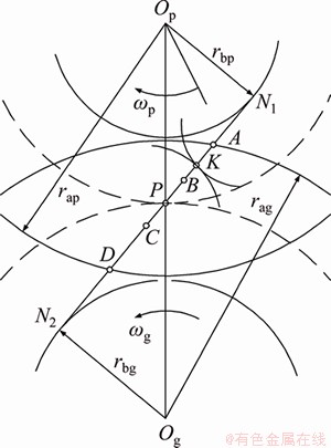
Figure 1 Model of gear transmission
The model takes the torsional and translational vibrations of spur gears into consideration. As shown in Figure 2, the y-axis is in the direction of the LOA The torsional angular displacements of the pinion and driven gears are denoted as θp and θg, respectively. Ip represents the moment of inertia of the pinion gear, and Ig represents the moment of inertia of the driven gear. The meshing stiffness and damping are denoted as kt and ct, respectively. The static transmission error is et.
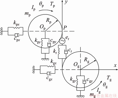
Figure 2 Dynamic model of gear system
For a standard gear transmission, at the meshing point K, the linear velocity of the pinion and driven gears should be equal. However, due to manufacturing errors, geometric errors of the gear, and the variation of the stiffness, load, and temperature during the transmission process, the linear velocity of the driven gear often lags behind that of the pinion gear. Thus, there is a transmission error. The manufacturing and geometric errors of gears are the source of static transmission errors, whereas variations of the meshing stiffness, load, and temperature cause dynamic transmission errors. In this paper, the manufacturing and geometric errors were neglected, and thus, the static transmission error is considered to be zero.
For the gear system, the dynamic transmission error of the gear system is:
 (1)
(1)
where yp and yg denote the vibration displacements of the pinion and driven gears along the LOA at point K, respectively.
The dynamic load between the pinion and driven gears is as follows:
 (2)
(2)
The dynamic friction in the x direction can be written as:
 (3)
(3)
where f is the friction coefficient and λi denotes the direction coefficient of friction. The friction is in the positive direction of the x axis if λi>0, where
 (4)
(4)
Based on the dynamic model of the gear system, the differential equation is established as [39]:
 (5)
(5)
where xp(t) and xg(t) represent the displacement of the pinion gear and driven gear caused by vibration along the x direction, respectively.
The Weber method [40] was used to determine the time-varying meshing stiffness of the gear system. The fourth-order Runge-Kutta method was applied to solve the differential equations, and dynamic characteristics, such as the dynamic load and fluctuating velocity during the gear transmission process, were calculated.
2.3 Model of lubrication
2.3.1 Basic contact parameters of gear system
As shown in Figure 2, according to the properties of involute curves, the radii of curvature at any possible meshing point K can be denoted as follows:
 (6)
(6)
where s denotes the distance from the meshing point K to the pitch point P; φ represents the working pressure angle.
The value of φ can be obtained by the following equation:
 (7)
(7)
where z1 and z2 denote the tooth number of the pinion gear and driven gear, respectively; and the corresponding modification coefficients are denoted as x1 and x2.
The comprehensive radius of curvature at any possible meshing point K is:
 (8)
(8)
The torsional and translational vibrations existing in the transmission process will inevitably cause the entrainment velocity to fluctuate.
The entrainment velocity can be denoted as follows:
 (9)
(9)
 (10)
(10)
where u represents the fluctuating component of the entrainment velocity.
2.3.2 Governing equations for lubrication
The generalized Reynolds equation can be obtained by [39]:
 (11)
(11)
where p is the oil film pressure, Pa; h is the oil film thickness, m; η and ρ denote the viscosity, Pa・s, and density of the lubricant, kg/m3, respectively.
The oil film pressure must satisfy the following equation:
 (12)
(12)
where, when considering vibrations, w is the dynamic loading, N/m, obtained by Eq. (2), i.e., w=Fp.
The energy equation [40] applied to lubricant can be written as follows:

 (13)
(13)
where c is the constant-pressure-specific heat capacity of the lubricant; k is the thermal conductivity coefficient; the flowing velocity of lubricant is written as u*.
The thermal conduction equation applied to the pinion gear and driven gear can be written as:
 (14)
(14)
where kp and kg denote the thermal conductivity coefficient of the pinion gear and driven gear, respectively; the specific heat capacity of the pinion gear and the driven gear can be written as cp and cg, respectively; zp and zg represent the dimensions of the pinion gear and driven gear in the z direction, respectively.
Other governing equations for lubrication, such as the equation of the oil film thickness, the viscosity-pressure equation, and density-pressure equation, can be found in Ref. [41].
2.3.3 Calculating oil film stiffness
The value of the oil film stiffness can be obtained by the following equation:
 (15)
(15)
where hc is the center oil film thickness.
The oil film stiffness and the meshing stiffness of gear system are both time-varying. Therefore, in order to explore the coupling effect of vibration and lubrication, the oil film stiffness can be coupled with the meshing stiffness to obtain the comprehensive stiffness of the system. The formula can be denoted as follows:
 (16)
(16)
where kh and km represent the oil film stiffness and the meshing stiffness, separately; and k denotes the comprehensive stiffness after coupling.
3 Numerical method
The governing equations of lubrication described above was solved using the Gauss-Seidel iteration method and their boundary conditions can be found in Ref. [6]. The Reynolds equation was solved using a uniform grid based on the finite difference method. The solution of oil film pressure was obtained by the multigrid technique. The column scanning technique was utilized to calculate oil film and surface temperature. One W-cycle was utilized in the multigrid method, and the steps involved in to obtain converged solutions can be found in Ref. [42]. The solution of elastic deformation was obtained by the multi-level multi-integration method [42]. In order to calculate oil film pressure and thickness, six levels of grids were used in the multigrid method and multi-level multi-integration method. Along the x direction, there were 961 nodes on the finest level and the real calculation domain for the infinite line contact was between Xin=-4.6 and Xout=1.4.
Along the line of action, the transient Reynolds equation was solved in 180 time steps. Based on the multi-grid method, the pressure must be relaxed on each grid level and the convergent criterions for pressure and load can be defined as follows:

ERRW≤0.001 (17)
where the relaxation solution obtained after v0 and v1 relaxation iterations was denoted as  and
and is the initial iteration value.
The calculation process for studying the vibration and lubrication coupling is shown in Figure 3. As shown in Figure 3, the relative error for the vibration displacement and vibration velocity were written as ERRδ and ERRu, respectively. ERRkh represented the relative error for the oil film stiffness. These convergence criterions were defined as follows:


 (18)
(18)
4 Results and discussion
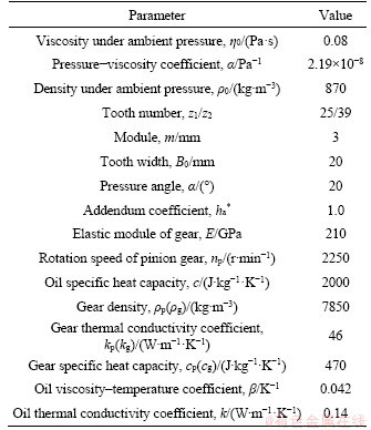
The basic parameters for the gear transmission and lubrication are shown in Table 1.
4.1 Effects of different transmission types on lubrication
The lubrication performances of different transmission types were analyzed based on the simplified static load model. The different transmission types were defined as follows:
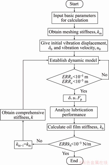
Figure 3 Flowchart for studying vibration and lubrication coupling
Table 1 Basic parameters for calculation
Positive drive: 
Negative drive: 
Equivariant drive:

Standard drive: 

Figure 4 shows the comparison of the lubrication characteristics when different transmission types were adopted. S reflects the distance between the meshing and pitch points when the meshing point changes along the LOA. S=0 denotes the position of the pitch point. The range of S reflects the length of the LOA and represents the value of the contact ratio for the different transmission types.
Figure 4(a) shows the distribution of the load along the LOA. In Zone I, there were two pairs of meshing teeth. However, in Zone II, there was only one pair of teeth meshing.
As shown in Figure 4(b), in Zone II, the friction coefficients of the negative drive, equivariant drive, and standard drive were greater than 0.1, which indicates that the two gear teeth in contact with each other were under boundary lubrication conditions. For the positive drive, the friction coefficient was less than 0.1, which indicates that the two gear teeth in contact with each other were under full-film lubrication conditions. The results show that positive drive could improve the lubrication condition of the gear system, whereas the negative drive worsened the lubrication condition. In most areas of the gear meshing, the friction coefficient of the positive drive was the smallest among the different transmission types. This was because, compared with the other three transmission types, as shown in Figure 4(d), the oil film thickness of the positive drive was the largest.
Figure 4(c) shows the variation of the oil film flash temperature in dimensionless form and the slide-roll ratio along the LOA. Among different transmission types, the flash temperature of the positive drive was the smallest, whereas that of negative drive was the largest in most areas of transmission. This was mainly because the positive drive had the smallest slide-roll ratio. The results were consistent with the research of LUO [43]. Based on a finite element simulation, LUO [43] considered the temperature distribution of the gear body to be related to the average heat flux. The average heat flux was affected by the half width of the Hertz contact zone, relative sliding velocity, and the maximum contact stress. Among the different transmission types, the average heat flux of the positive drive was the smallest, and the flash temperature was the lowest. The average heat flux of the negative drive was the highest, and the flash temperature was the highest.
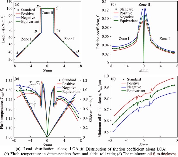
Figure 4 Lubrication characteristics under different transmission types:
As shown in Figures 4(b)-(d), among the different transmission types, the friction coefficient and flash temperature of the positive drive were the smallest, whereas the oil film thickness was the largest. However, the friction coefficient and flash temperature of the negative drive were the largest, whereas the oil film thickness was the smallest. The flash temperature and oil film thickness are two important indictors to evaluate the scuffing load capacity of the gear system. An oil film that is too thin cannot separate the tooth surfaces adequately and causes scuffing failure. From the above analysis, it was concluded that the positive drive could enhance the scuffing load capacity and improve the lubrication condition of the gear system.
Figure 5 shows the effects of different transmission types on the lubrication in terms of the mechanism. The modification coefficient had a significant influence on the tooth profile. A positive modification coefficient enlarged the tooth profile, whereas a negative modification coefficient caused it to thin. Consequently, among the different transmission types, both the comprehensive radius of curvature and the entrainment velocity were the largest when the positive drive was adopted. However, for the negative drive, the comprehensive radius of curvature was the smallest, causing the entrainment velocity to be the smallest inevitably. The entrainment velocity mainly influenced the oil film thickness. As shown in Figures 4(d) and (b), when the positive drive was adopted, the oil film thickness was the largest, whereas the friction coefficient was the smallest compared with the other three transmission types.
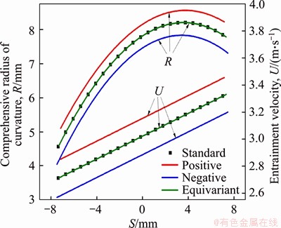
Figure 5 Distribution of comprehensive radius of curvature and entrainment velocity along LOA
4.2 Effects of different modification coefficients on lubrication
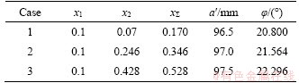
According to the above analyses for different transmission types, the positive drive exhibited the best lubricating performance. The analyses were based on a simplified static load model. Thus, in this section, based on a tribo-dynamics model, vibration and lubrication coupling was studied for different modification coefficients when the positive drive was adopted. Basic parameters for the calculation are shown in Table 2. The sum of the modification coefficients (x1 and x2) is denoted as xΣ, and a′ represents the actual center distance between the pinion and driven gears. The working pressure angle is denoted as φ.
Table 2 Basic parameters for calculation
4.2.1 Analysis of dynamic characteristics
Figure 6(a) illustrates the distribution of the oil film stiffness along the LOA. The oil film stiffness decreased with an increase in the modification coefficient. As shown in Figure 5, increasing the sum of the modification coefficients led to an increase in the entrainment velocity, and the oil film thickness increased. A thicker oil film corresponded to an increase in the distance between lubricant molecules as well as a decrease in the intermolecular repulsion. The smaller the intermolecular repulsion between the lubricant molecules was, the more easily the oil film was compressed, which means that the oil film stiffness was smaller.
Since the meshing stiffness of the gear system and oil film stiffness are time varying, the comprehensive stiffness of the gear system can be obtained by coupling them. The meshing stiffness and comprehensive stiffness are shown in Figure 6(b). The meshing stiffness and comprehensive stiffness increased with the increase in the sum of the modification coefficients. When the sum of the modification coefficients was fixed, the comprehensive stiffness obtained after the coupling was slightly smaller than the meshing stiffness obtained without coupling, which was mainly caused by the lubrication of the oil film.
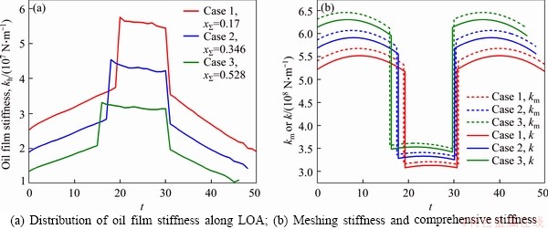
Figure 6 Stiffness characteristic curves:
Figure 7 shows the numerical difference of dynamic characteristics between coupling and uncoupling solutions. The meshing stiffness and comprehensive stiffness increased constantly with an increase in the sum of the modification coefficients, which led to a decreasing difference of dynamic transmission error (δcoupling-δuncoupling) and vibration velocity (ucoupling-uuncoupling).
Figure 8 shows the dynamic load spectrum of the gear system, representing the variation of the dynamic meshing force between the gear teeth. When the sum of the modification coefficients was fixed, compared to the dynamic load without coupling, the vibration amplitude of the dynamic load with coupling increased, and the vibration frequency decreased significantly. The engage-in impact (at point A) and tooth-change impact (at points B and C) intensified after the coupling. For a gear system with a high speed and heavy duty, because of the coupling effect of the oil film stiffness, it is necessary to analyze the vibration characteristics of the gear system and then analyze its lubrication characteristics.
Figure 8(d) shows the variation of the dynamic load for three different modification coefficients. After coupling, the comprehensive stiffness increased constantly with the increase in the sum of the modification coefficients, which led to a decrease in the steady value and vibration amplitude of the dynamic load and a significant increase in the vibration frequency. A larger modification coefficient could mitigate the engage-in impact and tooth-change impact of the gear system to stabilize the transmission.
4.2.2 Analysis for lubrication based on dynamic model
Figure 9 shows the comparison of the lubrication characteristics under different modification coefficients.
Figure 9(a) shows the distribution of the minimum oil film thickness along the LOA. Increasing the modification coefficients led to an increase in the oil film thickness. The vibration amplitude of the minimum oil film thickness increased, while its vibration frequency decreased, which indicates that the oil film stiffness decreased with the increase in the modification coefficient. This is consistent with the conclusion in Figure 6(a).
The friction coefficient and flash temperature were mainly affected by the load. As shown in Figures 9(b) and (c), with the increase in the sum of the modification coefficients, the vibration amplitude of the flash temperature and friction coefficient increased, while the vibration frequency decreased.
According to the results in Figure 9, at the engage-in point A and the alternation point B, due to the presence of a dynamic load, the flash temperature of the oil film had a maximum value, and the oil film thickness had a minimum value, which was prone to cause scuffing failure. Therefore, the gear tooth profile must be modified to reduce the dynamic load so that the scuffing load capacity of the gear system can be enhanced.
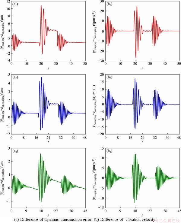
Figure 7 Difference of dynamic characteristic curves:
Figure 10 shows the transient temperature variations at point D for different modification coefficients. When the sum of modification coefficients was fixed, as the oil film became thicker, the transient temperature became higher. Thus, the transient temperature of the oil film center was much higher than that of two boundaries. This was because the squeezing effect was the strongest in the center of oil film, and the heat conducted from oil film center to the teeth to maintain the bulk temperature. As shown in Figure 10, the instantaneous temperature of the oil film decreased gradually with the increase in the modification coefficients.
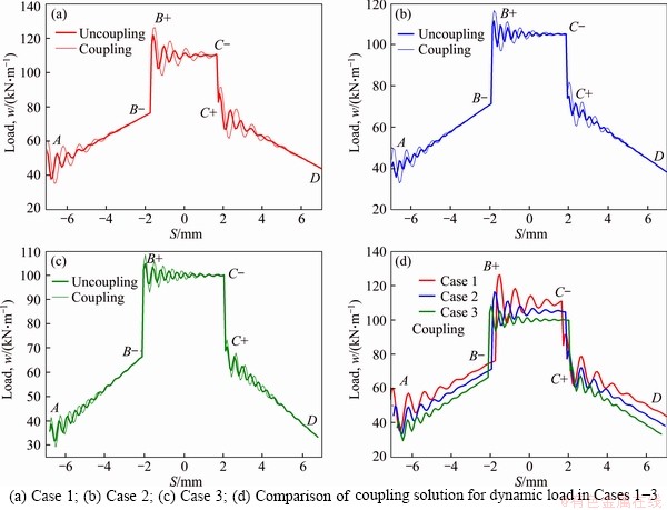
Figure 8 Coupling and uncoupling solution of dynamic load in:
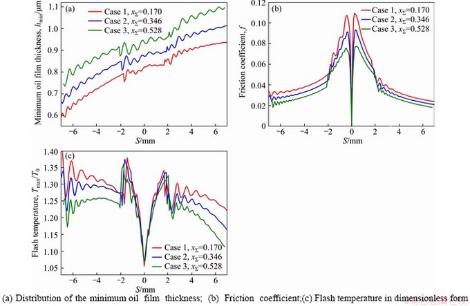
Figure 9 Comparison of lubrication characteristics for different modification coefficients:
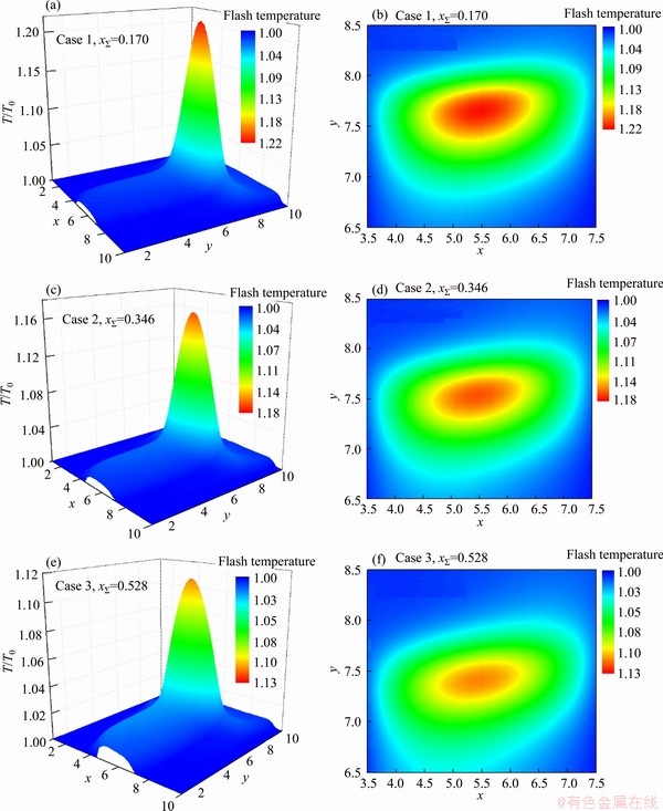
Figure 10 Transient temperature distribution at point D
5 Conclusions
Considering the modification coefficient, vibrations, and oil film stiffness, the thermal elastohydrodynamic lubrication performance of the high-speed heavy-duty gear system was analyzed based on a simplified static model and a dynamic model. The conclusions were as follows:
1) Compared with the standard drive, the positive drive could improve the lubrication condition of the gear system and enhance the scuffing load capacity. However, the negative drive caused the lubrication condition to worsen and undermined the scuffing load capacity.
2) When positive drive was adopted, with the increase in the modification coefficient, the oil film thickness increased, whereas the friction coefficient and flash temperature of the oil film decreased consistently. This indicates that the lubrication performance was continuously improved, and the scuffing load capacity was further enhanced.
3) For a high-speed heavy-duty gear system, lubrication has a great influence on its vibrations. The vibrations and lubrication should be studied together.
Contributors
The overarching research goals were developed by JIAN Guang-xiao and WANG You-qiang. JIAN Guang-xiao and WANG You- qiang put forward the research ideas. JIAN Guang- xiao, WANG You-qiang, ZHANG Ping, LI Yun-kai and LUO Heng established the models. JIAN Guang-xiao debugged the program, got the research data and accomplished the relevant analysis. The initial draft of the manuscript was written by JIAN Guang-xiao. All authors replied to reviewer’ comments and revised the final version.
Conflict of interest
JIAN Guang-xiao, WANG You-qiang, ZHANG Ping, LI Yun-kai and LUO Heng declare that they have no conflict of interest.
References
[1] WANG Jian-jun, LI Qi-han, LI Run-fang. Research advances for nonlinear vibration of gear transmission systems [J]. Advances in Mechanics, 2005, 35(1): 37-51. (in Chinese)
[2] SEIREG A, HOUSER D. Evaluation of dynamic factors for spur and helical gears [J]. ASME J Eng Ind, 1970, 1: 504-515. DOI: 10.1115/1.3427790.
[3] SAKARIDIS E, SPITAS V, SPITAS C. Non-linear modeling of gear drive dynamics incorporating intermittent tooth contact analysis and tooth eigenvibrations [J]. Mechanism and Machine Theory, 2019, 136: 307-333. DOI: 10.1016/j.mechmachtheory.2019.03.012.
[4] YAO Wen-xi. Meshing impact response of involute spur gears [J]. Vibration, Testing and Diagnosis, 1992, 12(2): 27-30. DOI: 10.16450/j.cnki.issn.1004-6801.1992.02.006. (in Chinese)
[5] HUA Dong-yun, ZHANG He-hao, XU Dong. A research on dynamics of rotator-gearing system [J]. Journal of Shanghai University of Technology, 1990, 11(2): 124-134. (in Chinese)
[6] ZHAO Jing-jing, WANG You-qiang, ZHANG Ping, JIAN Guang-xiao. A Newtonian thermal elastohydrodynamic lubrication model for ferrofluid-lubricated involute spur gear pair [J]. Lubrication Science, 2020, 32(2): 33-45. DOI: 10.1002/ls.1483.
[7] WANG Wen-zhong, CAO Hong. Numerical simulation of unsteady EHL lubrication of involute helical gears [J]. Tribology, 2011, 31(6): 604-609. DOI: 10.16078/j.tribology. 2011.06.015. (in Chinese)
[8] DAI Ling, PU Wei, WANG Jia-xu. Mixed EHL analysis of planetary drives with small teeth number difference considering real tooth geometry [J]. Lubrication Science, 2018, 30(6): 317-330. DOI: 10.1002/ls.1423.
[9] LIU Huai-ju, ZHU Cai-chao, SUN Zhang-dong, SONG Chao-sheng. Starved lubrication of a spur gear pair [J]. Tribology International, 2016, 94: 52-60. DOI: 10.1016/ j.triboint.2015.07.030.
[10] GLOVNEA R, ZHANG Xing-nan. Elastohydrodynamic films under periodic load variation: An experimental and theoretical approach [J]. Tribology Letters, 2018, 66(3): 1-11. DOI: 10.1007/s11249-018-1067-1.
[11] LU Li-xin, ZHANG He-hao. Nonsteady elasto- hydrodynamic lubrication of Gear Transmission system under dynamic load [J]. Lubrication Engineering, 2002, 27(1): 12-14. (in Chinese)
[12] LIU Huai-ju, MAO Ken, ZHU Cai-chao, CHEN Si-yu, XU Xiang-yang, LIU Ming-yong. Spur gear lubrication analysis with dynamic loads [J]. Tribology Transactions, 2013, 56(1): 41-48. DOI: 10.1080/10402004.2012.725805.
[13] WANG K L, CHENG H S. A numerical solution to the dynamic load, film thickness, and surface temperatures in spur gears, part I: Analysis [J]. Journal of Mechanical Design, 1981, 103(1): 177-187. DOI: 10.1115/1.3254859.
[14] WANG K L, CHENG H S. A numerical solution to the dynamic load, film thickness, and surface temperatures in spur gears, Part II: Results [J]. Transactions of the ASME, 1981, 103(1): 188-194. DOI: 10.1115/1.3254860.
[15] SHI Gao-wei, WANG You-qiang. Influence of variable coiling and suction speed process on hot mixed lubrication of spur gear [J]. Lubrication Engineering, 2011, 36(1): 43-48. DOI: 10.3969/j.issn.0254 -0150.2011.01.012. (in Chinese)
[16] YANG Yu-liang. Research on thermo-elastic coupling and vibration damping with modification of helical gear system [D]. Dalian, Dalian University of Technology, 2016. (in Chinese)
[17] ZHANG Zhao-qiang. Study on elastohydrodynamic lubrication and dynamics contact of double involute gear [D]. Qingdao: Qingdao University of Science & Technology, 2014. (in Chinese)
[18] WANG You-qiang, CHANG Tong. The influence of approach impact load on elasto-hydrodynamic lubrication of involute spur gears [J]. Chinese Journal of Computational Mechanics, 2010, 27(3): 527-532. (in Chinese)
[19] ZHAO Jing-jing, WANG You-qiang. Non-steady-state EHL analysis of impact load in involute spur gear under different carrier fluid ferrofluid [J]. Machine Tool & Hydraulics, 2019, 47(22): 20-23, 40. DOI: 10.3969/j.issn.1001-3881.2019.22. 004. (in Chinese)
[20] WANG You-qiang, HE Zhi-cheng, SU Wei. Effect of impact load on transient elastohydrodynamic lubrication of involute spur gears [J]. Tribology Transactions, 2012, 55(2): 155-162. DOI:10.1080/10402004.2011.639048.
[21] de la CRUZ M, CHONG W W F, TEODORESCU M, THEODOSSIADES S, RAHNEJAT H. Transient mixed thermo-elastohydrodynamic lubrication in multi-speed transmissions [J]. Tribology International, 2012, 49: 17-29. DOI: 10.1016/j.triboint.2011.12.006.
[22] XUE Jian-hua, LI Wei, QIN Cai-yan. The scuffing load capacity of involute spur gear systems based on dynamic loads and transient thermal elastohydrodynamic lubrication [J]. Journal of Central South University (Science and Technology), 2014, 42: 32-44. (in Chinese)
[23] JIAN Guang-xiao, WANG You-qiang, ZHANG Ping, XIE Yi-nong. Analysis of lubricating performance for involute spur gear under vibration [J]. Lubrication Science, 2020, 32(7): 344-357. DOI: 10.1002/ls.1507.
[24] LI S, KAHRAMAN A. A spur gear mesh interface damping model based on elastohydrodynamic contact behaviour [J]. International Journal of Powertrains, 2011, 1(1): 4-21. DOI: 10.1504/ijpt.2011.041907.
[25] LI S, KAHRAMAN A. A tribo-dynamic model of a spur gear pair [J]. Journal of Sound and Vibration, 2013, 332(20): 4963-4978. DOI: 10.1016/j.jsv.2013.04.022.
[26] BARBIERI M, LUBRECHT A A, PELLICANO F. Behavior of lubricant fluid film in gears under dynamic conditions [J]. Tribology International, 2013, 62: 37-48. DOI: 10.1016/ j.triboint.2013.01.017.
[27] MA Ru-kang. A study of quasi-static and dynamic behavior of double helical gears [M]. Ohio: The Ohio State University, 2014.
[28] HUANG Xing-bao, YANG Bin-tang, WANG You-qiang. A nano-lubrication solution for high-speed heavy-loaded spur gears and stiffness modelling [J]. Applied Mathematical Modelling, 2019, 72: 623-649. DOI: 10.1016/j.apm.2019. 03.008.
[29] ZHANG Yuan-yuan, LIU Huai-ju, ZHU Cai-chao, LIU Ming-yong, SONG Chao-sheng. Oil film stiffness and damping in an elastohydrodynamic lubrication line contact-vibration [J]. Journal of Mechanical Science and Technology, 2016, 30(7): 3031-3039. DOI: 10.1007/s12206- 016-0611-x.
[30] ZHOU Chang-jiang, XIAO Ze-liang, CHEN Si-yu, HAN Xu. Normal and tangential oil film stiffness of modified spur gear with non-Newtonian elastohydrodynamic lubrication [J]. Tribology International, 2017, 109: 319-327. DOI: 10.1016/j.triboint.2016.12.045.
[31] LEI Chun-li, LI Fu-hong, GUO Jun-feng, YANG Xiao-yan. Analysis on the oil film stiffness of rolling bearings based on multi parameter coupling [J]. Journal of Vibration and Shock, 2018, 37(10): 225-232. DOI: 10.13465/j.cnki.jvs.2018.10. 032. (in Chinese)
[32] ZOU Yu-jing, CHANG De-gong. Coupling analysis of dynamics and EHL for spur gears [J]. Journal of Aerospace Power, 2016, 31(4): 2010-2020. DOI: 10.13224/j.cnki.jasp. 2016.08.028. (in Chinese)
[33] ZOU Yu-jing. Coupling research on dynamical behavior and elastohydrodynamic lubrication property of helical gear [J]. Journal of Mechanical Engineering, 2019, 55(3): 109-117. DOI: 10.3901/jme.2019.03.109. (in Chinese)
[34] LIU Fu-hao, JIANG Han-jun, ZHANG Liang, CHEN Li. Analysis of vibration characteristic for helical gear under hydrodynamic conditions [J]. Advances in Mechanical Engineering, 2017, 9(1): 168781401668796. DOI: 10.1177/ 1687814016687962.
[35] LIU Fu-hao, JIANG Han-jun, LIU Shao-na, YU Xue-hua. Dynamic behavior analysis of spur gears with constant & variable excitations considering sliding friction influence [J]. Journal of Mechanical Science and Technology, 2016, 30(12): 5363-5370. DOI: 10.1007/s12206-016-1103-8.
[36] YUAN Shi-hua, DONG Hui-li, LI Xue-yuan. Analysis of lubricating performance for involute gear based on dynamic loading theory [J]. Journal of Mechanical Design, 2012, 134(12): 1-9. DOI: 10.1115/1.4007842.
[37] DONG Hui-li, YUAN Shi-hua, HU Ji-bin, LI Xue-yuan. Analysis of lubricating performance for involute gear considering tribo-dynamic behavior [J]. 2013, 33(5): 436- 442. DOI: 10.16078/j.tribology.2013.05.012. (in Chinese)
[38] YUAN Shi-hua. Dynamic loading analysis of involute gears considering lubrication performance [J]. Journal of Mechanical Engineering, 2012, 48(19): 10-16. DOI: 10.3901/jme.2012.19.010. (in Chinese)
[39] LI Run-fang, WANG Jian-jun. Gear system dynamics [M]. Beijing: Science press, 1997. (in Chinese)
[40] TANG Jin-yuan, CAI Wei-xing, WANG Zhi-wei. Meshing stiffness formula of modification gear [J]. Journal of Central South University (Science and Technology), 2017, 48(2): 337-342. DOI: 10.11817/j.issn.1672-7207.2017.02.010. (in Chinese)
[41] WANG You-qiang, YANG Pei-ran. Analysis of Transient Micro-Thermoelastic Flow of Involute Spur Gears [J]. Journal of Mechanical Engineering, 2007, 43(11): 142-148. (in Chinese)
[42] YANG Pei-ran. Numerical analysis of fluid lubrication [M]. Beijing: National Defense Industry Press, 1998. (in Chinese)
[43] LUO Biao. Investigation of thermo-elastic coupling dynamics and multi-objective comprehensive tooth profile modification of gear transmission system [D]. Beijing: University of Science and Technology Beijing, 2019. (in Chinese)
(Edited by ZHENG Yu-tong)
中文导读
考虑振动的变位齿轮系统热弹流润滑
摘要:为了探究动载荷作用下变位齿轮系统的热弹流润滑特性,综合考虑齿轮变位和振动的影响,基于动力学理论,建立了齿轮的六自由度摩擦动力学模型,分析振动与静载荷作用下变位齿轮系统的热弹流润滑特性。研究表明,与其他传动类型相比,正传动齿轮系统的润滑效果最佳,轮齿间可以形成较厚的润滑油膜,轮齿间的摩擦因数、油膜的最高温升最小,并且,随着两齿轮变位系数和的增大,润滑状况不断得到改善,热胶合承载能力增强;变位系数增加使齿轮系统的刚度增大,但同时也降低了油膜的刚度。
关键词:渐开线直齿轮;摩擦动力学模型;油膜刚度;变位系数;润滑特性
Foundation item: Projects(51575289, 51705270) supported by the National Natural Science Foundation of China
Received date: 2020-03-30; Accepted date: 2020-06-29
Corresponding author: WANG You-qiang, PhD, Professor; Tel: +86-18660279607; E-mail: wyq1970301@126.com; ORCID: https:// orcid.org/0000-0001-9228-6621

