J. Cent. South Univ. (2016) 23: 555-561
DOI: 10.1007/s11771-016-3102-4

A novel ring vibrating gyroscope based on side piezo-electrodes
ZHOU Xin(周鑫)1, WU Yu-lie(吴宇列)1, WU Xue-zhong(吴学忠)1,
ZHANG Yong-meng(张勇猛)1, ZHENG Yu(郑煜)2
1. College of Mechatronics Engineering and Automation,
National University of Defense Technology, Changsha 410073, China;
2. State Key Laboratory of High Performance Complex Manufacturing
(Central South University), Changsha 410083, China
 Central South University Press and Springer-Verlag Berlin Heidelberg 2016
Abstract: Solid-state wave gyroscope is one kind of high-performance vibrating gyroscopes. The present work develops a new type of solid-state wave gyroscope―a ring vibrating gyroscope driven by piezo-electrodes located on the sidewall of the structure. It has advantages of large vibrating amplitude, high energy conversion efficiency and compact structure. The working principle of the piezoelectric ring vibrating gyroscope is based on the inertia effect of the standing wave in the axisymmetric resonator caused by Coriolis force. The finite element method (FEM) analysis has been implemented to characterize the ring type resonator. The prototypal gyroscope was manufactured and has been trimmed by mechanical way. The harmonic response of the ring vibrating gyroscope has been tested. The resonating frequency of the ring type resonator is 3715.6 Hz and the frequency split of the two working modes before trimming was about 5 Hz and was reduced to sub -0.01 Hz after trimming procedure. The Q-factor of the ring type resonator was 2504. Then, the turntable experiment was implemented. The measured scale factor k is 9.24 mV/[(°)・s] and the full scale range of the gyroscope is larger than ±300 (°)/s.
Key words: solid-state wave gyroscope; piezoelectric gyroscope; side drive; ring vibrating gyroscope
1 Introduction
Solid-state wave gyroscope is one kind of high-performance vibrating gyroscopes. The principle of the solid-state wave gyroscope was first found by Bryan in 1890 [1]{Bryan, 1890 #224;Bryan, 1890 #224}. There are all kinds of solid-state wave gyroscopes. Almost all of them utilize axisymmetric resonators. Solid-state wave gyroscope shows its superiority in size, accuracy, shock resistance, and operation life [2]. It has been widely used in space applications, avionics systems, naval equipments and land vehicle control.
Many types of solid-state wave gyroscopes have been developed. These gyroscopes are usually actuated and sensed by methods including electrostatics, electromagnetics and piezoelectricity.
The typical electrostatic actuation/sensing solid-state wave gyroscope is the hemispherical resonating gyroscope (HRG) which remains to be the most accuracy vibrating gyroscope [3-4]. But HRG has drawbacks such as complex structure, high manufacturing requirements, high cost and high power consumption due to its electrostatic principle.
An electromagnetic actuation/sensing solid-state wave gyroscope was reported in Ref. [5]. This electromagnetic gyroscope needs a magnet to produce magnetic field which complicate the assembling procedure. And the electromagnetic actuation/sensing way is not very efficient and is fragile to the electromagnetic interference from outside.
Many solid-state wave gyroscopes utilize the piezoelectric principle as well because piezoelectric transducer shows its advantages of large amplitude, high linearity, and high energy conversion efficiency [6]. The typical product is the cylinder shell vibrating gyroscope [7-8]. This type of gyroscope utilizes a cylinder shell with a bottom plane as the resonator. The piezo- electrodes located on the bottom of the shell and the inertial proof mass-the vibrating ring located on the top of the shell are not in the same plane. So, there may be an offset between the eigenmodes axis of the resonating ring and the exciting axis, lying on the distribution of the piezo-electrodes. And this offset could cause errors to the gyroscope [9]. Never the less, the precise thin-wall structure is hard to machining.A ring type gyroscope was reported which utilizes cage-like resonator as the sensing element [10]. It is hard to guarantee the uniformity of the supporting beams of this ring type resonator which would affect the symmetry of the structure.
A kind of piezoelectric MEMS solid-state wave gyroscope was also developed [11]. But this piezoelectric gyroscope makes use of the piezoelectric material’s contracting and expanding deformation which could only produce very small displacement to actuate or sense the resonator’s working mode. Therefore, the vibrating amplitude of the resonator is limited.
This work is aimed at developing a new type of piezoelectric ring vibrating gyroscope. The piezo- electrodes are located on the sidewall of the ring type structure, which makes the best use of the piezo- electrode’s bending deformation to actuate or sense the resonator’s working mode. Therefore, it has advantages of large vibrating amplitude, high energy conversion efficiency and simple compact structure. The resonator is easy to manufacture and the cost of the gyroscope is low. Furthermore, the plane characteristic of the ring type resonator makes it potential for MEMS craft.
2 Design concepts
2.1 Structure design
The structure schematic of the piezoelectric ring vibrating gyroscope is illustrated in Fig. 1. The ring resonator consists of a vibrating ring, 8 supporting springs, 8 piezo-electrodes and an anchor. The anchor is fixed tightly. The vibrating ring is connected with the anchor by eight supporting springs. The supporting springs is thinner than the vibrating ring. The piezo-electrodes are attached on the sidewall of the supporting springs which work as both actuators and transducers. The overall structure is symmetrical about z axis.
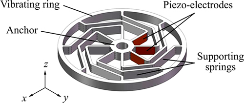
Fig. 1 structure schematic of piezoelectric ring vibrating gyroscope
2.2 Working principle
This piezoelectric ring vibrating gyroscope belongs to the solid-state wave gyroscope. The working principle of the piezoelectric side drive vibrating gyroscope is based on the inertia effect of the standing wave in the axisymmetric resonator caused by Coriolis force. The working principle is illustrated in Fig. 2. The n=2 wineglass modes which stand for the modes in the form of standing waves with the circumferential wave number being 2 of the ring are used as the working modes. There are a couple of n=2 wineglass modes on the resonating ring which circumferentially spaced relative to each other 45°. The 1st n=2 wineglass mode deforms in the x-O-y axes frame, while the 2nd n=2 wineglass mode deforms in the x'-O-y' axis frame. One of the n=2 wineglass mode, say the 1st n=2 wineglass mode is excited continuously working as the actuating mode. When the resonating ring rotates along the z axis, the 2nd n=2 wineglass mode which works as the sensing mode will be detected due to the Coriolis effect.
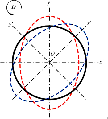
Fig. 2 working principle of piezoelectric ring vibrating gyroscope
The working modes of the ring type resonator are actuated and sensed by the piezo-electrodes attached on the sidewall of the supporting springs. One single piezo- electrode is a sandwich structure which consists of two metal layers and a piezoelectric layer between them. Generally speaking, there are two kinds of piezoelectric working modes: the stretching mode and the bending mode.
In the stretching mode, when a driving voltage Vd is applied between the piezo-electrode’s upper and lower metal layers, the block piezo-electrode’s contracting and expanding deformation will drive the passive element to move back and forth or stretch out and draw back. And the linear movement of the passive element can cause a sensing voltage Vs.
The bending mode is illustrated in Fig. 3. The lamellar piezo-electrode is attached on the passive elastic layer. Those components constitute a multilayer composite structure. The contracting and extension of the piezo-electrode produce bending deformation on the composite structure when a driving voltage Vd is applied between the piezo-electrode’s upper and lower metal layers. And the bending deformation of the composite structure can cause a sensing voltage Vs. The bending actuation mode has following advantages: large excursions in bending structures, low driving voltage, high energy conversion efficiency, low noise and good frequency response ability. This ring vibrating gyroscope is actuated and sensed by lateral piezo-electrodes working on the bending mode.
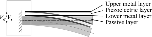
Fig. 3 piezo-electrode’s bending working mode
Each supporting spring attached with piezo- electrode makes up a composite structure just like the structure illustrated in Fig. 3, and transforms the bending excursion into the ring’s elliptical deformation. When direct voltage Vd is simultaneously applied on a pair of opposite piezo-electrodes and -Vd on the pair of piezo- electrodes perpendicular to them, the static elliptical deformation of the ring type resonator can be generated. This can be simulated by ANSYS static analysis, Fig. 4(a). When a alternating voltage Vd0sin(ωt) instead of the direct voltage Vd is applied on the actuation piezo- electrodes, the n=2 wineglass mode of the ring type resonator could be excited if the ω is close to the eigenfrequency of the resonator. This can be simulated by ANSYS harmonic analysis, Fig. 4(b). The detail of the harmonic analysis will be represented later. In fact, two opposite positioned piezo-electrodes can stimulate the n=2 wineglass mode of the ring type resonator and the other two piezo-electrodes perpendicular to themcould provide negative feedback to stabilize the vibration amplitude of the resonator.
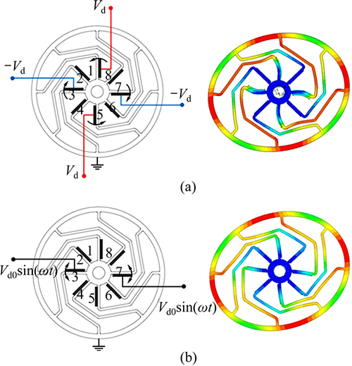
Fig. 4 actuation of ring type resonator simulated by ANSYS
3 Simulation analysis
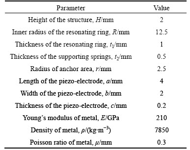
The FEM analysis was implemented to characterize the ring type resonator. The modal analysis and harmonic analysis are processed by simulation software ANSYS. Table 1 gives the geometric and physical parameter of the resonating structure used in the simulation.
Table 1 Geometric and physical parameters of resonating structure used in simulation
3.1 Model analysis
First, modal analysis was implemented to get the mode deformation and the corresponding frequency, Fig. 4. Only some correlative in-plane deformation modal is illustrated because those out-plane deformation can hardly be generated be the piezo-electrodes attached on the sidewall of the supporting springs.
This ring vibrating gyroscope uses n=2 wineglass mode as the working mode, illustrated as mode 4 and mode 5 in Fig. 5. Mode 1 (Torsion mode) may most probably disturb the working mode because when static voltage is applied in any of the piezo-electrodes, the structure will twist around the anchor point. The best way to stimulate the n=2 wineglass mode is to apply alternating voltage whose frequency matchs that of n=2 wineglass mode onto the actuation piezo-electrodes. It can be seen that the frequency of torsion mode differs greatly from n=2 wineglass mode which can help to get rid of the torsion displacement while operating. Modes 2 and 3 are the translation deformation. Modes 7 and 8 are the n=3 wineglass mode. Those modes are not likely to disturb the working mode.
3.2 Angular response analysis
In order to verify the working principle, the harmonic coupled field analysis was processed. In this analysis, how the piezo-electrodes actuate and sense the deformation based on piezoelectric effect was simulated. As described above, the piezo-electrodes are attached to the sidewall of the supporting springs, as shown in Fig. 6. The piezo-electrodes are made of PZT-5H, which is designed by piezoelectric equations as follows:
T=cE・S-eT・E
D=e・S+εS・E
where S and T are strain tensor and stress tensor of the elastic structure field, respectively; D and E are electric displacement vector and electric field intensity, respectively; cE is the elastic stiffness tensor at constant electric field; εS is the dielectric permittivity tensor at constant stress; e is piezoelectric stress tensor constant; eT is transposition matrix of e. Specifically, for transverse effect piezo-electrode poled in the thickness direction (w direction), we have the following coupling field matrixes cE, e and εS:


The subscripted numbers with the above symbols denote the related directions; 1, 2, 3 refer to the u, v, w directions of the local coordinate, and 4, 5, 6 refer to the v-w, u-w, u-v directions, respectively.
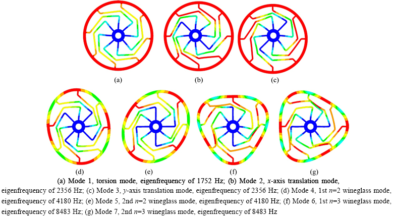
Fig. 5 deformation of each mode:
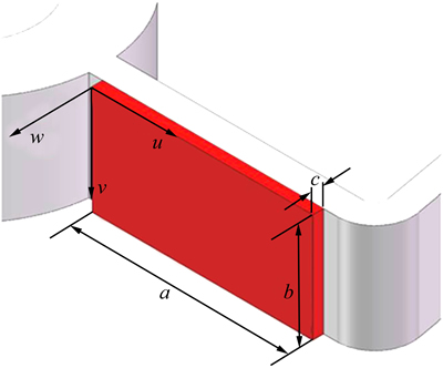
Fig. 6 Dimension and general coordinate of piezo-electrodes attached to side surface of supporting springs
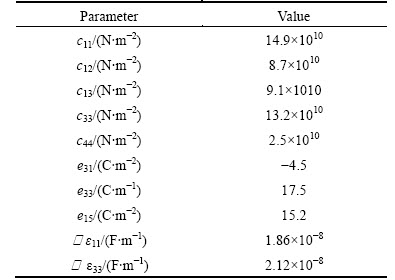
Table 2 gives the properties of PZT-5H piezo-electrodes used in the coupling field simulation.
The alternating driving voltage was brought to the pair of actuation piezo-electrodes. If the frequency of the alternating driving voltage is close to the eigenfrequency of the n=2 working mode, the n=2 wineglass mode can be stimulated.
Table 2 coupling field properties of PZT-5H
If the Coriolis effect was introduced in the harmonic coupled field analysis, the gyroscopic angular response can be simulated. When driving voltage is applied on the actuation piezo-electrodes, the driving mode―the 1st n=2 wineglass mode, is stimulated. If the input angular velocity Ω is not zero, the sensing mode―the 2nd n=2 wineglass mode will be stimulated by the Coriolis force. The output sensing voltage Vs is then produced on the sensing piezo-electrodes. And Vs is proportional to the input angular velocity Ω. In the analysis, the damping ratio was set to be 5×10⁻⁵, which means that the Q-factor is 10000. The input-output line of the gyroscope was acquired and the scale factor was calculated to be 21.22 mV/[(°)・s] by the linear fitting method, Fig. 7.
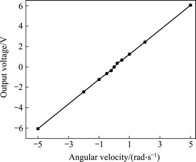
Fig. 7 input-output line of gyroscope acquired by simulation
4 Experiments
4.1 Fabrication
The ring type resonator can be manufactured by many methods such as meso-scale precision mechanical machining process [12-13] and precision wire cut electrical discharge machining process [14]. In this work, the ring type resonator was manufactured by precision wire cut electrical discharge machining, Fig. 8(a). The geometric parameters of the manufactured resonator are the same as those of the analyzing ring resonator, Table 1. The ring type resonator of the prototypal gyroscope is made of constant elastic alloy such as Ni42CrTi and Ni-SPAN-С Alloy 902 in order to achieve high Q-factor and high vibration stability. The piezo-electrodes were adhered to the side of each supporting springs with conductive adhesive. Then, the ring type resonator with piezo-electrodes was assembled to a substrate. After that, the bonding procedure was implemented to connect the piezo-electrodes with soldering board on the substrate. The prototypal piezoelectric ring vibrating gyroscope is illustrated in Fig. 8(b).
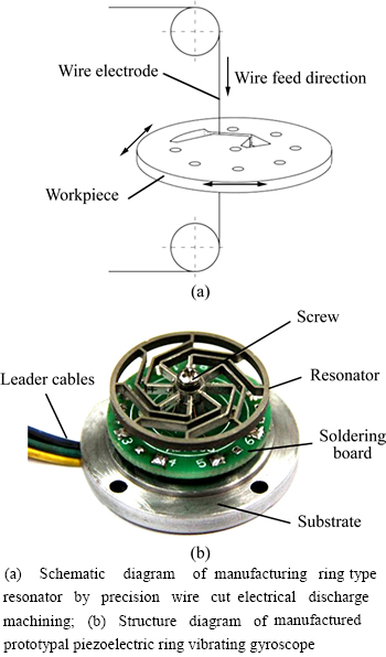
Fig. 8 manufacture and structure of prototypal piezoelectric ring vibrating gyroscope:
4.2 Frequency response analysis
The harmonic response of the ring vibrating gyroscope is tested using a NF FRA5087 frequency response analyzer. The gyroscope operated in atmospheric environment during the test. The driving voltage is applied on piezo-electrodes 1 and 5, and the response voltage is picked up from piezo-electrodes 3 and 7. The resonating response curve is shown in Fig. 9. From the response curve we can see that the resonating frequency of the ring type resonator is 3715.6 Hz, which is coincident well the result of the mode analysis (4180 Hz). The Q-factor of the resonator deduced from the data is 2504.
4.3 Mechanical trimming
There is a frequency split between the actuating mode and the sensing mode due to the geometrical imperfection caused by the manufacturing errors. The frequency split of the prototypal gyroscope was tested to be about 5 Hz. Mechanical balancing methods are usually employed to eliminate the frequency split. Some grooves were opened on the resonator for accurate material removing. These trimming structures can significantly change local stiffness and mass distribution of the resonators. Thus, the frequency split can be reduced to a small value. After the mechanical balancing procedure the frequency split was reduced to sub -0.01 Hz [15].
4.4 control circuit
The control circuit plays an important role in the overall performance of the gyroscope. Figure 10 shows the block diagram and photo of the proposed control electronics which includes an excitation control loop, a force-balance control loop and a velocity demodulation block.
The excitation control loop excites the driving mode of the resonator and keeps the vibration amplitude at a constant value automatically. The force-balance loop compensates for the Coriolis force induced by input angular velocity and restrains the sensing mode of the resonator, which improves the angular velocity response bandwidth of the gyroscope. The velocity demodulation block demodulates the compensating signal and exports the output signal which is proportional to the input angular velocity.
4.5 Performance test
The ring type gyroscope was fixed on a high-precision turntable. The rotation velocity of the turntable is controlled by a PC controller, and the output signal is sampled by an Agilent 34410A multimeter. The output signal with respect to the rotation velocity up to 300 (°)/s in both clockwise and counterclockwise is obtained. The output sensing voltages under different input angular velocities are listed in Table 3 and depicted in Fig. 11 (minus velocity values indicate it’s counterclockwise). The linear relation can be deduced as

The measured scale factor k is 9.24 mV/[(°)・s]. And the full scale range of the gyroscope is larger than ±300 (°)/s. The bias voltage Vs0 of the prototypical gyroscope is 2.34 V. The large bias is mostly caused by the coupling of the torsion mode and the n=2 wineglass mode.
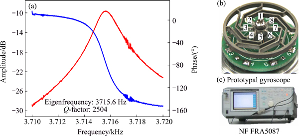
Fig. 9 harmonic response of ring vibrating gyroscope (a) and frequency response experiment setup (b, c)
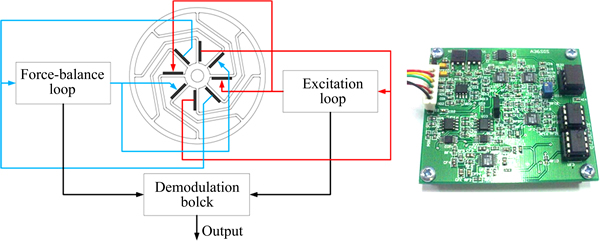
Fig. 10 block diagram and photograph of control circuit
Table 3 Output sensing voltages vs input angular velocity
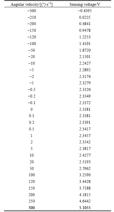
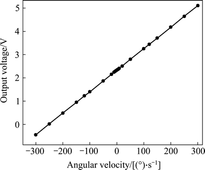
Fig. 11 input-output line of gyroscope acquired by test
5 Conclusions
A novel low-cost meso-scale piezoelectric ring vibrating gyroscope based on side driving piezo-electrodes has been designed, simulated and characterized. The piezoelectric ring vibrating gyroscope is actuated and sensed by piezo-electrodes located on the sidewall of the resonating structure. The working principle is verified by FEM simulation and experiments. Prototypal gyroscope is manufactured and characterized. The resonating frequency of the ring type resonator is 3715.6 Hz and the frequency split of the two working mode before trimming is about 5 Hz which was reduced to sub -0.01 Hz after trimming procedure. The Q-factor of the ring type resonator is 2504. The measured scale factor k is 9.24 mV/[(°)・s]. And the full scale range of the gyroscope is larger than ±300 (°)/s.
References
[1] BRYAN G H. On the beats in the vibrations of a revolving cylinder or bell [J]. Cambridge Phil Soc, 1890, VII(III): 101.
[2] MATTHEWS A, RYBAK F J. Comparison of hemispherical resonator gyro and optical gyros [J]. IEEE AES MAGAZINE, 1992, 7(5): 40-45.
[3] DICKINSON J, STRANDT C R. HRG strapdown navigator [C]// Proceedings of the Position Location and Navigation Symposium, 1990 Record The 1990’s―A Decade of Excellence in the Navigation Sciences IEEE PLANS '90, IEEE, 1990: 110-117.
[4] MEYER A D, ROZELLE D M. Milli-HRG inertial navigation system [C]// Proceedings of the Position Location and Navigation Symposium (PLANS), 2012 IEEE/ION, 2012: 24-29.
[5] HOPKIN I D, FELL C P, TOWNSEND K, et al. Vibrating Structure gyroscope: US, 5932804 [P]. 1999.
[6] DRIESEN W, BERGANDER A, VARIDEL T, BREGUET J M. Energy consumption of piezoelectric actuators for inertial drives [C]// Proceedings of the Micromechatronics and Human Science, 2003 MHS 2003 Proceedings of 2003 International Symposium on, 2003: 51-58.
[7] CHIKOVANI V V, OKON I M, BARABASHOV A S, TEWKSBURY P. A set of high accuracy low cost metallic resonator CVG [C]// Proceedings of the Position, Location and Navigation Symposium, 2008 IEEE/ION, 2008: 238-243.
[8] CHIKOVANI V V, YATSENKO Y A, BARABASHOV A S, MARUSYK P I, UMAKHANOV E Q, TATURIN V N. Improved accuracy metallic resonator CVG [J]. Aerospace and Electronic Systems Magazine, IEEE, 2009, 24(5): 40-43.
[9] XI Xiang, WU Yu-lie, WU Xiao-mei, TAO Yi, WU Xue-zhong. Investigation on standing wave vibration of the imperfect resonant shell for cylindrical gyro [J]. Sensors and Actuators A: Physical, 2012, 179(0): 70-77.
[10] TAO Yi, WU Xue-zhong, XIAO Ding-bang, WU Yu-lie, CUI Hong-juan, XI Xiang, ZHU Bing-jie. Design, analysis and experiment of a novel ring vibratory gyroscope [J]. Sensors and Actuators A: Physical, 2011, 168(2): 286-299.
[11] IKEDA T, NISHIDA H, TORAKASHIKI O, TAKEMURA M, FUJIMURA T, ARAKI R, MORIGUCHI, TESHIMA N, HIRATA Y. Vibratory gyroscope using piezoelectric film: US, 8601872 B2 [P]. 2013.
[12] KAWAI T, SAWADA K, TAKEUCHI Y. Ultra-precision micro structuring by means of mechanical machining [C]// Proceedings of the Micro Electro Mechanical Systems, 2001 MEMS 2001 The 14th IEEE International Conference on: Interlaken: IEEE, 2001: 22-25.
[13] TAKEUCHI Y, SAWADA K, SATA T. Computer aided ultra-precision micro-machining of metallic materials [C]// Proceedings of the Robotics and Automation, 1995 Proceedings, 1995 IEEE International Conference on Nagoya: IEEE, 1995: 67-72.
[14] MEEUSEN W, CLIJNEN J, REYNAERTS D, BRUSSEL V H, PUERS R. Micro-electro-discharge machining as microsensor fabrication technology [J]. Sensors Journal, IEEE, 2003, 3(5): 632-639.
[15] TAO Yi, XI Xiang, XIAO Ding-bang, TAN Ying-qi, CUI Hong-juan, WU Xue-zhong. Precision balance method for cupped wave gyro based on cup-bottom trimming [J]. Chin J Mech Eng, 2012, 25(1): 63-70.
(Edited by DENG Lü-xiang)
Foundation item: Projects(51335011, 51275522) supported by the National Natural Science Foundation of China; Project(HPCM-2013-08) supported by Key Lab Open Foundation of State Key Laboratory of High Performance (Complex Manufacturing), Central South University, China
Received date: 2014-12-24; Accepted date: 2015-04-20
Corresponding author: WU Yu-lie, PhD, Professor; Tel: +86-731-84574958; E-mail: ylwu_nudt@sina.com

