Ultrasonic vibrating system design and tool analysis
来源期刊:中国有色金属学报(英文版)2009年增刊第1期
论文作者:Kei-Lin KUO
文章页码:225 - 231
Key words:ultrasonic; milling; tool design
Abstract: The applications of ultrasonic vibrations for material removal processes exist predominantly in the area of vertical processing of hard and brittle materials. This is because the power generated by vertical vibrating oscillators generates the greatest direct penetration, in order to conduct material removal on workpieces by grains. However, for milling processes, vertical vibrating power has to be transformed into lateral (horizontal) vibration to produce the required horizontal cutting force. The objective of this study is to make use of ultrasonic lateral transformation theory to optimize processing efficiency, through the use of the finite element method for design and analysis of the milling tool. In addition, changes can be made to the existing vibrating system to generate best performance under consistent conditions, namely, using the same piezoelectric ceramics.

Kei-Lin KUO
Department of Vehicle Engineering, National Taipei University of Technology, Taipei 10608, China
Received 2 March 2009; accepted 30 May 2009
Abstract: The applications of ultrasonic vibrations for material removal processes exist predominantly in the area of vertical processing of hard and brittle materials. This is because the power generated by vertical vibrating oscillators generates the greatest direct penetration, in order to conduct material removal on workpieces by grains. However, for milling processes, vertical vibrating power has to be transformed into lateral (horizontal) vibration to produce the required horizontal cutting force. The objective of this study is to make use of ultrasonic lateral transformation theory to optimize processing efficiency, through the use of the finite element method for design and analysis of the milling tool. In addition, changes can be made to the existing vibrating system to generate best performance under consistent conditions, namely, using the same piezoelectric ceramics.
Key words: ultrasonic; milling; tool design
1 Introduction
The ultrasonic vibrating system model is complicated. Therefore, to understand ultrasonic power transfer, and determine the resonance frequency, swing and pressure distribution, we have selected finite element analysis software ANSYS to fully represent and model these factors. The power transfer of the ultrasonic vibrating system, resonance frequency, vibration swing and pressure distribution have been set by adjusting analysis parameters according to theory and experience. Results were observed and compared with theoretical values. It has been shown previously that the observed value is higher than the theoretical one in terms of swing and very close to the practical one in terms of frequency [1]. Early finite element analysis software was unable to fully simulate ultrasonic vibrating system dynamic reactions. Full simulation of the vibrating system has been achieved by adding a coupling element. TSUCHIYA and KAGAEA[2] used coupling elements to simulate a piezoelectric panel to analyze its polarization directional effect. The ultrasonic simulation analysis uses power input piezoelectric ceramics to convert an electric signal to structural strain, which makes the structure vibrate by harmonic movement, simulating the swing and structural pressure under working conditions. SHERRIT et al[3] used the finite element method to simulate the drilling processing performance. Previously, when computer systems were of insufficient capacity to do full modeling analysis, AMIN et al[4] used ANSYS to conduct half-modeling analysis, and showed that this dramatically reduced analysis time.
2 Finite element analysis setting
2.1 Simulation process
In this finite element analysis, the major factors used for modeling a general structural pressure simulation include element type, real constant, material properties, geometry, meshing, boundary conditions etc. After these factors have been set, the analysis may begin. The factors for analysis of an ultrasonic vibrating system are essentially the same, but with the addition of a piezoelectric parameter setting and the replacement of exterior pressure road by input power pressure.
2.1.1 Real modeling establishment
As the geometric structure of an oscillator is complex, the experimental process will be complex if the modeling is done in ANSYS. Therefore, in this study the 3D drawing software Autodesk Inventor (hereafter called Inventor) was used to construct the model.
The 2D axial symmetric graph of the oscillator was modeled in Inventor after size measurement, and is depicted in Fig.1. When drawing the 2D graph, special attention must be paid to the size and relative positions of components to avoid any mistake in ANSYS. Then, the 2D components were revolved around the axis of symmetry to produce 3D images representative of the real components, as shown in Fig.2. The produced 3D components must be converted into an ANSYS readable format. After integration into ANSYS, ANSYS will automatically determine the positional coordinates of various parts according to their relative positions in Inventor.
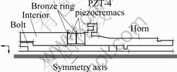
Fig.1 2D axial symmetric graph
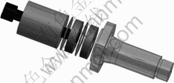
Fig.2 3D component images
2.1.2 Mode analysis
Mode analysis is the first analysis step. This allows full understanding of the working frequency scope and swing distribution of the ultrasonic vibrating system. It aids in reducing cost and time requirements when designing the oscillator. The swing obtained by mode analysis is not practical as it is obtained without damping. However, the trend can be predicted as to whether it complies with the original design requirements. With respect to frequency, there is an error tolerance of 500 Hz. Practical measurements may vary from theoretical results due to errors in modeling sizes and the setting of material parameters.
2.1.3 Simple harmonic analysis
It takes approximately 3-5 times as long to perform a simple harmonic analysis as a mode analysis. Currently, mode analysis takes about 1 h on average. Therefore, it is very important to use the mode analysis results to evaluate the necessity of conducting a simple harmonic analysis, in order to reduce time wastage. In addition, the swing distribution can be observed from the mode analysis results, and used to judge whether there is any discontinuity. If a discontinuity exists in the swing distribution, then a mistake in the modeling of the system exists. Improvement can then be undertaken prior to simple harmonic analysis, thus reducing time waste. The main purpose of simple harmonic analysis is to determine the ultrasonic vibrating system pressure distribution, in order to judge whether there is any uneven pressure distribution and to prevent pressure concentration. As material damping has been included in the simple harmonic analysis, the obtained swing values reflect the measured values better, as shown in Fig.3 and Fig.4.
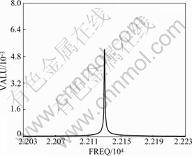
Fig.3 Swing simulation without damping
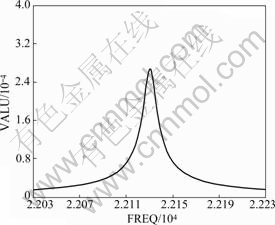
Fig.4 Swing simulation with damping
2.2 Element type selection
After generating the model, element types are set in the ANSYS pre-processor. Each element has its own features. Selection of suitable element types according to material and design of the ultrasonic vibrating system were made to ensure the analytical correctness. The ultrasonic vibrating system is predominantly divided into metallic materials and the piezoelectric ceramics. Element selection varies due to differing features. The metallic materials contain iron, phosphor bronze, and aluminum alloy. Consideration for the special curved surface structure of the vibrating system was given, and solid 92, a tetrahedron with 10 nodes was selected as the element. As the tetrahedron element allows the finite element analysis software to grid a complex geometric model easily, it is suitable for the shape requirement of the vibrating systems.
2.3 Material properties setting
The finite element analysis requires that materials are set individually. Only elastic modulus(Ex) and the Poisson ratio(υ) are requested for general structural analysis. However, dynamic analysis requires the general inertial force, to be calculated by converting volume into mass using the material density. Hence, the material density is also an input.
The material settings include those of both metallic materials and piezoelectric ceramics. The parameters for the metallic materials, stainless steel, phosphor bronze, titanium and aluminum alloy are listed in Table 1.
Table 1 Metallic material parameters

2.4 Element meshing setting
According to the basic principles of finite element analysis theory, the smaller the mesh element size is, the more accurate the results of an analysis will be. If the mesh element size is infinitely small, the theoretical model will approach the optimal solution. However, this is only a presumption. In the analysis process, when used elements are too small, element meshing will generate too many elements, nodes and freedom for the model in general. This increases computational intensity, resulting in a model that is either too time-consuming to solve, or potential errors in values. Thus, reasonable mesh element size is a factor that shall be considered in the analysis.
2.5 Boundary condition setting
After finalizing settings for the ANSYS pre-processor, boundary conditions must be set in the solution-finding processor. The piezoelectric ceramics used in this study can take 1 kV. Taking into consideration of demand and durability, it was decided that a 500 V power input would be used in the simulation. The two outer ends of the piezoelectric ceramics are connected to the ground output (i.e. with input voltage at 0). In the situation of fixed ends, all the degrees of freedom at the fixed end of the horn are set as 0, as shown in Fig.5.
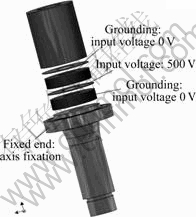
Fig.5 Boundary condition setting
3 Vibrating system design and analysis
The simulation of the ultrasonic vibrating system is conducted by ANSYS. After material constants, piezoelectric parameters and boundary conditions are input into ANSYS, the analysis and solution finding processes are started. The principle is to input an AC current of high frequency into the oscillator, to be converted to high speed repetitive mechanic vibrating movement, thus simulating the swing and structure pressure distribution at the working frequency.
3.1 Oscillator design
The oscillator design determines the vibrating power transfer efficiency. When designing the oscillator, in addition to considering the requested output power, the maximum output power that the materials used can bear should be confirmed to ensure smooth ultrasonic transfer and minimize energy waste. The geometric design is focused on ensuring maximum power and ease of production. The most important part of an oscillator is the horn. A well-designed horn not only smoothly transfers and amplifies ultrasonic power, but also reduces the occurrence of pressure concentrations as shown in Fig.6. The design of a ring-shaped groove at the oscillator node can avoid damage caused by slip from the node in action and effectively absorbs redundant vibrating power. This ensures that the oscillator smoothly transfers vibrating power and prevents damage caused by heat production.
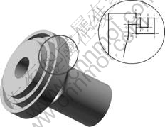
Fig.6 Fixed end design of horn
3.1.1 Material selection
In addition to the piezoelectric ceramics, the oscillator used in this study is made of a large number of metallic materials such as stainless steel for the interior filling plate, and titanium alloy for the horn. The major considerations for metallic material selection include whether their material properties aid in power transfer, how difficult they are to manufacture and how available
the material is.
3.1.2 Geometric shape
Shapes of horn, such as the uniform cross-section ladder, conical, exponential and the Fourier types are shown in Fig.7. Each has advantages and disadvantages. However, they do not differ greatly in amplification degree when also considering performance and manufacturing ease. Hence, in this study the ladder- shaped type was selected.
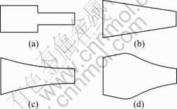
Fig.7 Types of horns: (a) Uniform cross-section ladder-shaped; (b) Conical shaped; (c) Index shaped; (d) Fourier
3.2 Milling tool design
3.2.1 Vibration transformation theory
In various processing procedures, tools have an impact on the processing accuracy. This is also an important factor during ultrasonic transfer in the ultrasonic processing system. To apply the vertical power generated by an ultrasonic device during milling, the power generated has to be transformed by tools from a vertical wave to a horizontal wave, as shown in Fig.8. Only then, can ultrasonic power be fully applied during the milling process. The way of accomplishing the vibration transformation is to set the vibration transformation at the point of largest pressure (namely, the vibration node) in conjunction with the lateral vibrating device, in order to output the horizontal wave in the direction of lateral.
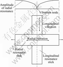
Fig.8 Conversion of vibration energy
Consideration should be given to the ultrasonic transfer rate and tool durability during the milling tool design. The ultrasonic transfer rate and vibration trans-formation theory are applied to designing the transformation of lateral power. Durability must be given consideration that the maximum transformer rate shall be compromised with the lowering of pressure concentration. Adjustments to the tool design shall be made according to the process in which the tool is applied. Considerations of material hardness, processing resistance, processing scope and the required surface accuracy shall be taken to make tool adjustments in accordance with design requirements. The key points of the tool design include tool frequency, pressure distribution, swing and vibrating power transfer efficiency. As the modeling adopted for the ultrasonic vibrating system in the present study is rather complicated, the finite element analysis is thus employed to allow analysis using power pressure to drive the ultrasonic vibrating system to simulate its dynamic reactions. Data regarding the swing, pressure distribution and working frequency of the tool can be obtained, in order to simplify the design process, saving design time and increasing design accuracy.
3.2.2 Tool shape design
As this study is focused on ultrasonic milling for analysis and experimentation, the lateral vibrating power transformation efficiency has been considered during tool shape design. The practical performance is not accurate when only the milling process is investigated, by integrating tool shape with the ultrasonic vertical vibrating power, as shown in Fig.9; and the durability of the tool is relatively poor. Such processing is more suitable for vertical processing procedures such as drilling and screwing. Hence, we designed and analyzed vertical and lateral power transformation using experiments to test the tool vibrating power transformation efficiency.
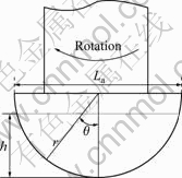
Fig.9 Hemispherical milling tool
3.3 Observations of vibrating system analysis
Development and manufacturing costs can be reduced by use of ultrasonic vibrating system analysis, eliminating the use of any trial and error methods. Although equations can be applied to calculating and designing for traditional manufacturing methods, many details cannot be considered, leading to poorer design performance in the vibrating system than expected, for unknown reasons. By using the finite element analysis software during system design, the analysis results indicate whether swing, working frequency and pressure distribution results can be checked for compliance with design requirements, adjustments can be made immediately if necessary.
3.3.1 Ultrasonic transfer performance
The issue of transfer performance is considered at the beginning of tool design. As such, various tools were designed and developed according to vibration transformation theory for mode and simple harmonic analysis in ANSYS, which enabled retrieval of data regarding swing, working frequency, and pressure distribution. For many variables, such as tool fastening force, geometric measurement errors exist in practical processing. Therefore, the ultrasonic oscillator simulation results shall be compared with the real measured swing and working frequency to assess the transfer performance in practice.
3.3.2 Pressure distribution and damage assessment
Pressure distribution is a factor of consideration in the tool design process. Because ultrasonic power is a continuous high-frequency vibrating power, pressure analysis should be conducted in order to avoid the amplification of swing and pressure at resonance points, which may lead to damage to the oscillator or the tool due to discontinuous power transfer.
To obtain the pressure distribution in order to assess the damage possibility, the present study adopts finite element analysis software to conduct an analysis of the ultrasonic vibrating system. Since the ultrasonic vibrating system contains various types of materials, such as titanium alloy, stainless steel, phosphor bronze and piezoelectric ceramics, metallic parameters and piezoelectric parameters should be corrected before inputting into ANSYS. This will reduce analysis errors and further improve the accuracy of the power pressure distribution. The pressure distribution shall also be considered during the design process, as theoretically, infinite amplification at resonance points of swing and pressure can occur due to the high frequency ultrasonic power. If the pressure is not transferred in a continuous manner, it may result in pressure concentration, leading to damage at sections of high pressure concentration, which may damage or break the tool during processing. Damage assessment is necessary in order to prevent such occurrences.
4 Simulation results and analysis
.igure In regard to the processing of hard and brittle materials during processes such as drilling, milling, and cutting, traditional methods are workable; however, they may increase required time and costs. Ultrasonic vibration processing can greatly reduce processing time as well as lengthen the tool service life. Fig.10 illustrates grinding wheel vibration directions. The arrows indicate the lateral and vertical vibration directions concurrently. Fig.11 illustrates the total displacement distribution volume.
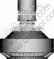
Fig.10 Grinding wheel vibration direction
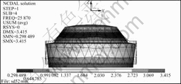
Fig.11 Total deformation distribution volume
5 Experimental parameters and planning
5.1 Parameter planning
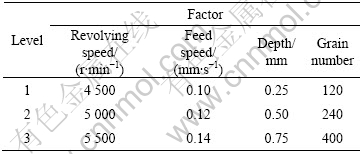
Parameter planning includes four factors: revolving speed (r/min), feed speed (mm/s), depth (mm) and grains number for adjustment. Originally, the ultrasonic swing was regarded as a factor. However, it is found after experimentation that it is not easy to measure the unstable swing value during the experiment process due to the processing static pressure, which is related to progressing speed and processing depth. The parameter planning of this study was conducted using Taguchi method with 4 factors at 3 levels as shown in Table 2.
Table 2 Parameter planning
5.2 Experiment planning
The easy availability of glass materials made them ideal as the experimental workpieces for testing the tool milling performance. Milling experiments were conducted on the glass work pieces by use of the lateral vibrating power that was transformed from the revolving main axis of the ultrasonic processing machine using the designed milling tool, a diamond grinding wheel. The results were used to determine whether ultrasonic power helps to promote milling efficiency.
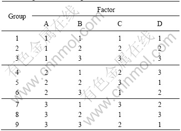
The Taguchi experiment planning method was applied in the experiment to reduce the waste of materials and time. Using four factors at three levels, the experimental design can best meet the requirements of this experiment and effectively control the use of materials and factor performances. Table 3 shows the Taguchi method L9(34) diagram of the present study.
Table 3 Taguchi method diagram
5.3 Experimental results, observations and discussion
The ability of the main axis motor power to match with the designed milling tool was not considered during parameter planning. It was found, after the experiment started, the motor revolving speed suddenly dropped, and even stopped in depths greater than 1 mm, leading to damage due to overheating. This arose because of the relatively large processing area of the milling tool and the increase in contact area as processing depth increased, leading to an increase in resistance. Either the main axis motor had to be replaced or the processing depth was lowered in order to compensate for this effect. It is difficult to replace the main axis motor. The experimental objective is to observe the milling process performance, which does not require reaching a particular depth. Therefore, the processing depth was lowered to less than 0.75 mm.
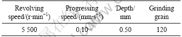
The difference by addition of ultrasonic power was highly apparent from the comparison experiment. The diamond grain grinding wheel of thickest coarseness was applied in this study (120). The parameters are shown in Table 4. When no ultrasonic power was utilized, the milling process failed, as the motor stopped due to large milling resistance. This arose even though the coarsest grinding grain and a relatively slow progressing speed were applied. When the same experimental parameters were used with ultrasonic power, the processing was accomplished smoothly. When using the same experimental parameters, with grinding wheel No. 400 and ultrasonic power, the milling was also accomplished.
Table 4 Ultrasonic comparative group-experimental parameters
6 Conclusions
On the premise of leaving the ultrasonic vibrating system framework unaltered, to promote the application of ultrasonic power in increasing milling process performance, the lateral material removal requirements of the milling process cannot be satisfied if only changes to the tool shape are made to increase the lateral directional force. To increase the material removal efficiency, this study applies vibration transformation theory to transform the ultrasonic vertical power into lateral power at the vibration node. It also enabled design tools more suitable for milling processes to be designed. The expansion and contraction of tool at the processing section after power transformation are fully incorporated, and used to effectively improve the milling performance. The following conclusions are drawn:
1) A feature of the milling process is the requirement for a large horizontal cutting force, while the most suitable aspect of the ultrasonic processing system to the milling process is its vertical vibration. After transforming the vertical vibration power into lateral vibration, the horizontal cutting force can be effectively increased. However, slight vertical vibration still exists, which aids in material removal.
2) To increase the vibrating system swing, the swing amplification shaft can be used to amplify the requested swing in addition to increasing the input power pressure. After modeling the designed amplification shaft in ANSYS for simulation analysis, the amplified values were shown to be linear with the theoretical ones.
3) The finite element analysis software to simulate the vibration reaction in the ultrasonic vibrating system was used in conjunction with proper element coupling, general metallic materials and piezoelectric ceramics, and was shown to have very high accuracy. This will enable design time and manufacturing costs to be effectively reduced in practical manufacturing.
References
[1] SEAH K H W, WONG Y S, LEE L C. Design of tool holders for ultrasonic machining using FEM [J]. Journal of Material Processing Technology, 1993, 37: 801-816.
[3] SHERRIT S, DOLGIN B P, BAR-COHEN Y, PAL D, KROH J, PETERSON T. Modeling of horns for sonic/ultrasonic applications [C]// IEEE Ultrasonic Symposium 1999. Caesars Tahoe NV, USA, 1999: 647-651.
[4] AMIN S G, AHMED M H M, YOUSSEF H A. Computer-aided design of acoustic horns for ultrasonic machining using finite-element analysis [J]. Journal of Material Processing Technology, 1995, 55: 254-260.
Corresponding author: Kei-Lin KUO; Tel: +886-2-27712171-3623; E-mail: klkuo@ntut.edu.cn
(Edited by YANG Bing)

