Trans. Nonferrous Met. Soc. China 25(2015) 3252-3257
Preparation of lead-free free-cutting graphite brasses by graphitization of cementite
Hai-ou ZHUO, Jian-cheng TANG, Ying-yu XUE, Nan YE
School of Materials Science and Engineering, Nanchang University, Nanchang 330031, China
Received 17 November 2014; accepted 10 March 2015
Abstract: Graphite brasses were prepared by graphitizing annealing of cast brasses containing cementite particles, which were in-situ formed during the fasting process. The eutectic cast iron as carbon source was added into common brasses by casting. SEM and EDS were used to analyze the microstructure of graphite brasses, and the relationship between the microstructure and machinability was investigated. The results show that graphite particles are formed by the decomposition of cementite particles in cast brasses. The graphite particles are uniformly dispersed in the brass matrix with the average size of 5.0 ��m and the volume fraction of ~1.1%. The machinability in the graphite brass is dramatically increased relative to the common brass, because of the lubricating properties of graphite particles and its role in chip breaking. The workpiece surface of the graphite brasses chips is smooth and burr-free, and the chips of graphite brasses are short (C-shape) and discontinuous, which is much better than that of the long spiral chips of common brasses.
Key words: lead-free graphite brass; graphitization annealing; microstructure; machinability
1 Introduction
Lead brass, as an important fixture material, is widely used in many applications, such as lock parts, toys, watches and plumbing fixture, owing to its excellent corrosion resistance, good castability and visual appearance, and, most of all, outstanding machinability [1,2]. However, the natural leaching of lead from the lead brass fixtures can seriously pollute environment and harm to human health. Environmental Protection Agency (EPA) regulations suggest that the total lead discharge into potable water from all sources should not exceed 15��10-9, and the legal of many countries acts arose forcing fixture manufacturers to eliminate lead brasses from the fixture production [3]. Therefore, developing lead-free free-cutting brass materials has become a necessary and significant research focus.
Lead-free brass is designed by adding free- machining additives into Cu�CZn alloy instead of lead. These additives can generate brittle particles in brass matrix and promote the machinability by breaking chips and decreasing friction coefficient, playing the role of lead particles [4]. Until now, the most important additive is bismuth because it is more effective in chip segmentation than lead [5,6]. However, bismuth can lead to badly intergranular failure because of its intrinsically brittle and grain-boundary segregation. Moreover, as a rare resource, the cost of free-cutting brasses will be drastically increased due to the use of bismuth. What is more, many studies show that bismuth is only slightly less harmful to human than lead, but not non-harmful [2]. Graphite, having a hexagonal-layered structure and lubricating properties, is believed to be an attractive candidate substituting for lead [7]. The major hindrances of developing graphite brasses are the large difference in the density between graphite and copper, and the non-wetting characteristics. Although some special casting and powder metallurgy (PM) methods have been used to prepare the graphite brass, it is still difficult to achieve homogeneous distribution of graphite particles due to the non-wetting effect [8]. Beyond that, several elements, such as Ti, Si and Mg, were added into brass melt for increasing the solubility of carbon. But the generation of hard carbide particles causes undue tool wear, unfavorable for surface finish [9,10].
Carbon exists in iron and steel in the form of cementite, and these cementite particles are decomposed into graphite particles by the graphitization after heat treatment. Based on the fact above, in this work, we added cast iron into the brass instead of other form of carbon, and the cementite particles were in-situ formed during the casting process, then annealing treatment was conducted to facilitate the graphitization of cementite particles, and finally Cu�CZn�CFe�CC alloys with uniformly dispersed graphite particles were obtained. The solidification and graphitization annealing processes and the machinability were studied.
2 Experimental
Experimentally, Cu-40Zn with addition of 5% (mass fraction) eutectic cast iron (carbon content 4.3%) was prepared using a casting process, in which the nominal composition was Cu-38Zn-4.78Fe-0.22C. Pure copper and cast iron were induction-melted at over 1673 K, and pure zinc was added into the molten alloy at 1273 K, followed by casting the rods with 50 mm in diameter. The as-cast rods were extruded by a hydraulic press machine (2000 kN, SHP-200-450) under an extrusion ratio of 11. Subsequently, the extruded rod was annealed at 1073-1223 K for 1-2 h under inert gases protection.
The microstructures and composition of the as-cast and annealed samples were studied using scanning electron microscopy (SEM, FEI Quanta 200F), installed with energy-dispersive spectroscopy (EDS, Microlab MK II). Before SEM observation, the specimens were etched by ferric chloride hydrochloric solution (5 g FeCl3 + 25 mL HCl + 100 mL H2O). The X-ray diffraction (XRD) with Cu K�� radiation source was used to obtain diffraction patterns. Turning experiments were operated on a CA6136 machine tool. The cutting parameters were as follows: cutting speed vc=35 m/min, feed f=0.1 mm, depth of cut ap=0.5 mm, rake angle ��=15��, entering angle 62.5��, high-speed tool steel W18Cr4V, and no cutting fluid. The surface of the brass workpiece was observed by optical microscopy (OM, MeF3).
3 Results and discussion
3.1 Microstructure
The microstructures of the as-cast and annealed brass materials are shown in Figs. 1(a) and (b), respectively. The matrix of the as-cast specimen consists of two phases �� and ��, in which convex ��-phase is embedded on the concave ��-phase background, which is the typical characteristic for this group of alloys. The shape of ��-phase with a volume fraction of ~15% is strip-like and irregular. The bright particles with a size of ~3 ��m are uniformly distributed in the brass matrix. Both ��-phase and ��-phase are observed. Before annealing the cast ingot was extruded under an extrusion ratio of 11. The flaws formed during the deformation process can promote the diffusion of iron atom and the decomposition of cementite, and accelerate the graphitization progress. Figure 1(b) displays the SEM image of the annealed sample. It can be clearly seen that the changes in microstructure are pronounced. The grain size and the volume fraction of ��-phase (convex grain) substantially increase, which becomes the major phase of the annealed matrix. The volume fraction of ��-phase may be up to ~80%, while that is ~15% in the as-cast sample, which can be assigned to the transition from ��-phase to ��+�� duplex phase during the heat treatment [11,12]. The spherical particles with a mean size of 5 ��m and volume fraction of ~1.1% are homogeneously distributed in the annealed matrix, whose morphologies are similar to those in the normal cast alloys. In order to determine the chemical composition of these particles, SEM�CEDS point analysis was conducted. The analysis results of the EDS are shown in Figs. 1(c)-(f). In the as-cast specimen, some Fe elements dissolve in the brass matrix and others constitute cementite (the bright particles in Fig. 1(a)). However, in the annealed brass, the particles are composed of carbon elements, and the content of Fe dissolved in matrix increases. Based on these observations, it can be inferred that the particles transform from cementite to graphite by the graphitization after heat treatment.
The XRD analysis results for the cast and annealed alloys are shown in Fig. 2. The as-cast and annealed specimens exhibit high peak intensity due to the ��-phase at 43.5�� with a (110) crystal plane and the ��-phase at 42.3�� with a (111) crystal plane, respectively. The peaks of graphite are found at 27.4�� and 77.0�� in annealed specimen. The volume fractions of ��-phase in the cast and annealed specimens are 19% and 82%, respectively, as calculated from the diffraction intensity ratios of the ��-phase (111) to the ��-phase (110) in the XRD patterns. This indicates the phase transformation from �� to ��+�� duplex phase after annealing and furnace cooling. These results are in agreement with the SEM observations shown in Fig. 1.
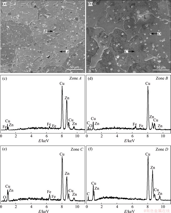
Fig. 1 SEM images of as-cast (a) and annealed (b) brasses and EDS analysis results (c-f)
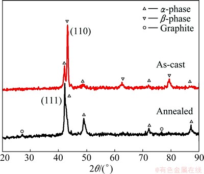
Fig. 2 XRD patterns of as-cast and annealed brasses
The schematic diagrams of the solidification and annealing processes are illustrated in Fig. 3, which include the processes of both in-situ forming and the graphitization of cementite. Because of higher supercooling of carbon, in the solidification process of Cu-Zn-Fe-C alloy melts, C elements crystallize firstly in the form of graphite or cementite. Graphite is more stable than cementite due to its lower free energy. However, the difference in carbon content between cementite (6.69%) and the Cu-Zn-Fe-C melts (0.22%) is much smaller than that between graphite (100%) and the melts. Moreover, the lattice structure of cementite is more similar to the short range order atomic group in melts than that of graphite. Therefore, graphite can be formed more easily in terms of the thermodynamics, while cementite in terms of the kinetics. Cooling rate plays a key role in the final form of carbon elements. Cementite particles are formed more easily in the process of rapid cooling, while slow cooling is more likely to cause the formation of graphite. Graphite particles would float on the alloy melts due to their lower density, which leads to lower carbon content in brasses. When Cu-Zn-Fe-C alloy melts are poured into the cold iron mould under the rapid cooling condition, the cementite particles precipitate firstly, and then the melts solidify with the decrease of temperature. In addition, the cementite particles can act as nucleators, which can further promote the solidification of the melts, as indicated in Figs. 3(a)-(d). At about 1023 K, a solid phase transition of �¡���+�� starts [13,14]; however, this transition is incomplete because of the rapid falling of temperature during the solidification. As a result, the as-cast microstructures are mainly �� phase, a few �� phase and dispersed Fe3C phase (particles), as schematically depicted in Fig. 3(e). The as-cast specimen is graphitization annealing treated at 1073-1223 K for 1-2 h, and then furnace-cooled to room temperature. The �¡���+�� and Fe3C��Fe+C transitions can be finished, and consequently, the volume fraction of ��-phase increases significantly after annealing. Due to the extremely low solubility and slow diffusion velocity of carbon in brass matrix, the graphite particles do not coarsen drastically, though the graphitization is a process of volume expansion.
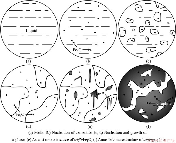
Fig. 3 Schematic diagrams of solidification and annealing
3.2 Machinability
The chip shape is a very important factor to evaluate the machinability because it describes the possibility of using automatic machining processes. Discontinuous chips are a desired characteristic of free-machining alloys and are preferred for their ease of automatic disposal. Greater degree of automation over the years has made this aspect of machinability become increasingly important [15]. Typical chips of the lead brass (C3604, extrusion), common brass (Cu�C40Zn), and annealed graphite brass obtained by turning operation test are shown in Figs. 4(a), (b) and (c), respectively. The discrete needle-shaped chips of C3604 alloy suggest that the intrinsic brittleness of Pb leads to the breaking behavior of chips. ISLER et al [16] classified the curled chips as short (0-3 spiral), medium (3-6 spiral), and long chips (6 spiral). Therefore, the chips of C3604 alloy are ��short�� according to this classification. The chips of the graphite brass show a discontinuous arc shape (Fig. 4(c)). Graphite has a hexagonal-layered structure and lubricating properties, which may contribute to the machinability by lowering the shear ductility of the alloy. These features can help to break up chips on the primary shear plane and reduce the power requirement for machining. It should be pointed out that the chip size of the graphite brass is larger than that of the lead brass. This may be attributed to different microstructures. The annealed graphite brass has a coarse-grained two-phase microstructure, while a fine microstructure is reported in the extruded C3604 alloy, which improves the ability of breaking swarf [17]. Compared with the chips of C3604 alloy, the larger ones of graphite brass may be classified to the ��short�� type because most of them only have one spiral. These chips are easy to remove and would not wind up on cutting tool. The chips of common brass, however, show a continuous spiral shape, as shown in Fig. 4(b). These snarl chips are difficult to be disposed, which may wind up on cutting tool and drastically affect the surface quality and tool life.

Fig. 4 Chip morphologies of lead brass (a), common brass (b) and graphite brass (c)
From a machinability standpoint, surface quality is of a prime consideration in a finishing operation [18]. Optical microscopy photograph of the workpiece surface is shown in Fig. 5(a). It can be seen that the surface texture is typical peak-to-valley induced on the workpiece by the high speed turning. Both graphite brass (Fig. 5(c)) and lead brass (Fig. 5(a)) show a significant improvement of the surface finish, compared with the common brass (Fig. 5(b)). The machining tracks of graphite brass workpiece are very small and apparently shallow. Graphite or Pb particles as a lubricant added into brasses can spread out and cover the tool-chip surface, and decrease the friction coefficient [3]. Furthermore, graphite, due to its hexagonal-layered structure, is more effective in lubrication action than lead [8,19]. Such an effect can be confirmed by the insets in Figs. 5(a)�C(c). The surface photograph of the graphite brass approaches to a desired appearance, and the high speed turning stripes almost cannot be seen.
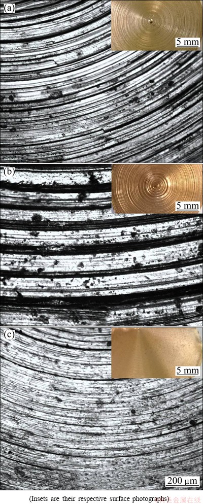
Fig. 5 Surface morphologies of lead brass (a), common brass (b) and graphite brass (c)
4 Conclusions
1) The addition of graphite by the graphitization of cementite is feasible. The cementite particles are in-situ formed firstly during the casting process, and then annealing treatment is conducted to facilitate the graphitization of cementite. It is important and interesting that graphite brasses with uniformly dispersed precipitates are successfully obtained.
2) The addition of graphite significantly improves the machinability of brass materials by promoting chip segmentation and lubrication action. The turning process is steady and the cutting force is stable. The graphite brass shows comparable machinability to conventional lead brass.
References
[1] BURSIKOVA V, BURSIK J, NAVRATIL V, MILICKA K. Creep behaviour of leaded brass [J]. Materials Science and Engineering A, 2002, 324: 235-238.
[2] SUN Z M, HASHIMOTO H, BARSOUM M W. On the effect of environment on spontaneous growth of lead whiskers from commercial brasses at room temperature [J]. Acta Materialia, 2007, 55(10): 3387-3396.
[3] KUYUCAK S, SAHOO M. A review of the machinability of copper-base alloys [J]. Canadian Metallurgical Quarterly, 1996, 35(1): 1-15.
[4] la FONTAINE A, KEAST V J. Compositional distributions in classical and lead-free brasses [J]. Materials Characterization, 2006, 57(4): 424-429.
[5] JANG Y, KIM S, HAN S. Effect of misch metal on elevated temperature tensile ductility of the Cu-Zn-Bi alloy [J]. Metallurgical and Materials Transactions A, 2005, 36(4): 1060-1065.
[6] ATSUMI H, IMAI H, LI S, KONDOH K, KOUSAKA Y, KOJIMA A. High-strength, lead-free machinable ��-�� duplex phase brass Cu-40Zn-Cr-Fe-Sn-Bi alloys [J]. Materials Science and Engineering A, 2011, 529: 275-281.
[7] ROHATGI P K, NATH D, KIM J K, AGRAWAL A N. Corrosion and dealloying of cast lead-free copper alloy�Cgraphite composites [J]. Corrosion Science, 2000, 42(9): 1553-1571.
[8] KIM J K, ROHATGI P K, CHOI J O, CHOI C O. Wear properties and effect of molds on microstructure of graphite reinforced copper alloy composites made by centrifugal casting [J]. Metals and Materials International, 2005, 11(4): 333-340.
[9] HUANG J S, PENG C Q, ZHANG S Q, HUANG B Y, MA C S. Microstructure and properties of cutting magnesium-brass containing no lead [J]. Transactions of Nonferrous Metals Society of China, 2005, 15(6): 1242-1247.
[10] LI S, IMAI H, ATSUMI H, KONDOH K, KOJIMA A, KOSAKA Y, YAMAMOTO K, TAKAHASHI M. The effects of Ti and Sn alloying elements on precipitation strengthened Cu40Zn brass using powder metallurgy and hot extrusion [J]. Materials Science and Engineering A, 2012, 535: 22-31.
[11] LIU Zeng-cai, LIN Le-yun, LIU Shao-feng, ZHAO Yue-hong. Diffusion mechanism of dezincification in double-phase brass exposed to sea water [J]. Transactions of Nonferrous Metals Society of China, 1999, 9(3): 572-577.
[12] MAPELLI C, VENTURINI R. Dependence of the mechanical properties of an ��/�� brass on the microstructural features induced by hot extrusion [J]. Scripta Materialia, 2006, 54(6): 1169-1173.
[13] PADMAVARDHANI D, PRASAD Y. Characterization of hot deformation behavior of brasses using processing maps. Part I: �� brass [J]. Metallurgical Transactions A, 1991, 22(12): 2985-2992.
[14] GOUKON N, IKEDA T, KAJIHARA M. Growth behavior of fine grains formed by diffusion induced recrystallization in the Cu (Zn) system [J]. Acta Materialia, 2000, 48(11): 2959-2968.
[15] BYRNE G, DORNFELD D, DENKENA B. Advancing cutting technology [J]. CIRP Annals��Manufacturing Technology, 2003, 52(2): 483-507.
[16] ISLER P, BARBEZAT G, FORM W. New chip-length index [J]. Metals Materials, 1971, 5(8): 265-266.
[17] HOFMANN U, EL-MAGD E. Behaviour of Cu-Zn alloys in high speed shear tests and in chip formation processes [J]. Materials Science and Engineering A, 2005, 395(1): 129-140.
[18] BARLETTA M, GUARINO S. High speed finishing of a CuZn15 brass alloy by abrasive recirculating fluidized bed (ARFB) [J]. Powder Technology, 2010, 203(3): 591-602.
[19] KESTURSATYA M, KIM J K, ROHATGI P K. Wear performance of copper�Cgraphite composite and a leaded copper alloy [J]. Materials Science and Engineering A, 2003, 339(1): 150-158.
��̼��ʯī���Ʊ���Ǧ������ʯī��ͭ
��Ÿ���ƽ��ɣ�Ѧ��楣�Ҷ �
�ϲ���ѧ ���Ͽ�ѧ�빤��ѧԺ���ϲ� 330031
ժ Ҫ��ͨ�����ͭ�����ӹ���������������������ԭλ������̼�����������ʯī���˻���ʹ��̼��ֽ��ʯī�Ӷ��Ƶ�ʯī��ͭ������SEM��EDS����ʯī��ͭ������֯, ̽������֯���������ܵĹ�ϵ�������������̬��ͭ�е���̼����������˻��ȫ���ֽ�Ϊʯī������ʯī����������ɢ�طֲ��ڻ�ͭ�����ϣ���ƽ���ߴ�Ϊ5.0 ��m���������ԼΪ1.1%��ʯī��ͭ�ij�������⻬��ë�̣���м��òΪ��C�ͣ���Ǧ��ͭ�Ĵִ�������ͨ��ͭ�ij�������м��
�ؼ��ʣ���Ǧʯī��ͭ��ʯī���˻�����֯����������
(Edited by Wei-ping CHEN)
Foundation item: Projects (51271090, 51364036, 51471083) supported by the National Natural Science Foundation of China; Project (IRT0730) supported by the Program for Changjiang Scholars and Innovative Research Team in University, China; Project (NCET-10-0184) supported by the Program for New Century Excellent Talents in University, China; Project (20103601110001) supported by the Specialized Research Fund for the Doctoral Program of Higher Education of China
Corresponding author: Jian-cheng TANG; Tel: +86-791-83969559; E-mail: tangjiancheng@ncu.edu.cn
DOI: 10.1016/S1003-6326(15)63961-9

