J. Cent. South Univ. Technol. (2010) 17: 332-339
DOI: 10.1007/s11771-010-0050-2 
A new semi-active suspension control strategy through mixed H2/H�� robust technique
ZHENG Ling(֣��), LI Yi-nong(����ũ), CHEN Bing-kui(�±���)
State Key Laboratory of Mechanical Transmission, Chongqing University, Chongqing 400044, China
? Central South University Press and Springer-Verlag Berlin Heidelberg 2010
Abstract: A new semi-active suspension control strategy through mixed H2/H�� robust technique was developed due to its flexibility and robustness to model uncertainties. A full car model with seven degrees of freedom was established to demonstrate the effectiveness of the new control approach. Magneto-rheological (MR) dampers were designed, manufactured and characterized as available semi-active actuators in the developed semi-active suspension system. The four independent mixed H2/H�� controllers were devised in order to perform a distributed semi-active control system in the vehicle by which the response velocity and reliability can be improved significantly. The performance of the proposed new approach was investigated in time and frequency domains. A good balance between vehicle��s comfort and road holding was achieved. An effective and practical control strategy for semi-active suspension system was thus obtained. This new approach exhibits some advantages in implementation, performance flexibility and robustness compared to existing methods.
Key words: mixed H2/H�� control; semi-active suspension; magneto-rheological (MR) damper; linear matrix inequality (LMI)
1 Introduction
Controlled suspension systems can provide good passenger isolation from road unevenness while keeping admissible road holding performance [1-3]. In the past decades, many significant researches can be found in this area. Skyhook control suits well to improve comfort but is limited to improve road holding [4-5]. The linear quadratic control can provide both comfort and road holding improvements but requires the full state measurement or estimate [6-7]. Linear time invariant (LTI) H�� control can achieve better results improving both comfort and road holding and ensuring a defined frequency behaviour but is limited to fixed performances due to the fixed weights. Mixed LTI H��/H2 approaches can achieve a good balance between comfort and road holding [8-10]. Recently, linear parameter varying (LPV) approaches can either adapt the performances according to measured signals or improve robustness [11].
However, most of these controllers are designed and validated assuming that the actuator of the suspension system is fully active. Unfortunately, such active actuators are not used in a wide range yet because of their inherent cost and low performance. Therefore, semi-active actuators are often preferred [12-15]. In 2004, DELPHI used a kind of new semi-active actuators (called Magneto-rheological damper) to construct the industry��s first semi-active suspension technology with no electromechanical valves and no small moving parts [16]. It is now commercially available in several vehicle platforms such as Cadillac Seville STS, Chevrolet Corvette, and Cadillac Seville.
On the other hand, most of the work is focused on controlling vehicle vertical dynamics of quarter car model or half-car model. Only a few people researched the method to control vehicle dynamics of full-car model.
The contribution of this paper is to propose a controller for semi-active suspension system with MR dampers. In order to realize the global control for full-car model and ensure rapid response and reliability, a distributed control system including four independent controllers was presented. Mixed H��/H2 controllers were designed through robust control theory to reach a good balance between comfort and road holding, and ensure internal stability and robustness. As an important semi-actuator, MR damper was designed and manufactured. The property of MR damper was investigated and characterized to construct a closed loop control system for semi-active suspension with MR dampers.
2 Full-car model
A full-car model is constructed in Fig.1, where Ms is the sprung mass;  and
and  are the roll and pitch moments of inertia, respectively; ksi (i=1, 2, 3, 4) is the total stiffness coefficient of each suspension; csi (i=1, 2, 3, 4) is the damping coefficient of each suspension; kti (i=1, 2, 3, 4) is the stiffness coefficient of each tire; xc, �� and �� represent the vertical displacement, roll and pitch angular displacements, respectively. lxf and lxr are the distances between the front suspension and center of gravity of sprung mass (C.G.) and the rear suspension and C.G respectively; lylf and lylr are a half of front and rear wheel tracks; xsi, xti and wi are the displacements of the sprung, unsprung masses, and the disturbance applied to the ith tire, respectively.

Fig.1 Full car dynamic model with seven degrees of freedom
Several vectors are defined in order to describe the full car dynamics in state space form:
 ,
, 
 ,
,

The relative position vector of each suspension can be denoted:

Let H be the transformation matrix relating the body motion vector XC to the corner position vector xs:
 (1)
(1)
H can be calculated using vehicle geometry parameters as follows:

Let F be the total suspension force vector, which can be approximated as a linear function of the relative position vector xst, the relative velocity vector and the active control force u:
 (2)
(2)
where


The sign (diag) represents diagonal matrix. The equation of motion for the car body can be expressed as
 (3)
(3)
Let , Eq.(3) can be expressed in matrix form:
 (4)
(4)
The motion equations of wheels can also be written as:
 (5)
(5)
where


Substituting Eq.(2) into Eqs.(4)-(5) leads to the following linearized vertical dynamics:
 (6)
(6)
Let  , Eq.(6) can be rewritten as
 (7)
(7)
 ,
,  ,
,  ,
,  , and E2=
  .
.
Define  , Eq.(7) can be expressed in state space form:
 (8)
(8)
where
 ,
,  , B2=
, B2=  .
.
The state space Eq.(8) is used to design mixed H2/H�� controller of semi-active suspension system with MR dampers.
3 MR damper
A prototype MR damper with the mixed mode was designed and manufactured in order to perform semi-active suspension system in the vehicle. The configuration of the MR damper is shown in Fig.2. This is a twin-tube damper with the double-class magnetic circuits.

Fig.2 Configuration of MR damper
The damping force of the MR damper can be derived as follow [13-14]:

 (9)
(9)
where Ap is the working area of the piston; �� is the viscosity of the MR fluid without the magnetic field applied; l is the length of each damping duct; R2 is the inner radius of the inner housing, and R1 is the outer radius of the piston. Eq.(9) can be rewritten in a simple form:
 (10)
(10)
where

 is the piston velocity; Cs is the equivalent viscous damping coefficient; FMR is the controllable damping force; K and �� denote the characteristic constants of the MR fluid, which can be determined by magnetic properties from the experiment for the MR fluid. Here, the MR fluid is supplied by Chongqing Instrument Material Research Institute, China. K and �� are equal to 0.061 8 and 1.25.
The main geometrical and physical parameters of the MR damper are listed in Table 1, where N represents the number of coil and Dp is the piston diameter.
Table 1 Geometrical and physical parameters of MR damper

The prototype MR damper was tested using a servo- hydraulic shock testing dynamometer. It has a maximum stroke of 12.5 cm and is equipped with a 50 kN load cell that measures the damping forces of the shock absorber and a displacement transducer that measures its displacement. The maximum velocity is 2.5 m/s. Experimental data are collected to determine the performance of the unit as a function of input current and frequency. To activate the electromagnet, a direct current (DC) power supply was utilized. Experiments were conducted at a peak-to-peak amplitude of 25 mm, different frequencies and different input currents.
Fig.3 shows the theoretical and experimental results. It can also be seen that the theoretical predictions are in close agreement with the experimental results. This means that Eq.(10) can be used to describe the characteristics of the prototype MR damper and decide the real-time input current.

Fig.3 Comparison between theoretical and experimental characteristics of MR damper: (a) Force vs displacement; (b) Force vs velocity
4 Controller design
Generally speaking, the ride comfort and road holding capability are conflicting objectives. In order to simplify the control system of the full-car semi-active suspension with MR dampers, four independent H2/H�� optimal controllers are designed. Each controller is used to control one quarter of the full-car model. In this way, the computational burden for the whole control system can be reduced. It is called distributed control system. Usually, rapid response is an important factor to be considered in practical application. The distributed control system can improve the system response well. Fig.4 shows the control scheme for the distributed control system with four independent H2 /H�� optimal controllers. K(s) and G(s) represent transfer functions.
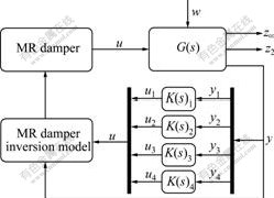
Fig.4 Control structure and scheme of distributed control system
A quarter vehicle dynamic model is used to design four multi-objective and mixed H2/H�� controllers. It is shown in Fig.5.

Fig.5 Scheme of a quarter vehicle dynamic model
The dynamic equations can be written by the Newton method:

(11)
where i=1, 2, 3 and 4 represents left-front, right-front, left-rear, right-rear suspension, respectively; and msi is sprung mass distributed by Ms at each corner.
Define state variables and output variables:
 (12)
(12)
Eq.(11) can be expressed in the state-space form:
 (13)
(13)
 (14)
(14)
An important problem is to reasonably choose performance variables to characterize vehicle comfort or road holding. The heave acceleration is one possible variable to measure the comfort performance, while the tire deflection derivative is the other possible variable to measure road holding due to the fact that the small tire deflection derivatives imply small variations of the tire deflections. Therefore, two important performance variables are defined:
 (15)
(15)
 (16)
(16)
Obviously, if the transfer function from wi to z��i and that from wi to z2i are denoted as T��i(s) and T2i(s), then the following performance measures may be used to characterize vehicle ride comfort and road holding respectively:
 ,
, 
where
 ,
,  .
.
According to the above analysis, the goal here is to find algorithm Ci with the following form
 (17)
(17)
to limit the peak frequency responses, which is measured by the H�� norm of the involved transfer matrix of the following variable:
 (18)
(18)
and the variance of the following variable with respect to unit covariance white noise disturbance :
:
 (19)
(19)
The latter is also equivalent to a quadratic criterion in frequency domain and is called a H2 norm criterion.
If the loop is closed by Cci to control the plant based on the sensor signal yi, then the closed-loop system can be expressed as:
 (20)
(20)
with


Our design objectives for mixed H2/H�� control are to minimize the following cost function fcf:
 (21)
(21)
The solutions for the above problem can be found by the linear matrix inequality solver (for example, LMI control toolbox associated with Matlab).
Numerical example
A numerical example is given to illustrate the effectiveness and advantage of the proposed new control approach. The vehicle parameters are summarized in Table 2.
Table 2 Vehicle parameters set in experiment

The control objective here is to compute the active control force ui such that the cost function defined in Eq.(20) is minimized for a fixed ��i. A series of the values of ��i are selected and the corresponding controllers are designed. These values of ��i are 10-5, 10-4, 10-2, 1/20, 1/10, 1, 5, 10, 30, 100, 1 000, respectively. The normalized H2 and H�� norms of  and
and  corresponding to front-left and rear-left quarter model are shown in Fig.6.
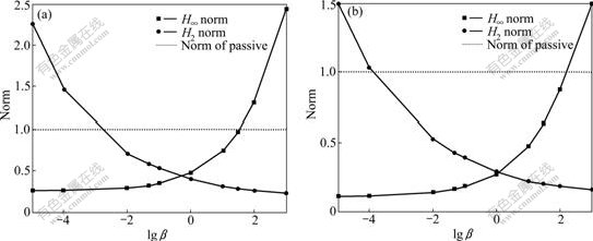
Fig.6 Normalized H2 and H�� norms of front-left suspension (a) and rear-left suspension (b)
It can be seen that increasing �� implies increasing the H�� norm and decreasing the H2 norm. A good balance point can be found in order to do well both in ride comfort and road holding. The optimal values of �� for the four independent controllers are determined through numerical simulation: ��1=1, ��2=1, ��3=5, ��4=5. The control force ui is calculated in an active manner.
However, the MR damper is a semi-active actuator. When the MR dampers are used as actuators in vehicle suspension systems, ui will become a semi-active control force. Therefore, a semi-active constrained condition should be applied:
 (22)
(22)
where i=1, 2, 3, 4.
A random signal from B-class road is used as road excitation where vehicle drives at 60 km/h.
Fig.7 demonstrates time responses with control or without control. It is noted that the body heave, roll, and pitch accelerations are reduced dramatically under control. This means that the ride comfort is improved obviously. On the other hand, it can also be seen that dynamic tire load on front-left is attenuated simultaneously. This implies that a good balance between the ride comfort and road holding can be achieved.

Fig.7 Time response to road input: (a) Heave acceleration; (b) Roll acceleration; (c) Pitch acceleration; (d) Dynamic tire load
Fig.8 shows the frequency responses to road input. Two peaks appear in the whole frequency range. The first one is located at the resonance frequency point for body, and the second is located at the resonance frequency point for wheel. Figs.8(a)-(c) demonstrate that the magnitude of the first peak is attenuated significantly by the proposed new controller. Fig.8(d) shows that the attenuation for the magnitude of the second peak is still effective and significant. A attenuation for both peaks identifies that a good balance between the ride comfort and the road holding can be achieved by the proposed H2/H�� controllers through the optimization of the weight coefficient ��. The mixed H2/H�� controllers are specially effective in frequency domain due to their design principle and objective. The new control approach can improve both the ride comfort and the road holding simultaneously, thus demonstrates the potential as an effective means for attenuating the vibration of vehicle suspension systems.

Fig.8 Frequency response to road inputs: (a) Heave acceleration; (b) Roll acceleration; (c) Pitch acceleration; (d) Dynamic load of tire
Fig.9 shows the field dependent damping force of the MR damper in the front-left suspension. The maximum damping force supplied by the MR damper in the front-left suspension is 600 N. The damping forces

Fig.9 Semi-active control force in front-left suspension
supplied by the other three dampers have the same order of magnitude. It is clear that damping force required can be reached by the MR damper designed in this paper.
6 Conclusions
(1) A full-car semi-active suspension system equipped with four MR dampers was developed. The MR dampers presented were designed, manufactured and characterized. They demonstrate a wide dynamic variation in damping force and are available semi-active actuators in vehicle suspension system.
(2) The full-car model developed can evaluate vehicle performances under control, which can be used as a platform to design semi-active controller and evaluate its effectiveness.
(3) The mixed H2/H�� controller based on multi- objective optimization can achieve a good balance between the ride comfort and the road holding, and finally attenuate vehicle vibration.
References
[1] FISCHER D, ISERMANN R. Mechatronic semi-active and active vehicle suspensions [J]. Control Engineering Practice, 2004, 12(11): 1353-1367.
[2] GIORGEOU G, VERROS G, NATSIAVAS S. Multi-objective optimization of quarter-car models with passive or semi-active suspension system [J]. Vehicle System Dynamics, 2007, 45(1): 77-92.
[3] IELUZZI M, TURCO P, MONTIGLIO M. Development of a heavy truck semi-active suspension control [J]. Control Engineering Practice, 2006, 14(3): 305-312.
[4] POUSSOT-VASSAL C, SENAME O, DUGARD L, RAMIREZ- MENDOZA R, FLORES L. Optimal skyhook control for semi-active suspensions [C]// Proceedings of the 4th IFAC Symposium on Mechatronics Systems. Berlin: Springer, 2006: 608-613.
[5] SAMMIER D, SENAME O, DUGARD L. Skyhook and H�� control of active vehicle suspensions [J]. Vehicle System Dynamics, 2003, 39(4): 279-308.
[6] HROVAT D. Survey of advanced suspension developments and related optimal control applications [J]. Automatica, 1997, 33(10): 1781-1817.
[7] WILLIAMS D, HADDAD W. Active suspension control to improve vehicle ride and handling [J]. Vehicle System Dynamics, 1997, 28(1): 1-24.
[8] LU J, DEPOYSTER M. Multiobjective optimal suspension control to achieve integrated ride and handling performance [J]. IEEE Transaction on Control System Technology, 2002, 10(6): 807-821.
[9] LU J. A frequency-adaptive multi-objective suspension control strategy [J]. ASME Journal of Dynamic Systems, Measurement and Control, 2004, 126(3): 700-707.
[10] TUAN H D, APKARIAN P, HOSOE S. Nonlinear H�� control for an integrated suspension system via parameterized linear matrix inequality characterizations [J]. IEEE Transaction on Control System Technology, 2001, 9(1): 175-185.
[11] ZIN A, SENAME D. Robust LPV/H�� control for active suspensions with performance adaptation in view of the global chassis control [J]. Vehicle System Dynamics, 2008, 46(10): 889-912.
[12] NAM Y J, PARK M K. Electromagnetic design of a magnetorheological damper [J]. Journal of Intelligent Material Systems and Structures, 2009, 20(1): 181-191.
[13] NGUYEN Q H, CHOI S B, WERELEY N M. Optimal design of magnetorheological valves via a finite element method considering control energy and a time constant [J]. Smart Material and Structure, 2008, 17: 1-12.
[14] UNSAL M, NIEZRECK C, CRANE C D. Multi-axis semi-active vibration control using magnetorheological technology [J]. Journal of Intelligent Material Systems and Structures, 2008, 19(12): 1463-1470.
[15] MAO M, HU W, CHOI Y T, WERELEY N M. A magnetorheological damper with bifold valves for shock and vibration mitigation [J]. Journal of Intelligent Material Systems and Structures, 2008, 18(12): 1227-1232.
[16] Delphi. Delphi magnerideTM [EB/OL]. [2010-03-10]. http://www. motor-talk.de/forum/action/Attachment. html?attackmentId=359392.
[17] ZHENG Ling, LI Yi-nong. Sliding model fuzzy control of semi-active suspension system with MR damper in vehicle [C]// Proceedings of the 10th International Conference Electro-rheological Fluids and Msgneto-rheological Suspension. Singapore: World Scientific Publisher, 2007: 487-495.
[18] LAN Wen-kui, ZHENG Ling. LI Yi-nong. Analysis of structure characteristics and magnetic field intensity for MR damper [C]// Proceedings of the 10th International Conference Electro-rheological Fluids and Msgneto-rheological Suspension, Singapore: World Scientific Publisher, 2007: 541-554.
Foundation item: Project(50775225) supported by the National Natural Science Foundation of China; Projects(CSTC, 2008AC6097, 2008BA6025) supported by National Natural Science Foundation of Chongqing, China
Received date: 2009-03-03; Accepted date: 2009-08-04
Corresponding author: ZHENG Ling, PhD, Professor; Tel: +86-23-65106094; E-mail: zling@cqu.edu.cn
(Edited by LIU Hua-sen)

