Trans. Nonferrous Met. Soc. China 23(2013) 765-772
Oxide distribution and microstructure in welding zones from porthole die extrusion
Xin-ming ZHANG1, Di FENG1, Xing-kuan SHI2, Sheng-dan LIU1
1. School of Materials Science and Engineering, Central South University, Changsha 410083, China;
2. The 23rd Research Institute, The Second Academy of China Aerospace, Beijing 100024, China
Received 20 December 2011; accepted 17 April 2012
Abstract: The oxide distribution and microstructure in longitudinal and transverse welding zones during the billet-to-billet extrusion process through porthole die were adequately investigated by means of finite element method, scanning electron microscopy and optical microscopy. The results indicate that the oxides exist at the interface between the matrix and transverse welding zone rather than longitudinal welding seam. The longitudinal welding zone reveals a darker band including the largest grain with irregular shape due to the abnormal grain growth under the heavy shear deformation and high temperature. The transverse welding zone consists of equiaxed recrystallized grains which are a little finer than those in the longitudinal welding seam.
Key words: porthole die; extrusion welding; oxide distribution; welding microstructure
1 Introduction
In porthole die extrusion for hollow profiles, both longitudinal and transverse welding seams represent the weakest points regarding the mechanical property and structural integrity. Longitudinal weld which extends longitudinally through the hollow profile is formed when the metal streams from the portholes gather behind die web and rejoin again. Transverse weld is formed when the front face of each billet is pressured to the back face of the extrusion residue from the previous billet. It is a common experience in some cases to see early cracking in proximity to the extrusion welding zones. Additionally, extrusion welds with insufficient quality contain normally no voids or cavities, so it is difficult to be detected by non-destructive tests due to the solid pressure-welding formation. Therefore, further processing is greatly limited as the difficulty in predicting the deformability of the extrusion welds [1,2].
Although more than a million kilometres of extrusion welding seams are produced each year, the technical literature focusing on these welds is rather scarce. Most published literature refers to welds produced in laboratory type of extrusion equipment, less information is available as regards industrial extrusion of such welds. The influence of alloy and die geometry on metal flow in welding chamber was researched by AKERET [3], the mechanical properties of the extrusion seam under different conditions were achieved. VALBERG et al [4] investigated the influence of die geometry on gas pocket formation at rear end of the die web, which explained the poor welding at the extrudate head. Some welding criteria were proposed by DONATI et al [5-7] based on a series of experiments and finite element simulations. Grid pattern technology of FEM was first introduced by KHAN et al [8-10] during the research of the metal flow from billet into portholes and from portholes into weld chamber and profile. Recently, a new approach considering a welding criterion which depends on the actual temperature and determining the critical value of the criterion was mentioned by CERETTI et al [11] from flat rolling experiments.
As mentioned above, most of investigation was concentrated on the single extrusion process with an empty die in laboratory conditions. However, the industrial extrusion is a consecutive cycle extruding billets through a die filled with a metal rest from previous extrusion billets, and both the longitudinal and transverse welding seams are created together. Moreover, the different microstructure characteristics between the two welding areas have never been distinguished. The objective of the present work was to compare the difference of the oxide distribution and microstructural characteristics under the industrial welding condition between longitudinal and transverse welding zones. FEM was used to depict the forming of welding seams and oxides distribution using empty and filled die respectively. Meanwhile, industrial extrusions for a complex section profile were performed to produce the extrusion welding seams, and laboratory experiments about microstructure were carried out subsequently.
2 Experimental
2.1 Finite element method
The FE simulations were performed under two conditions, i.e. empty (Fig. 1(a)) and filled (Fig. 1(b)) dies. The metal flow was reproduced in plane strain simulation by 2D finite element method [12] and only half of the process was modeled due to symmetry.
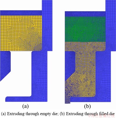
Fig. 1 Finite element models for welding formation
The material of the first billet was Al1100, and the second was Al6061. The billet and die temperatures were 450 and 400 °C respectively. The ram speed was set as a constant of 1 mm/s for simplicity. Other process conditions were set as of follows: interface heat 11 kW/(mm2・°C), friction factor billet-die: 1 (shear), friction factor of billet-die outlet: 0.6 (shear). All the tools were rigid and the billets were rigid-viscoplastic [12,13].
Firstly, the simulation ran a few steps to model the longitudinal welding formation in the empty die. After the entire die filled with extrusion metal, the new billet was added to model the billet-to-billet extrusion. Finally, oxides distribution under the two welding conditions was analyzed by point tricking technology.
2.2 Extrusion and experiments
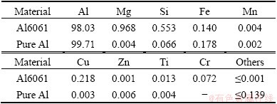
Considering the difficulty for prediction of the location of extrusion welding seam, the industrial experiment firstly was to extrude industrial pure aluminum as dummy billet and then a 6061 aluminum alloy billet. In this way, the shape of the transverse welding seam can easily be determined, because the pure aluminum develops a color different from Al6061. The compositions are listed in Table 1.
Table 1 Chemical composition of billet material (mass fraction, %)
Industrial extrusions were conducted on the 80 MN direct extrusion press at Aluminum Corporation of China Ltd. Profile’s wall thickness ranges from 20 to 35 mm. The extrusion ratio was 8.0, which was critical to welding seam formation. The die consisted of four mandrels supported by sixteen bridges. Temperatures for die and billets were 400 and 450 °C, respectively. Extrusion speed was adjusted to 25 mm/s in order to achieve optimum extrusion properties, and subsequent aging was performed to achieve a T6 peak-hardened temper. Two types of tensile samples (A, B in Fig. 2) were cut in the transverse direction. Care was taken during machining to ensure that the weld seam was located at the center position of the test piece (sample A in Fig. 2).
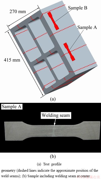
Fig. 2 Sample position and welding seam
The ambient temperature tensile property tests were performed on CSS-44100 electronic universal testing machine at a tensile velocity of 2 mm/min. Relevant samples were selected for fractographic examination using a Quanta-200 scanning electron microscope. Metallographic samples were cross-sectioned parallel to the extrusion direction. The samples were anodized in the Barker’s solution at 25 V for 5 min, and grain structures were observed by OM under polarized light using a XJP-6A microscope.
3 Results
The macrographs with visible extrusion weld stripes in transverse and longitudinal sections cut from the profile are shown in Fig. 3. The parts with white color come from the first extruded billet of pure aluminum, which may consist of both longitudinal and transverse welding zones.
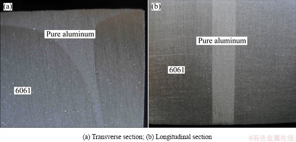
Fig. 3 Macrograph of welding zone
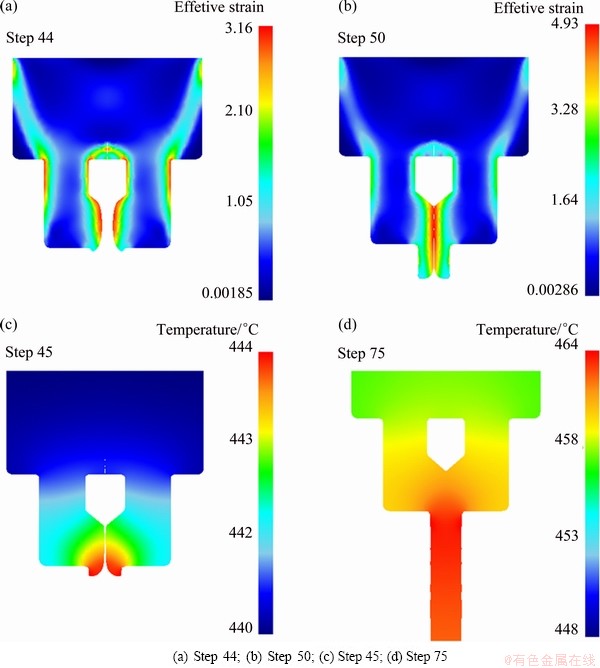
Fig. 4 Effective strain (a, b) and temperature (c, d) distribution during longitudinal welding formation
3.1 Longitudinal welding
Figure 4 presents the flow of two contiguous metal streams toward each other behind the die web in an empty die. When the metal streams reach the bottom of the welding chamber, the metal flows sideways. Affected by the friction of the die inner walls, the metal at the mid-height of the welding chamber flows faster (Fig. 4(a)). While the top and the bottom of the welding chambers are not completely filled, intimate contact between two contiguous metal streams at the mid-height of the welding chamber has been established (Fig. 4(b)). Therefore, gas pockets may be formed behind the webs, leading to deteriorated weld quality as reflected in poor fracture toughness [4]. Finally, the two metal streams are integrated to form a sound weld seam (Fig. 4(b)) under the web where the effective stress is the largest.
It can be seen that when the metal flows into the mandrel, divides and flows through the portholes, the temperature decreases from the initial billet temperature of 450 °C to 440-444 °C as a result of heat loss to the container and the porthole die, both of which had an initial temperature of 400 °C (Fig. 4(c)). As the metal flows sideways in the welding chamber and the neighboring metal streams contact each other, more mechanical work is done due to the severe local shear deformation(Figs. 4(c) and (d)), which is converted to heat to raise the temperature of the billet [2]. As a result, the temperature of the metal in the porthole stays stably at 448-464 °C (Fig. 4(d)).
3.2 Transverse welding
Under the billet-to-billet condition, the two billets are initially in contact and the interface is straight (Fig. 5(a)). After the extrusion process started, the new billet is impressed into the previous one and the two billets start to weld together with a curved welding interface (Figs. 5(b, c)).
It is clear that the previous billet is retained in the stagnant zone behind the bridge. The metal from this zone slowly seeps into the profile for a considerable length in continued extrusion (Fig. 5(e)). Actually, the transverse weld seams in the middle of the extrudate is indeed formed from the remnants of the previous billets. As the extrusion processes, the thickness (t in Fig. 5(e)) of the layer formed by previous billet decreases. Figure 5(e) reveals that this theoretical layer thickness has never disappeared [10]. If the oxides or some contaminations pack into the dead zone here, an inferior transverse welding quality will be induced [8-10].
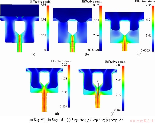
Fig. 5 Transverse welding formation and effective strain distribution of different simulation steps
3.3 Oxide distribution
When extruding through an empty porthole die (Fig. 6(a)), the oxide layer located above the webs and die would be pressed firmly and stick to the surface, and it will be removed after end of the first extrusion when the butt is sheared off. The oxide surface located centrally over the die cavities, however, would flow through the die cavities and occur as the external surface of the profile(Fig. 6(a)). Virgin metal from the inner part of material forms the longitudinal welding seam, thus no oxide exists at the interface between the matrix and longitudinal welding zone.
During the billet-to-billet extrusion through the porthole die (Fig. 6(b)), the surfaces are compressed intimately together at high temperatures. As the pressure between the two mating surfaces increases, high asperities of the surfaces come in contact and get crushed. It is generally considered that the oxide layer is less ductile than the bulk aluminum metal. Therefore, the oxide film of the interface would be broke into island- shaped flakes during heavy plastic deformation (Fig. 6(b)). Because of the high pressure inside the deformation zone, part of the clean metal of the two bodies in contact will extrude through the holes between the oxide flakes. As a consequence, the surfaces with lots of small oxide flakes were pressure-welded firmly together.
3.4 Microstructural characteristics
Figure 7 shows the typical grain feature in the matrix and extrusion welding zones.
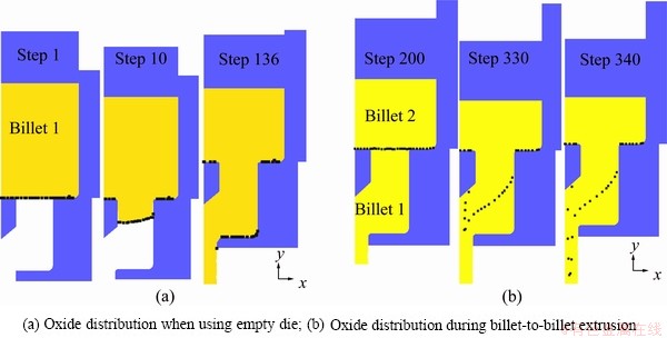
Fig. 6 Point trick for depicting distribution of oxides (black dots represent oxides)
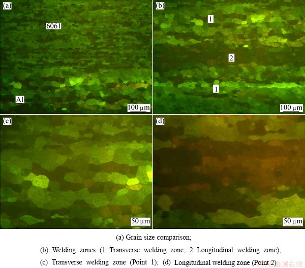
Fig. 7 Metallographic cross-section microstructures through welding zone parallel to extrusion direction
In the matrix, the microstructure consists of fine and elongated recrystallized grains which reserve some extrusion characteristics with an average size of 20-25 μm (Fig. 7(a)).
Equiaxed grains are observed in the transverse welding zone on both sides of the longitudinal welding seam, and the abrupt increasing of grain size to 40-50 μm is evidence (point 1 in Fig. 7(b)). This may be explained by the complete dynamic recrystallization effect and grain growth during extrusion and aging (Fig. 7(c)).
The longitudinal welding zone is recognizable as a darker etching band (point 2 in Fig. 7(b)) with the largest grain in it (Fig. 7(d)). The grains are 50-100 μm with irregular shape indicating a heavy deformation or high temperature affected zone presented under the die webs. The results are in agreement with the effective strain and temperature distribution analysis in the FE simulation.
3.5 Tensile properties and SEM analysis
The tensile test results of the matrix and welding seam samples respectively are σb 315.6 MPa, σ0.2 255.7 MPa, δ 10.2% and σb 81.9 MPa, σ0.2 64.9 MPa and δ 6.6%. From the absolute values of the tensile properties of each alloy, it can be concluded that the extrusion parameters are sufficient to achieve the T6 properties. Although the tensile result of welding seam sample has no comparability, the fractographies provide more useful information for the fracture origin and route. Figure 8 shows the typical fracture surfaces of the matrix and welding seam.
For the matrix sample, there are many dimples on the fracture surface, which indicates that the failure is the ductile fracture (Fig. 8(a)). However, the fracture feature of welding seam samples is more complex. With reference to Fig. 8(b), three distinct fracture areas are identified. The first area, A1, which represents the transverse welding area, shows no indications of dimple formation and a few oxides. The adjacent area, A2, reveals some inter-granular crack characteristics and partial bonding. In this case, the quasi-cleavage planes are observed on the fracture surface. The third area, A3, which represents the longitudinal welding zone, reveals dimples and a rough surface topography. Obviously, the load bearing capacity of area A3 is significantly greater than the other two areas, which, in practice, make it impossible to tear the specimens further apart along the welding seam [14].
The composition distribution along the matrix and welding zone is shown in Fig. 9.
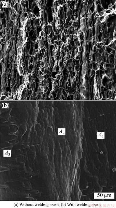
Fig. 8 SEM images of fracture surfaces after tensile test
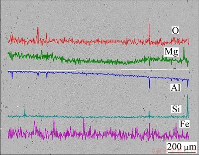
Fig. 9 Composition line scanning of extrusion welding zone
The enrichment of oxygen element at the interface between matrix and transverse welding zones indicates that there are oxide layers between the previous billet and the new one. This phenomenon confirms the results of the FEM and fracture feature of welding seam samples.
4 Discussion
Although several FE models had been developed to simulate the formation of extrusion welding seam in the past few years, actual material bonding was seldom taken into account, which resulted in a confusion of the difference between longitudinal and transverse welding zones. The position and shape of the welding areas in a transverse view are depicted in Fig. 10, the black dots and figures 1, 2 in Fig. 10 represent the oxides and the transverse and longitudinal welding zones, respectively. It is clear that after a while of extrusion, the bulk under the die webs consists of the longitudinal welding seam in the middle and the transverse welding zones on the sides.
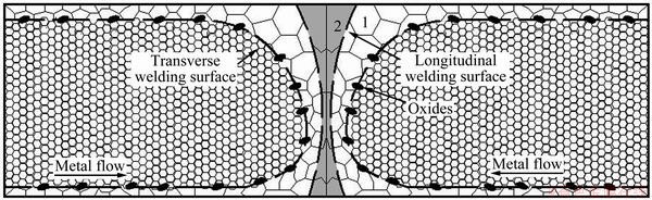
Fig. 10 Schematic diagram of extrusion welding in cross section
The longitudinal welding seam was generally considered including amount of oxides while the transverse welding formed by virginal metal from the inner of billet which had no oxides and contaminations [1,2]. However, the results of present study based on the FE and SEM reveal that oxides only exist at the interface between the matrix and transverse welding zone, which are opposite to previous researches. Actually, when cut off the length of extrude including the transverse welding zone, the mechanical properties of the left extrude are excellent except for the unconscionable die design and extrusion conditions. Noting the fact that the longitudinal welding seam could not be avoided during porthole die extrusion, the mechanical property and structural integrity might largely depend on the quality of transverse welding seam.
The microstructural differences between the longitudinal and transverse welding zones (Fig. 7(b)) were observed for the first time. Previous researches confused the differences between the longitudinal and transverse welding zones [15]. One must make it clear that the longitudinal welding is different from the transverse welding areas with a darker etching band (Fig. 7(b)) which may be due to the formation of deformation texture and the abnormal grain growth in comparison with that of other parts(Figs. 7(c) and (d)). The longitudinal welding zone under the die web always endures the heavy shear deformation and relatively high temperature (Fig. 4), which leads to the abnormal grain growth in extrusion welding zone.
5 Conclusions
1) There are no oxides exist in the longitudinal welding seam. The enrichment of oxides exists at the interface between the matrix and the transverse welding zone. This result is opposite to the researches reported elsewhere.
2) Because of the abnormal grain growth under heavy shear deformation and high temperature, the longitudinal welding zone is revealed as a darker band with the largest grain of irregular shape. There are large equiaxed recrystallized grains in transverse welding zone; however, the grain size is a little finer than that in longitudinal welding zone.
References
[1] VALBERG H. Extrusion welding in aluminum extrusion [J]. International Journal of Materials and Product Technology, 2002, 17(7): 497-556.
[2] LIU G, ZHOU J, DUSZCZYK J. FE analysis of metal flow and weld seam formation in a porthole die during the extrusion of a magnesium alloy into a square tube and the effect of ram speed on weld strength [J]. Journal of Materials Processing Technology, 2008, 200(1-3): 185-198.
[3] AKERET R. Productivity in extruding aluminum alloys [J]. Materials Research and Advanced Techniques, 1971, 62(6): 451-456.
[4] VALBERG H, LOEKEN T, HVAL M, NYHUS B, THAULOW C H. The extrusion of hollow profiles with a gas pocket behind the bridge [J]. International Journal of Materials and Product Technology, 1995, 10(3-6): 222-267.
[5] DONATI L, TOMESANI L, MINAK G. Characterization of seam weld quality in AA6082 extruded profiles [J]. Journal of Materials Processing Technology, 2007, 191(1-3): 127-131.
[6] DONATI L, TOMESANI L. The effect of die design on the production and seam weld quality of extruded aluminum profiles [J]. Journal of Materials Processing Technology, 2005, 164-165(15): 1025-1031.
[7] DONATI L, TOMESANI L. The prediction of seam welds quality in aluminum extrusion [J]. Journal of Materials Processing Technology, 2004, 153-154(1-3): 366-373.
[8] KHAN Y A, VALBERG H S, JACOBSE B O T. Deformation conditions in the extrusion weld zone when using pointed and square ended bridge [J]. International Journal of Materials Form, 2010, 3(l): 379-382.
[9] KHAN Y A, VALBERG H S, IRGENS I. Joining of metal streams in extrusion welding [J]. International Journal of Materials Form, 2009, 2(1): 109-112.
[10] KHAN Y A, VALBERG H S. Metal flow in idealized a symmetric 2D extrusion welding [J]. International Journal of Materials Form, 2010, 3(1): 383-386.
[11] CERETTI E, FRATINI L, GAGLIARDI F, GIARDINI C. A new approach to study material bonding in extrusion porthole dies [J]. CIRP Annals-Manufacturing Technology, 2009, 58(1): 259-262.
[12] OH S I, WU W T, TANG J P, VEDHANAYAGAM A. Capabilities and applications of FEM code DEFORM: The perspective of the developer [J]. Journal of Materials Processing Technology, 1991, 27(1-3): 25-42.
[13] LI Q, HARRIS S, JOLLY R K. Finite element modeling simulation of transverse welding phenomenon in aluminum extrusion process [J]. Materials and Design, 2003, 24(7): 493-496.
[14] LILLEBY A, GRONG  HEMMER H. Experimental and finite element simulations of cold pressure welding of aluminum by divergent extrusion [J]. Materials Science and Engineering A, 2009, 527(1-2): 179-186.
[15] JO H H, LEE S K, LEE S B, KIN B M. Prediction of welding pressure in the non-steady state porthole die extrusion of Al7003 tubes [J]. International Journal of Machine Tools and Manufacture, 2002, 42(6): 753-759.
分流模挤压焊合区域的氧化物分布及焊合组织分析
张新明1,冯 迪1,史兴宽2,刘胜胆1
1. 中南大学 材料科学与工程学院,长沙 410083;
2. 中国航天二院 23所,北京 100024
摘 要:利用有限元分析、扫描电子显微镜及金相实验研究分流模的锭接锭挤压条件下,型材纵、横向焊合区域的氧化物分布及焊缝微观组织。结果表明:氧化物仅存在于型材基体与横向焊合区域结合面;纵向焊缝表现为深色条纹状组织,包含在强剪切变形及高温条件下形成的粗大再结晶晶粒中;横向焊缝组织表现为晶粒度略小的等轴再结晶晶粒。
关键词:分流模;挤压焊合;氧化物分布;焊合组织
(Edited by Xiang-qun LI)
Foundation item: Project (2012CB619501) supported by the National Basic Research Program of China; Project supported by the Chinese Defence Advance Research Program of Science and Technology
Corresponding author: Xin-ming ZHANG; Tel: +86-731-88830265; E-mail: xmzhang_cn@yahoo.cn
DOI: 10.1016/S1003-6326(13)62527-3

