


Trans. Nonferrous Met. Soc. China 22(2012) 2431-2438
Lubrication properties of Nitinol 60 alloy used as high-speed rolling bearing and numerical simulation of flow pattern of oil-air lubrication
ZENG Qun-feng, ZHAO Xi-meng, DONG Guang-neng, WU Hong-xing
Key Laboratory of Ministry of Education for Modern Design and Rotor-Bearing System,
Xi’an Jiaotong University, Xi’an 710049, China
Received 9 July 2012; accepted 1 August 2012
Abstract: The friction and wear tests were performed using Nitinol 60 alloy pin sliding over GCr15 steel disk in a pin-on-disk tribometer system under PAO oil lubrication conditions. It was found that Nitinol 60 alloy can be lubricated well and has shown remarkable tribological performance. Average coefficient of friction (COF) of Nitinol 60 is 0.6 under dry friction; however, average COF decreases to 0.1 under PAO oil lubrication. SEM image of the worn surface shows that Nitinol 60 exhibits excellent wear resistance and the wear mechanism is mainly adhesive wear. Flow pattern of oil-air flow in oil pipe was simulated by FLUENT software with VOF model for acquiring working performance of oil-air lubrication. The optimum velocity of oil and air at the inlet was achieved, which provides the great proposal for the design of experiment of oil-air lubrication of Nitinol 60 alloy. The simulation results showed that the optimum annular flow of flow pattern was obtained when air velocity is 10 m/s and oil velocity is 0.05 m/s. The formation mechanism of annular flow was also discussed in the present study.
Key words: Nitinol 60 alloy; lubrication properties; oil-air lubrication; numerical simulation; two-phase flow
1 Introduction
Nitinol 60 alloy, an intermetallic nickel-titanium alloy containing 60% (mass fraction) nickel and 40% titanium, has been extensively used due to its superior mechanical and chemical properties [1]. Nitinol 60 is hard, electrically conductive, highly corrosion resistant, less dense than steel, readily machined prior to final heat treatment, non-galling and non-magnetic, which exhibits excellent useful structural properties and offers a broad combination of properties that make it unique among bearing materials. No other bearing alloy, metallic or ceramic, claims all of these attributes [2-4]. The performance equaled or exceeded that observed with silicon nitride or traditional steel-based bearing materials such as titanium carbide-coated 440C, M50 and 52100 steel [5,6]. These steel materials suffer from corrosion attack if not protected and they are highly magnetic. In addition, when used as bearing rolling elements, their high density leads to high centrifugal forces and limited fatigue life [7]. These considerations have driven the development of alternate bearing materials [8]. Low density of silicon nitride compared with that of steels makes it ideal for high-speed applications because of low centrifugal stress. However, it is more expensive to manufacture than steel due to the complexity and cost of high temperature and high-pressure powder metallurgy processing [9].
Nitinol 60, when appropriately heat-treated, does not exhibit shape memory effect (SME) properties at normal ambient. It is 26% in density lower than steel for weight sensitive applications such as aircraft, satellites and spacecraft. Based on these special characteristics, Nitinol 60 appears to be an excellent candidate material for high-speed rolling bearings. Researches indicate that COF of Nitinol 60, not like traditional titanium alloys such as Ti-6Al-4V with poor tribological property even under well lubricated conditions by oils and greases [10], is around 0.5 in dry sliding [11]. Clearly, researches will be required to understand the tribological properties of Nitinol 60 under oil lubrication, especially when Nitinol 60 is used as the bearing materials for high-speed rolling bearing. Oil-air lubrication system has the advantages of high cooling efficiency, high lubricating efficiency, environmental benefits and precise oil quantity control [12]. It has better cooling effect than the traditional oil lubrication due to high-speed compressed air [13]. Although oil-air lubrication of steel bearing has been used to high-speed bearing [14], no information about TiNi alloy rolling bearing is available. The bearing performance depends on its operating parameters such as load, environmental temperature, speed, lubricant type (liquid, grease or solid) and lubricant supply method (oil immersion, oil jet, oil mist, oil/air, etc) [15]. In application, it is difficult to predict the optimum value for each of these parameters [16,17]. Numerical simulation has been developed in an attempt to rationalize oil-air lubrication parameter optimization, design evaluation and prediction of lubrication properties [18,19]. In recent years, as computing costs have decreased, computational fluid dynamics (CFD) has found widespread applications, particularly in the simulation of complicated flows [20]. Numerical simulation is an effective and economical method for analysis of oil-air two-phase flow [21]. The goal firstly is to perform an experimental evaluation about lubrication properties of Nitinol 60 alloy, and then FLUENT software with volume of fluid (VOF) model is used to simulate flow pattern of oil-air flow in order to obtain optimum oil-air lubrication parameter in the present work.
2 Experimental
Friction and wear tests were carried out using pin-on-disk tribometer under oil lubrication conditions. PAO oil was used as lubricant. The physical properties of Nitinol 60 alloy pin, sliding under rotation motion against GCr15 steel disc, are shown in Table 1. The normal load was 22.92 N and sliding velocity was 0.219 m/s. The average contact pressure was around 220 MPa. It was assumed pin with 6 mm in diameter and 15 mm in length contacted steel disc with 30 mm in diameter and 5 mm in thickness directly. Nitinol 60 pin was polished to surface roughness Ra=0.22 μm. GCr15 steel disc was polished to surface roughness Ra=0.006 μm. The humidity was strictly controlled to (30±2)% RH in ambient air and room temperature of (24±1) ℃ in the laboratory. The friction tests were run three times for each combination of pairs and a new area on disc and pin was used for each test respectively. Before starting the friction tests, the specimen was cleaned using acetone in an ultrasonic bath for 10 min and the disc surface was pre-lubricated with 10 μL of lubricant followed by bidirectional wiping. After the friction tests, the worn surface was observed by scanning electron microscopy (SEM).
Table 1 Physical properties of Nitinol 60 alloy

3 Experimental results
Figure 1 shows COF of Nitinol 60 pin during sliding against GCr15 steel disc versus sliding time under dry friction and oil lubrication conditions, respectively. It was found that the tendency of COF with sliding time is completely different. COF is low (around 0.1) at initial step; and then increased slowly to 0.6 with increasing sliding time in fluctuation under dry friction. However, COF was constant around 0.11 under PAO oil lubrication, irrespectively of sliding time. Average COF of Nitinol 60 alloy at steady step is about 0.57 under dry friction, but 0.11 was maintained under oil lubrication. The friction behavior is remarkable under PAO oil lubrication. For metal, it is well known that the friction behavior is strongly dependent on lubrication type. Under oil lubrication, COF decreases as oil film is formed between Nitinol 60 and GCr15 frictional contact surface. Low and stable COF was maintained over a long period because it may result from lubrication effect of oil film.
SEM images of the worn surface of Nitinol 60 are shown in Fig. 2. It was found that the wear groove is clearly formed on the worn surface under dry friction and some big wear debris can be found at the edges and on the wear track. However, it appears to be uniform and smooth on the worn face. There are small dents along with sliding direction, which indicates adhere wear. Apparently, PAO oil is beneficial to the tribological properties of Nitinol 60 under oil lubrication.

Fig. 1 COF curves obtained under dry friction (a) and oil lubrication (b)

Fig. 2 SEM images of worn surface of TiNi60 under different friction conditions: (a) Dry friction; (b) Oil lubrication
4 Numerical simulation model
FLUENT is a popular and commercial software based on CFD. It is widely used in hydrodynamics modeling. FLUENT is an appropriate software that is used for simulating and analyzing the fluid flow and heat transfer in complex geometric area.
4.1 Hydrodynamics modeling
4.1.1 Fluid medium
Air and PAO oil are used as gas and fluid in oil-air lubrication system, respectively. PAO oil has excellent properties such as a low volatility, high thermostability and viscosity index. Table 2 shows the physical properties of air and PAO oil, respectively.
4.1.2 Physical model
The law of fluid flow is the basis of establishing fluid movement equations. The control of fluid flow, heat and mass transfer and other process are listed into mathematical formula. Governing equations of oil supply system were derived from continuity and momentum equations. The governing equations are listed in the following.
Table 2 Physical properties of PAO oil and air

1) Mass conservation equation
 (1)
(1)
2) Conservation of momentum equation
 (2)
(2)
where p is the static pressure; τij is the stress tensor; ρgi and Fi are body-forced gravity and extern body force in i direction, respectively.
Stress tensor are given by
 (3)
(3)
where τij is the component of τ which is the viscosity stress produced on the surface of micro unit body due to molecular viscosity.
3) Conservation of energy equation

 (4)
(4)
where keff is the effective thermal conductivity; Jj is the diffusion flow of component j; Sh includes chemical action heat and body heat; E is calculated by equation
 . Heat transfer between oil and air is
negligible, so this law is ignored.
4) Physical model and mesh generation
The pipe had 500 mm in length and 10 mm in diameter. Based on measured dimension for pipe, three dimensional CAD model was developed to write input data for the grid generation program. The generated grid is shown in Fig. 3.
One end of pipe is the entrance to air and another end of pipe is outlet of the mixture phase. The inlet of oil is located where distance is 20 mm far from inlet of air and also perpetual with the inlet direction of air. The diameter of inlet is 4 mm. It was meshed when the physical model was built. In general, the tetrahedral grid is easily meshed, but the calculated results are not precisely accurate. Therefore, the hexahedron grid used in spite of grid meshing is difficult and the calculated results are relatively accurate. The shape of oil inlet was simplified to square pipe in order to mesh the hexahedron grid easily. The grid is intensive near the pipe wall in order to observe two-phase flow clearly. The pipe is mode from the symmetric fabric; therefore, half of pipe is used to save time, as shown in Fig. 3.
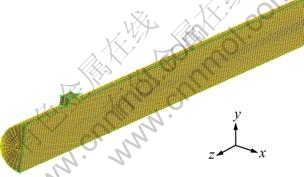
Fig. 3 Grid system of pipe
5) Physical model simplification
To simplify simulation analysis of oil-air lubrication, the following assumptions are given in the present model:
(a) There is no phase transformation in oil;
(b) Heat transfer between oil and air is negligible, and the properties such as control volume, pressure and temperature are constant for working fluid;
(c) Pressure is zero and there is no effluent recycling at outlet of pipe for mixture phase flow;
(d) Air is regarded as the compressible flow, but air is considered incompressible flow when Mach number is less 0.3.
4.1.3 Solver
The pressure-based solver is chosen as solver, which is suitable for low velocity and incompressible flow. The implicit formulation was used because it can obtain convergent solution quickly. The transient state parameter is used in the time option to obtain the flow pattern map because flow pattern is an unsteady process.
4.1.4 Two-phase flow model
1) Fluid type of two-phase flow
Two-phase flow was to be separated when two-phase fluid flows in the horizontal pipe due to the gravity.
Two-phase flow model is grouped into six categories: bubbly flow, air plug flow, laminar flow, wave undular laminar flow, slug flow and annular flow. In the bubbly flow, most of bubbles are in the top of the pipe under the gravity. When air flow rate increases, small bubbles are merged into air plug flow. Laminar flow is suitable because air and fluid flow rates are small and the interface of two phases is smooth. When air phase flow rate becomes high, flow wave occurs at the interface of two-phase flow, an two-phase flow becomes undular laminar flow. If air phase flow rate is so high, two-phase flow will become slug flow. Annular flow occurs when air flow rate is high and fluid flow rate is little. Annular flow fluid type was chosen as the fluid flow type when the velocity of air flow is high. In the annular flow, the lubrication will be obtained when the least oil content is used.
2) Two-phase flow model
VOF (volume of fluid) model was used to analyze two-phase mixture flow of oil and air in pipe. Two-phase flow model can be used if fluids are not dissolved each other. There is a remarkable interface when the mixture of oil and air flows in the horizontal pipe.
4.1.5 Turbulence mode
Turbulence models can be broadly grouped into three categories. First category is the turbulent transport coefficient model. The task of turbulence or turbulence closure model is to calculate the turbulent viscosity coefficient of the expression or its transport equation approach. The second category is abandoned the concept of turbulent transport coefficients, the direct establishment of the turbulent stress and the amount of other second-order correlation transport equation. The third category is large-eddy simulation. Large-eddy simulation to turbulent flow into large-scale turbulence and small-scale turbulence, as amended by solving three-dimensional Navier-Stokes equations, has been movement of large vortex characteristics, and movement of small vortex model used above [22].
Turbulence models provided by FLUENT include: single-equation (Spalart Allmaras) model, two-model (standard) model, Revised model and Reynolds stress model and large-eddy simulation, etc. Turbulence model of Reynolds stress is the most fine turbulence model in FLUENT software. It neglects the vortex viscosity of isomorphism, and solves Reynolds stress equations directly. The calculated quantity of Reynolds stress is large. The turbulence model of Reynolds stress can be used when the anisortropy of Reynolds stress is considered. There is the secondary flow in the horizontal pipe. Therefore, the turbulence model of Reynolds stress is chosen in the present work.
4.1.6 FLUENT parameters setting
1) Pressure
It is important that the setting of pressure in numerical simulation process. It affects the calculated results significantly. The pressure is set firstly as atmospheric pressure in FLUENT software.
2) Boundary conditions
The physical condition is met under the calculated boundary conditions in flow field. Velocity at inlet of pipe where oil-air two-phase entering the pipe was determined through outlet. The boundary condition at outlet of oil pipe was evaluated from exit pressure of oil pipe.
3) Parameters of turbulence
The turbulence intensity and diameter of water power should be set. The turbulence intensity is referred as the ratio of average flow velocity. The diameter of water power, which represents the limit of turbulence flow, is set as the diameter of pipe.
 (5)
(5)
where Re is Reynolds number.
4) Operating pressure
The atmosphere pressure is used as operating pressure. The gravity acceleration is considered in negative y direction.
5 Simulation results and discussion
Air velocity is 10 m/s and oil velocity is 0.05 m/s, 0.5 m/s or 10 m/s. Flow pattern of two-phase flow was investigated under these parameters.
Figure 4 shows the distribution of two-phase flow on the symmetry plane when air velocity is 10 m/s and oil velocity is 0.05 m/s, 0.5 m/s or 10 m/s. It was found that oil moves along with upper pipe wall under a small oil velocity. However, oil moves downward firstly along inlet of pipe when oil velocity increases, and then sticks and moves upward along the pipe wall under air promoting.

Fig. 4 Distribution of two-phase flow on symmetry plane at different oil velocities: (a) v(oil)=0.05 m/s; (b) v(oil)=0.5 m/s; (c) v(oil)=10 m/s
Figure 5 shows the distribution of two-phase flow on pipe wall when air velocity is 10 m/s and oil velocity is 0.05 m/s, 0.5 m/s or 10 m/s. Results show that oil covers the whole pipe wall at initial stage from the top of the pipe toward the bottom of pipe under a small oil velocity. However, oil covers whole pipe wall from the bottom of the pipe toward the top of pipe when oil velocity increases. The reasons may be principally that interactions between oil and air increase due to the increasing oil content in mixture chamber with increasing oil velocity, and there is a counteracting force producing when oil impacts the bottom of pipe wall under high speed. This fore makes oil move upward along the bottom of pipe wall, but this phenomenon only happens at the inlet of the oil.
Figure 6 shows the distribution of two-phase flow at different positions along with z-axial profile when air velocity is 10 m/s and oil velocity is 0.05 m/s. It is shown that secondary flow of two-phase flow is formed. Air moves downward along the pipe wall and then moves upward nearby the symmetry plane. Air forms two vorticity motions. Air vorticity has a great effect on the movement of oil. Oil moves downward along the pipe wall from the top of the pipe under the secondary flow and the gravity at the same time, and then finally becomes an annular flow of flow pattern.

Fig. 5 Distribution of two-phase flow on pipe wall at different oil velocities: (a) v(oil)=0.05 m/s; (b) v(oil)=0.5 m/s; (c) v(oil)=10 m/s

Fig. 6 Distribution of two-phase flow at different positions on z-axial profile at air velocity of 10 m/s and oil velocity of 0.05 m/s: (a) z=470 mm; (b) z=350 mm; (c) z=0 mm
Figure 7 shows the distribution of two-phase flow at different positions of z axial profile when air velocity is 10 m/s and oil velocity is 0.5 m/s. Results show that oil escaped from attachment effect of pipe wall and failed to the center of pipe under the gravity with increasing oil velocity. The direction of the secondary flow in the pipe is the same as 0.05 m/s of oil velocity. The oil will move downward and become an annular flow of flow pattern under air promoting.

Fig. 7 Distribution of two-phase flow at different positions on z-axial profile at 10 m/s of air velocity and 0.5 m/s of oil velocity: (a) z=470 mm; (b) z=350 mm; (c) z=0 mm
Figure 8 shows the distribution of two-phase flow at different positions along with z axial profile when air velocity is 10 m/s and oil velocity is 10 m/s. Oil moves down to the bottom of the pipe. The direction of the secondary flow in the pipe is opposite with 0.05 m/s of oil velocity. The oil moves upward along the pipe wall under the secondary flow, overcoming the gravity at the same time. However, oil will fall down to the bottom of pipe with increasing the amount of oil.

Fig. 8 Distribution of two-phase flow at different positions on z-axial profile at 10 m/s of air velocity and 10 m/s of oil velocity: (a) z=470 mm; (b) z=350 mm; (c) z=0 mm
Results show that oil moves upward along pipe wall when oil velocity is small and then moves downward along with pipe wall, forming annular flow under the gravity. Oil penetrated into air phase and impacted the bottom of pipe directly. Two-phase flow was laminar flow at initial stage. Then it becomes annular flow when the oil moves upward along with pipe wall to the top of pipe and oil moves toward two lateral surfaces along with pipe wall under the air, promoting meeting together. The annular flow becomes uniformly with time increasing along with pipe.
6 Conclusions
Nitinol 60 is proposed to be a promising candidate material for high-speed rolling bearing. Lubrication property of Nitinol 60 was investigated by pin-on-disc tribometer under dry friction and oil lubrication, respectively. In addition, flow pattern of air-oil flow for high-speed rolling bearing was simulated with FLUENT software. The results are listed as the following.
1) Nitinol 60 exhibits excellent tribological properties under PAO oil lubrication. Average COF of Nitinol 60 at steady-stable stage is 0.6 under dry friction; however, average COF is 0.1 under oil lubrication. The wear-resistant behavior is improved under oil lubrication. The wear mechanism of Nitinol 60 is mainly adhesive wear.
2) Numerical simulation results show that oil velocity influences flow pattern of oil-air two-phase flow strongly. In symmetry plane, the oil moves directly from upward to downward of pipe wall with increasing oil velocity. In pipe wall, the movement of oil directs from top to bottom of pipe wall with increasing oil velocity. The best annular flow of flow pattern is achieved when air velocity is 10 m/s and oil velocity is 0.05 m/s. Moreover, annular flow distribution of two-phase flow along with z-axial profile becomes gradually uniform. At outlet of mixture oil-air flow, annular flow is the best in the pipe, which is agreement with our aim of oil-air lubrication.
References
[1] KHAMEI A, DEHGHANI K. A study on the mechanical behavior and microstructural evolution of Ni60wt%-Ti40wt% (Nitinol 60) intermetallic compound during hot deformation [J]. Materials Chemical and Physics, 2010, 123: 269-277.
[2] WANG L, SNIDLE R, GU L. Rolling contact silicon nitride bearing technology: A review of recent research [J]. Wear, 2009, 246: 159-173.
[3] KATZ R, HANNOOSH J. Ceramics for high performance rolling element bearings: A review and assessment [J]. Materials and Design, 1987, 8(2): 108-112.
[4] SHODA Y, IJUIN S, ARAMAKI H, YUI H, TOMA K. The performance of a hybrid ceramic ball bearing under high speed conditions with the under-race lubrication method [J]. Tribology Transaction, 1997, 40(4): 676-684.
[5] DELLA CORTE C, PEPPER S, NOEBE R, GLENNON G. Intermetallic nickel-titanium alloys for oil lubricated bearing applications [J]. Power Transmission Engineering, 2009, 8: 26-35.
[6] FORSTER N, ROSADO L, OGDEN W, TRIVEDI H. Rolling contact fatigue life and spall propagation characteristics of AISI M50, M50 NIL and AISI 52100, Part Ⅲ: Metallurgical examination [J]. Tribology Transactions, 2009, 53: 52-59.
[7] WANG Y, FERNANDEZ J, CUERVO D. Rolling contact fatigue lives of steel AISI 52100 balls with eight mineral and synthetic lubricants [J]. Wear, 1996, 196: 110-115.
[8] ZEREN A. Embeddability behavior of tin-based bearing material in dry sliding [J]. Materials & Design, 2007, 28: 2344-2350.
[9] SUN Li, MALSHE A, JIANG Wen-ping, MCCLUSKEY P. Experimental investigation of laser surface processing of flexure silicon nitride ceramic [J]. Transactions of Nonferrous Metals Society of China, 2006, 16: 558-565.
[10] BANSAL D, ERYILMAZ L, BLAU P. Surface engineering to improve the durability and lubricity of Ti-6Al-4V alloy [J]. Wear, 2011, 271: 2006-2015.
[11] PEPPER S, DELLA CORTE C. Lubrication of Nitinol 60 [R]. NASA/TM-2010: 215331-1-8.
[12] WU C, KUNG Y. A parametric study on oil/lubrication of a high speed spindle [J]. Precision Engineering, 2005, 3: 73-75.
[13] JIANG S, MAO H. Investigation of the high speed rolling bearing temperature rise with oil-air lubrication [J]. Transaction of the ASME Journal of Tribology, 2011, 133: 021101-1-7.
[14] YEO S, RAMESH K, ZHONG Z. Ultra high speed grinding spindle characteristics upon using oil/air mist lubrication [J]. International Journal of Machine Tools and Manufacture, 2002, 42: 815-823.
[15] RAMESH K, YEO S, ZHONG Z. Ultra-high-speed behavior of a rolling element upon using oil-air/mist lubrication [J]. Journal of Materials Processing Technology, 2002, 127: 191-198.
[16] JENG Y, GAO C. Investigation of the ball-bearing temperature rise under an oil-air lubrication system [J]. Journal of Engineering Tribology, 2001, 215: 139-148.
[17] HOSANG G. Experimental and computed performance characteristics of high speed silicon nitride ball bearing [J]. Transactions of the ASME Journal of Engineering for Gas Turbines and Power, 1991, 113: 635-642.
[18] XU J, CHENG P, ZHAO T. Gas-liquid two phase flow regimes in rectangular channels with mini/micro gaps [J]. International Journal of Multiphase Flow, 1999, 25: 411-432.
[19] HETSRONI G, MOSYAK A, SEGAL Z, POGREBNYAK E. Two-phase flow patterns in parallel micro-channels [J]. International Journal of Multiphase Flow, 2003, 29: 341-360.
[20] LI Shan-hong, LI Cai-ting, ZENG Guang-ming, WANG Da-yong. CFD simulation on performance of new type umbrella plate scrubber [J]. Transactions of Nonferrous Metals Society of China, 2008, 18: 488-492.
[21] REZKALLAH K. Recent progress in the studies of two-phase flow at microgravity conditions [J]. Advances in Space Research, 1995, 16: 123-132.
[22] CHEN Shen-rong, XU Gao-chun, RUAN He-gen, ZHU Hong-ping, LI Li-min. Applications of computational fluid dynamics in design of oil-mist collection [J]. Design, 2009, 11: 910-913.
高速滚动轴承用TiNi60合金的润滑性能及油气润滑两相流流型的数值计算
曾群锋,赵西朦,董光能,吴红星
西安交通大学 现代设计及转子轴承系统教育部重点实验室,西安 710049
摘 要:销-盘摩擦磨损实验研究表明:TiNi60合金在PAO油润滑下具有优异的摩擦学性能,稳定阶段的平均摩擦系数由干摩擦的0.6降低到油润滑下的0.1,而且非常稳定。从SEM磨损形貌图可知:油润滑下TiNi60合金的磨损表面光滑,粘着磨损明显减弱。在实际研究中,仿真计算是获得高速滚动轴承在油气润滑下各项工作性能数据的有效方法。采用FLUENT数值计算了油-气两相流在水平管子内的流型分布,得到了最佳油、气的进口速度,为高速滚动轴承用TiNi60合金在油气润滑下的使用提供了理论依据。仿真计算结果表明:当空气速度为10 m/s和油速度为0.05 m/s时,可以得到最佳的环状流型分布。
关键词:钛镍60合金;润滑性能;油气润滑;数值计算;两相流
(Edited by YANG Hua)
Foundation item: Project (2012M511993) supported by China Postdoctoral Science Foundation; Project (TPL1202) supported by the Open Fund Program of the State Key Laboratory of Traction Power, Southwest Jiaotong University, China
Corresponding author: ZENG Qun-feng; Tel: +86-29-82667520; E-mail: qzeng@mail.xjtu.edu.cn
DOI: 10.1016/S1003-6326(11)61481-7

