J. Cent. South Univ. (2016) 23: 209-219
DOI: 10.1007/s11771-016-3064-6

Determination of reasonable finished state of self-anchored suspension bridges
LI Jian-hui(���)1, FENG Dong-ming(�붫��)2, LI Ai-qun(�Ⱥ)3, YUAN Hui-hui(Ԭ�Ի�)4
1. College of Civil Engineering, Nanjing Forestry University, Nanjing 210037, China;
2. Department of Civil Engineering and Engineering Mechanics, Columbia University, New York, NY 10027, USA;
3. College of Civil Engineering, Southeast University, Nanjing 210096, China;
4. College of Civil Engineering, Fuzhou University, Fuzhou 350116, China
 Central South University Press and Springer-Verlag Berlin Heidelberg 2016
Abstract: A systematic and generic procedure for the determination of the reasonable finished state of self-anchored suspension bridges is proposed, the realization of which is mainly through adjustment of the hanger tensions. The initial hanger tensions are first obtained through an iterative analysis by combining the girder-tower-only finite element (FE) model with the analytical program for shape finding of the spatial cable system. These initial hanger tensions, together with the corresponding cable coordinates and internal forces, are then included into the FE model of the total bridge system, the nonlinear analysis of which involves the optimization technique. Calculations are repeated until the optimization algorithm converges to the most optimal hanger tensions (i.e. the desired reasonable finished bridge state). The ��temperature rigid arm�� is introduced to offset the unavoidable initial deformations of the girder and tower, which are due to the huge axial forces originated from the main cable. Moreover, by changing the stiffness coefficient K in the girder-tower-only FE model, the stiffness proportion of the main girder, the tower or the cable subsystem in the whole structural system could be adjusted according to the design intentions. The effectiveness of the proposed method is examined and demonstrated by one simple tutorial example and one self-anchored suspension bridge.
Key words: self-anchored suspension bridge; reasonable finished bridge state; optimization algorithm; finite element; nonlinear relation
1 Introduction
Self-anchored suspension bridge has appealing aesthetics. One of the distinguishing features of the self-anchored system is that this kind of bridge system does not require massive end anchorages used for the typical earth-anchored suspension bridge [1]. Instead, the main cables are anchored to both ends of the stiffening girder. Over the past 20 years, many self-anchored suspension bridges have been constructed and opened to traffic. Well-known examples are the Yongjong Grand Bridge (125 m+300 m+125 m, Seoul) [2], the new San Francisco-Oakland Bay bridge (180 m+385 m, San Francisco) [3], Jiangdong Bridge (85 m+220 m+85 m, Hangzhou) [4], Liede Bridge (167 m+219 m, Guangzhou) [5] and Jiangxinzhou Bridge (35 m+77 m+60 m+248 m+ 35 m, Nanjing) [6].
The assurance of reasonable finished state of a self-anchored suspension bridge is important for its long-term operational behavior [5]. During the early design stage, some fundamental design parameters, like the control-point coordinates of the main cable, the sag-to-span ratio, the hanger positions, and the girder alignment, are first pre-determined based on the bridge overall layout and engineering experiences. Afterward, efforts can be made to calculate the hanger tensions and the shape, length and internal forces of the main cable system under the finished bridge state. Then, the empty state and construction state of the main cable could be calculated according to the principle of the invariance of the unstrained cable length. Consequently, determination of the reasonable finished state of self-anchored suspension bridge is a top priority.
Thus far, researches on the determination of the reasonable finished bridge state are mainly focused on that of the cable-stayed bridge, which is closely related to the determination of reasonable cable forces rather than the cable configuration [2, 7�C8]. For the ground-anchored suspension bridge, this procedure is relatively simple because the main cable is anchored on immovable ground [9]. In comparison, the determination of the reasonable finished state of self-anchored suspension bridge is much more complicated and more difficult because of its structural, mechanical and construction complexities. Very limited studies have appeared in the literature regarding this topic. KIM et al [2] proposed a two-step procedure for non-linear shape finding analysis of the Yongjong Grand Bridge. It is assumed that the vertical component of hanger tension is the portioned dead weight of the stiffening truss supported by the corresponding hanger, which is sometimes not the case. In the view of internal forces (especially bending moments) of the girder, LI et al [4] proposed a rapid method to find the shape of spatial main cable and hanger tensions in the finished bridge state. However, in the iterative calculation analysis, the total bridge system was replaced by a simplified continuous beam element model, with forces from the main cable and hangers applied on it. In addition, the unavoidable deformations of the girder and tower due to the huge axial forces originated from the main cable are not considered.
This study is motivated to develop a systematic and generic procedure for determination of the reasonable finished state of self-anchored suspension bridge. By combining the FE model and the analytical program for shape finding of spatial main cable system, the optimization algorithm is introduced into the determination of the reasonable finished state of self- anchored suspension bridges. The proposed procedure can fully consider the mechanical characteristics of self-anchored suspension bridge. The effectiveness of the proposed method is demonstrated by one simple tutorial example together with a spatial cable self-anchored suspension bridge.
2 Analytical calculation method of spatial cable system
Based on the nonlinear segmental catenary theory for the analysis of flexible cables, four assumptions are adopted [10�C11]:
1) The cable is ideally flexible, i.e., the cable can only bear tension and the sectional bending stiffness is zero;
2) The material of the cable is linear elastic and meets the Hook��s law;
3) The changes of the cross-section area of the cable before and after deformation are neglected;
4) The hangers are inclined only in the transverse bridge plane, i.e., the horizontal component of the main cable remains constant.
As shown in Fig. 1, the single-span cable is divided into n+1 segments by the n hanger forces, and each segment should satisfy the catenary conditions. So, the coordinate equation for the i catenary section can be formulated as follows:
 (1)
(1)
where HLXi and HLYi are the two horizontal components of the internal force of left end of the i catenary section, respectively; VLZi and VRZi are the vertical components of the internal force of left and right ends of the i catenary section, respectively; TLi and TRi are tensions of left and right ends of the i catenary section, respectively,  and
and  S0i is the unstrained cable length of the i catenary section; Wi is the weight, Wi=q��S0i, and q is the weight per unit length.
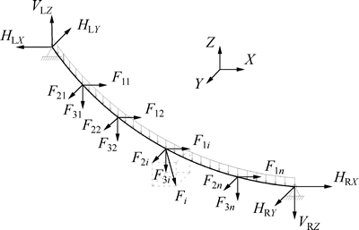
Fig. 1 Spatial cable under concentrate loads
According to the aforementioned assumption 3), three components of the main cable at the finished bridge state can be expressed as
 (2)
(2)
where F3i is the vertical component of the hanger force at the i point loading on the main cable, as shown in Fig. 2; Ybi and Zbi are the lateral and vertical coordinates of the anchorage end of the hanger at the i point, respectively.
Equations (1) and (2) constitute the fundamental equations for shape-finding analysis of spatial main cable system. If desired parameters in finished bridge state (like the sag-to-span ratio, control point positions of the main cables on the stiffening girder and tower, positions of each hanger, girder alignment, dead load distribution, etc) are given, the configurations and internal tensions of the main cable under the finished bridge state can then be determined. See Ref. [10] for details of the calculationprocedures, in which the analytical self-anchored suspension bridge analysis program (SSBAP) is developed by the authors.
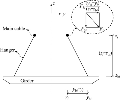
Fig. 2 Cable force model of cross-section
3 Determination principles for reasonable finished bridge state
The reasonable finished bridge state refers to the situation that the structure meets the design specifications and achieves optimal mechanical performances with respect to certain objectives. For self- anchored suspension bridges, the principles for the reasonable finished bridge state can be summarized as follows:
1) Overall mechanical behaviors of the structure are in good condition; the stiffness proportion of each component (i.e., the main girder, the tower or the cable system) in the whole structural system is rational; each component of structure can meet the safety requirements and retain reasonable safety margins under the most unfavorable load combination.
2) Hanger forces under dead load are uniformly distributed. However, although it is allowable that certain hanger force can have sudden change, overall, hanger force should not be too large or too small.
3) Moment of the tower in the finished bridge state is exact or close to zero. In an ideal situation, the tower is under axial compression. That is to say, the horizontal forces of the main cable on both sides of the tower must be equal to each other.
4) Under the dead load, the alignment of the main girder is smooth, and satisfies the design configurations. Under the most unfavorable dead and live load combination, deflections of main girder can meet requirements in the relevant bridge specifications.
5) No negative support reaction is allowable under the most unfavorable load combination, except for the situation that specific measures are taken, such as installing the tension support or other devices to counterbalance the negative reaction.
Item 1) is the overall design principle of self- anchored suspension bridges, and also the ultimate target of the reasonable finished bridge state. Item 3) can be realized through adjusting the unstrained cable length of the main and side span. Items 2) and 4) are the constraint conditions for the hanger force optimization. Item 5) can be avoided through setting the anchoring span or counterweight. To sum up, given the overall bridge layout and structural parameters in the early design phase, different sets of hanger tensions correspond to different finished bridge states. Determination of the reasonable finished bridge state is a process of structural optimization, and particularly a process of selecting optimal hanger tensions for self-anchored suspension bridges.
4 Structural optimization theory and parameter selection
4.1 Structural optimization theory
Structural optimization is essentially equivalent to the solution of a nonlinear programming problem. The optimization analysis employs three types of variables that characterize the design process: design variables, state variables, and the objective function.
A constrained nonlinear optimization problem can be defined mathematically as
 (3)
(3)
where X is the vector of design variables; f(X) is the objective function; gi(X), hi(X), wi(X) are state variables containing the design variables, with underbar and overbar representing lower and upper bounds, respectively; n is the number of design variables; m1, m2, m3 are numbers of state variable constraints with various upper and lower limit values, respectively.
The constrained problem could be converted into an unconstrained one by means of penalty functions, leading to the following statement:

 (4)
(4)
where Px is the penalty function used to enforce design variables; Pg, Ph and Pw are penalty functions for state variable constraints. The reference objective function value, f0, is introduced in order to achieve consistent units. Notice that the unconstrained objective function, also termed a response surface, F(X, pk), is seen to vary with the design variables and the quantity pk, which is a response surface parameter.
In this work, both the sequential unconstrained minimization (SUMT) method [12] and the Broyden- Fletcher-Goldfarb-Shanno (BFGS) method [13] are employed to search the minimum value of Eq. (4). More specifically, the SUMT method is capable of escaping local minima in some senses, thus is first used to find the relatively rough optimal solution. On this basis, the gradient-based BFGS method is performed for refinement of the optimal solution.
4.2 Optimization parameter selection
After the determination of dimensions of all bridge elements, selections of suitable objective function, design and state variables are crucial to perform the optimization analysis.
4.2.1 Objective function
Like the cable-stayed bridge, the main girder and tower of the self-anchored suspension bridge are also of compression-bending members. As the minimum strain energy can bring in reasonable structural stress distribution, it would be wise to choose the strain energy of the main girder and tower, which are caused by the tension or compression forces and bending moments, as the objective function.
The strain energy can be defined as
 (5)
(5)
For the discrete structure with n elements, assuming that the elastic modulus, cross-sectional area and the moment of inertia of each element are known, Eq. (5) can also be expressed as
 (6)
(6)
where n is the number of the girder and tower elements; Li, Ei, Ii and Ai refer to the length, elastic modulus, moment of inertia and cross-sectional area of the i element, respectively; MLi and NLi are the left-end moment and axial force of the i element, respectively, and MRi and NRi the right-end moment and axial force, respectively.
4.2.2 Design variables
After the determination of the structural materials, cross-section properties, sag-to-span ratio, girder alignment, etc., the reasonable finished state of spatial cable self-anchored suspension bridge is mainly realized through adjustment of the hanger tensions. Therefore, it is justified to take hanger tension or the unstrained hanger length as the design variable. During calculation, the structural symmetry should be given full consideration, thus to reduce the number of design variables and to accelerate the converge speed.
4.2.3 State variables
State variables are the constraints which guarantee the structural stress and configuration to meet design requirements in the finished bridge state. Nodal displacement of main girder, stress of critical cross- section, and support reaction, etc, can be selected as the state variables. Constraint limits of each state variable rest upon the structural design requirements. Specifically, alignment of main girder reaches the pre-designed finished bridge position; the horizontal forces of the main cable on both sides of the tower are identical; main cable satisfies the vertical design sag at the mid-point of the main span, that is, sag-to-span ratio meets requirement; stresses of critical cross-section are reasonable, and so on.
In this work, state variables are determined according to the principles given in Section 3. In order to guarantee the uniformity of hanger tension under the finished bridge state and retain enough safety margins during bridge operational stage, hanger tensions are constrained as the following inequalities:
 (7)
(7)
where Ti is the tension of the i hanger; Tu is the limit value of hanger tension; Tmi and Tsi are the hanger tensions of the mid-span and side-span, respectively;  and
and  are the mean values of the hanger tensions of the mid-span and side-span, respectively.
To ensure rational alignment of the main girder and the main cable, the horizontal force on the tower must be zero (an ideal situation, not considering the influence of concrete shrinkage and creep on main girder). As a result, structural displacements should meet the following conditions:
 (8)
(8)
where UY,i is vertical displacement of node i on the main girder; UX,T is horizontal displacement at the top of the tower; ��dc is displacement of the control point (anchorage point and IP point) on main cable; ��g, ��T and ��c are the corresponding displacement limits.
It should be pointed out that reasonable adjustments to the aforementioned constraints could be made according to practical design needs. For instance, tension range of hangers close to the auxiliary pier could be appropriately changed based on design intention.
5 Procedure of proposed integrated method
The proposed method represents an integration of the techniques presented above, which involves the following procedures, as illustrated in Fig. 3.
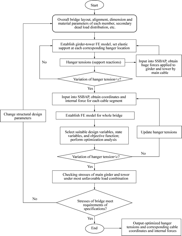
Fig. 3 Flowchart for determination of reasonable finished state of self-anchored suspension bridges
Step 1: Based on the overall bridge layout, main girder alignment, dead load distribution, dimension and material parameters of each bridge member, the girder- tower-only FE model is properly built, in which the effects of hanger and auxiliary pier on the main girder are simulated by elastic vertical support. The support reactions, which are predicted as the initial hanger tensions, are obtained from the model.
By changing the stiffness coefficient K, the stiffness proportion of each component (the main girder tower and the cable system) in the whole structural system could be adjusted according to the design intention. Schematic diagram of the elastic support system is plotted in Fig. 4, where Fig. 4(a) shows a continuous girder model with rigid support, which yields the largest support reactions at the corresponding hanger locations; Fig. 4(b) shows a girder model without mid-support, which has zero support reactions at the hanger locations; Fig. 4(c) shows a continuous girder model with elastic support, the reaction of which is between that of Figs. 4(a) and (b).
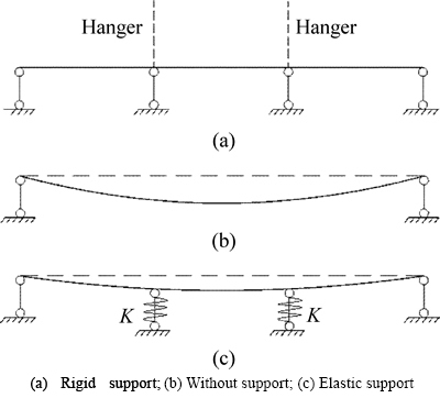
Fig. 4 Support schematic diagrams:
Step 2: Input the information of the initial hanger tensions from Step 1, and other pre-designed parameters (like the control point coordinates of the main cable, sag- to-span ratio, cable density, and hanger clamp weight) into the analytical cable program SSBAP, to calculate and obtain the huge forces applied to the girder and tower from the main cable. Then, these forces are put into the girder-tower-only FE model, and the procedure is repeated from Step 1 until the computed support reactions converge. Because the girder-tower-only FE model uses elastic supports to simulate relatively practical boundary conditions and takes the forces from main cable into consideration, generally, satisfactory results are obtained after 2 to 3 times of iterative computations.
Step 3: Input the converged hanger tensions from Step 2 into the SSBAP to obtain the initial configuration coordinates and internal force of each cable segment.
Step 4: Enter all the information of the main cable and each hanger (including the configuration coordinates and internal forces from Step 2 and Step 3) into the girder- tower-only FE model to establish a FE model of the whole bridge system.
It should be noted that for the case of a self- anchored suspension bridge, under the finished bridge state, the huge axial forces originated from the main cable would unavoidably compress the main girder and the tower. The deformations caused by the compression can result in changes of coordinates and internal forces of the main cable. In this work, during the FE model simulation, the ��temperature rigid arm��, which can pass the internal forces between joints, is introduced to offset the compression by adjusting its temperature. It has a linear temperature expansion coefficient, huge stiffness, and zero mass.
Step 5: By choosing the minimum strain energy of the stiffening girder and tower as objective function, hanger tensions as design variables and suitable state variables defined in Section 4.2.3, nonlinear analysis is repeated until the optimization process comes to an end and converges to a set of optimized hanger tensions.
Step 6: If the stresses of the main girder and tower under the most unfavorable load combination meet the relevant specification requirements, output the optimized set of hanger tensions, and the corresponding coordinates and forces of each cable segment by the FE model and SSBAP, respectively. Otherwise, change structural parameters and repeat this procedure from Step 1.
6 Examples of verification
6.1 Application to one simple tutorial example
Assume a small self-anchored suspension bridge, with an overall length of 70 m (10 m+20 m+30 m+10 m), as plotted in Fig. 5. There is one hanger (DS1) on the side span, and two hangers (DS2 and DS3) on the main span. The sag-to-span ratio is 1/12. Under the ideal finished bridge state, coordinates of each point are present in Table 1. Structural material and cross-section properties are given in Table 2. Girder alignment of the side span and anchoring span is horizontal, while alignment of the main span is a parabola curve, which can be determined from the following equation:
 (9)
(9)
This tutorial example aims at illustrating the realization process of the proposed procedure. The FE model is shown in Fig. 6, where Model 1 simulates the tower and girder system without hanger allocation;Model 2 is the FE model with hangers replaced by rigid supports at the corresponding hanger locations (Step 1 in Section 5); on the basis of Model 2, Model 3 applies the forces from the main cable to the tower top and the anchorage points, and converges to a set of initial hanger tensions or support reactions (Step 2 in Section 5); Model 4 is the optimized reasonable finished bridge state. Considering practical allocation of the hangers in this example, stiffness coefficient K is set to be infinite (Steps 3�C7 in Section 5). Table 3 lists the vertical support reactions and the strain energy of the Models 1�C4, respectively.
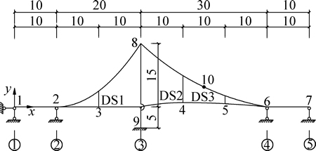
Fig. 5 Bridge dimensions (Unit: m)
Table 1 Coordinates under ideal finished bridge state (Unit: m)
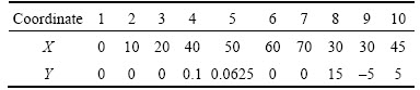
Table 2 Material and structural characteristic parameters
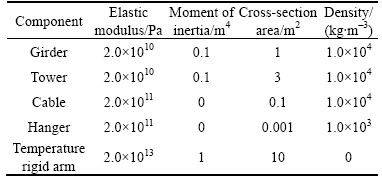
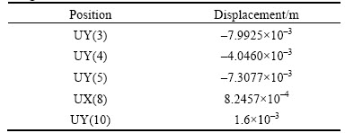
Table 4 lists the coordinates and internal forces of each cable segment of the side and main span in the reasonable finished bridge state. Note that the x-coordinates in the longitudinal direction are known parameters; values under columns Y1 and N1 are coordinates in the vertical direction and internal forces calculated from the FE model; values under columns Y2 and N2 are from the SSBAP. Due to the adoption of ��temperature rigid arm��, boundary conditions of the FE model and calculation conditions of SSBAP are in agreement. Thus, values from the FE model and SSBAP in Table 4 are pretty close. Also, displacements of the control points under the optimized reasonable finished bridge state are very small, as shown in Table 5, which verifies the effectiveness of the proposed procedure.
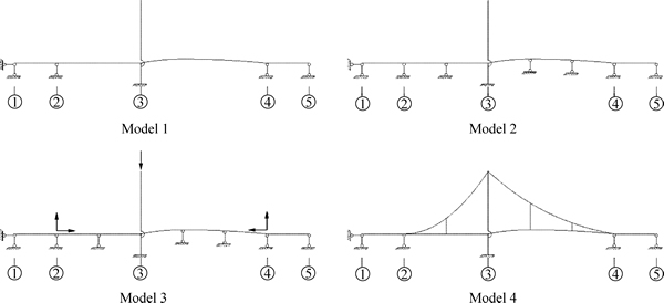
Fig. 6 FE models
Table 3 Vertical support reaction force and bending energy
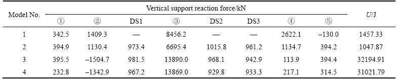
Table 4 Coordinates and internal forces of main cable in reasonable finished bridge state
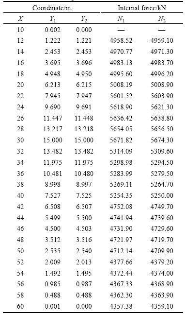
Table 5 Displacements of control points in reasonable finished bridge state
6.2 Application to Jiangxinzhou self-anchored suspension bridge
6.2.1 Bridge description
The Jiangxinzhou Bridge is one of several new bridges over the Yangtze River in Nanjing, China, which was completed and opened to traffic in June, 2010. The bridge is a 5-span self-anchored suspension bridge with an overall length of 550 m (35 m+77 m+60 m+248 m+ 35 m). Its main span of 248 m is one of the longest spans among the completed self-anchored suspension bridges that have a single tower and a spatial cable shape in China. The bridge has 6 lanes that carry two road ways 25.1 m wide. The height of the main tower is 112 m. Figure 7 shows a schematic representation of the bridge with plan, elevation and typical cross sectional views. There are 12 hangers (DS1�CDS12) on the side span, and 21 hangers (DS13�CDS33) on the main span. Jiangxinzhou Bridge has complex structure and multitudinous parameters. Structural characteristic parameters of typical cross-sections are listed in Table 6.
6.2.2 Finite element model
A three-dimensional finite element model shown in Fig. 8 was established for the Jiangxinzhou Bridge [6].The tower and the girder are modeled by three- dimensional beam elements, while the main cables and hangers by three-dimensional link element accounting for geometric nonlinearity due to the cable sag. The bridge deck is represented by a single beam and the cross-sectional properties of the bridge deck are assigned to the beam as equivalent properties. The connections between hangers and the girder are simulated by special rigid elements, which have huge stiffness with zero mass. The other connections between bridge components and the supports of the bridge are properly modeled. The whole finite element model, as shown in Fig. 8, consists of 838 beam elements, 201 link elements, and 718 nodes, where 800 beam elements are for the girder and 38 beam elements for the tower.
6.2.3 Results for reasonable finished bridge state
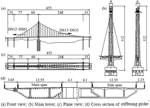
Fig. 7 Structural dimensions of Jiangxinzhou Bridge (Unit: m):
Table 6 Structural characteristic parameters of Jiangxinzhou Bridge
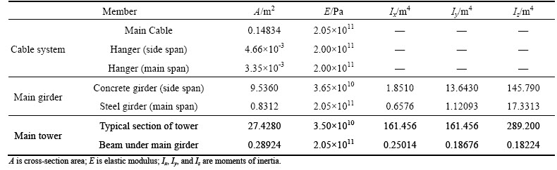
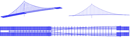
Fig. 8 Spatial FE model of Jiangxinzhou Bridge
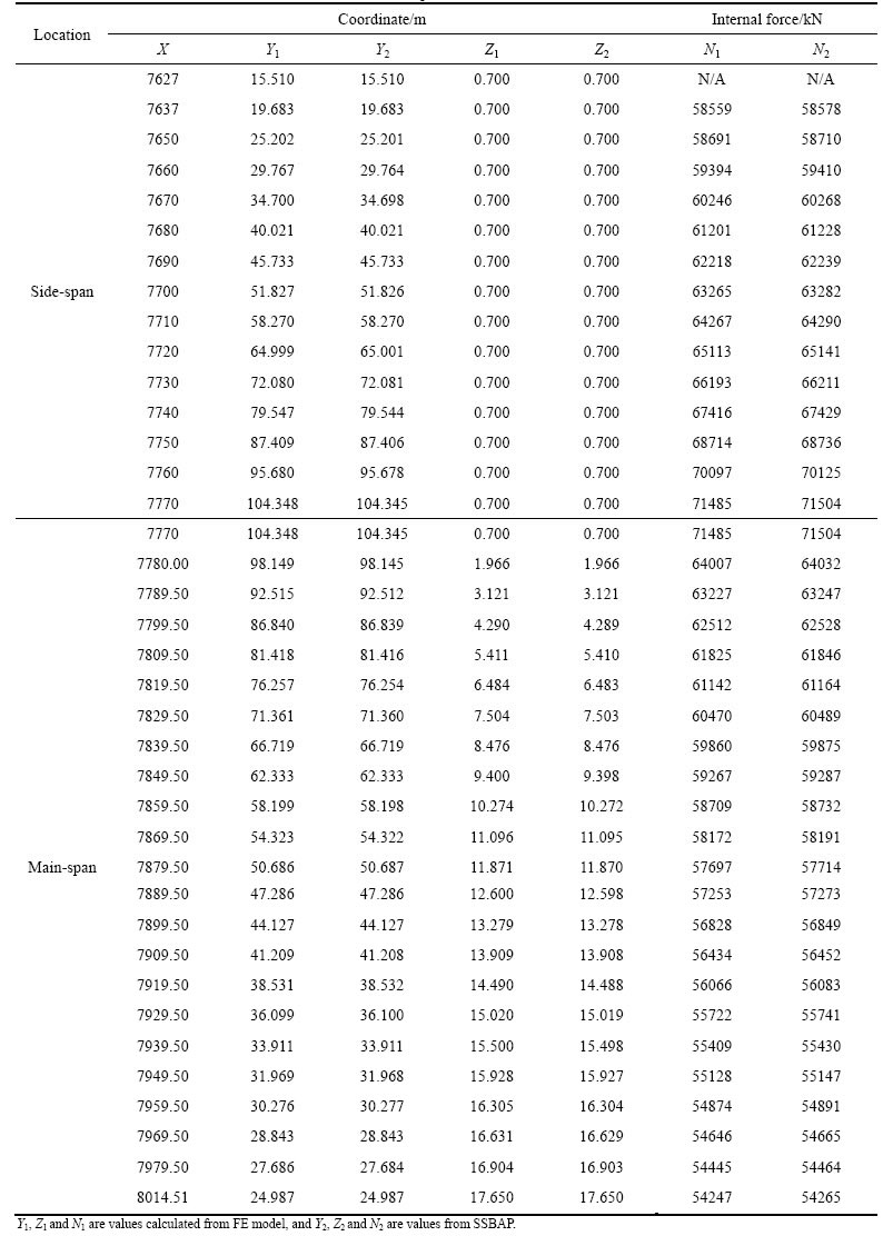
The proposed procedure is applied to the determination of the reasonable finished bridge state of Jiangxinzhou bridge. Three-dimensional coordinates (plotted in Fig. 9) and Table 7 lists the optimized set of hanger tensions. The internal forces of the cable segment from the analytical program SSBAP and those from the FE model under the optimized finished bridge state are compared in Table 8. Note that the x-coordinates in the longitudinal direction are known parameters; the y-coordinates refer to the vertical position of each cable segment; the z-coordinates are related to the lateral position. Again, due to the adoption of ��temperature rigid arm��, the boundary conditions of the FE model and the calculation conditions of SSBAP are in agreement. It improves the accuracy of the proposed procedure.
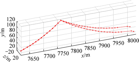
Fig. 9 Three-dimensional plot of cable coordinates
Table 7 Hanger force under finished condition
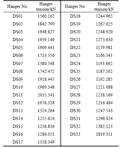
Table 8 Coordinates and internal forces of main cable of side span
7 Conclusions
A systematic and generic procedure is proposed for the determination of the reasonable finished state of self- anchored suspension bridges. By combining analytical cable program with the girder-tower-only FE model, the initial hanger tensions are first obtained through an iterative analysis. Then, the initial hanger tensions, the corresponding cable coordinates and internal forces are included into the FE model of the total bridge system. Nonlinear analysis is repeated until the optimization process converges to the best hanger tensions. The effectiveness of the proposed method is demonstrated by a numerical example and a spatial cable self-anchored suspension bridge.
Three marked characteristics of the proposed approaches are: 1) By choosing the minimum strain energy of the stiffening girder and tower as objective function, hanger tensions as design variables and suitable state variables, structural optimization technique is introduced to find a set of optimal hanger tensions for the reasonable finished bridge state; 2) The girder-tower- only FE model is used to obtain the initial hanger tensions. By changing the stiffness coefficient K, the stiffness proportion of the tower, the main girder or the cable system in the whole structural system could be adjusted according to the design intentions; 3) Due to the adoption of ��temperature rigid arm�� to offset the unavoidable initial deformations of the stiffening girder and the tower, calculation conditions of FE model and the analytical program SSBAP are in agreement, which further improves the accuracy of the proposed procedure.
References
[1] GIL H, CHO C. Yong Jong grand suspension bridge, Korea [J]. Structural Engineering International, IABSE, 1998, 8(2): 97�C98.
[2] KIM H K, LEE M J, CHANG S P. Non-linear shape-finding analysis of a self-anchored suspension bridge[J]. Engineering Structures, 2002, 24: 1547�C1559.
[3] SUN J, MANZANAREZ R, NADER M. Design of looping cable anchorage system for new San Francisco-Oakland Bay bridge main suspension span [J]. J Bridge Eng, 2002, 7(6): 315�C324.
[4] LI Chuan-xi, KE Hong-jun, LIU Hai-bo, XIA Gui-yun. Determination of finished bridge state of self-anchored suspension bridge with spatial cables [J]. Engineering Mechanics, 2010, 27(5): 137�C146. (in Chinese)
[5] ZHANG J, LIU A, MA Z, HUANG H, MEI L, LI Y. Behavior of self-anchored suspension bridges in the structural system transformation [J].J Bridge Eng,2013, 18(8): 712�C721.
[6] LI J H, LI A Q, FENG M Q. Sensitivity and reliability analysis of a self-anchored suspension bridge [J]. J Bridge Eng, 2013, 18(8): 703�C711.
[7] CHEN D W, AU F T K, THAM L G, LEE P K K. Determination of initial cable forces in prestressed concrete cable-stayed bridges for given design deck profiles using the force equilibrium method [J]. Computers & Structures, 2000, 74: 1�C9.
[8] WANG P H, TSENGT C, YANG C G. Initial shape of cable-stayed bridges [J]. Computers & Structures, 1993, 47: 111�C123,.
[9] KIM K S, LEE H S. Analysis of target configurations under dead loads for cable-supported bridges [J]. Computers & Structures, 2001, 79: 2681�C2692.
[10] LI J H, LI A Q, YUAN H H. Calculation method of spatial cable curve for single-pylon self-anchored suspension bridge [J]. Journal of Highway and Transportation Research and Development, 2009, 26(10): 66�C70. (in Chinese)
[11] HAN Y, CHE Z Q, LUO S D, YANG S K. Calculation method on shape finding of self-anchored suspension bridge with spatial cables [J]. Front Archit Civ Eng China, 2009, 3(2): 165�C172.
[12] IMO I I, LEECH D J. Discontinuous optimization in batch production using SUMT [J]. Int J Prod Res, 1984, 22(2): 313�C321.
[13] DAI Y H. Convergence properties of the BFGS algorithm [J]. Siam J Optim, 2002, 13(3): 693�C701.
(Edited by YANG Bing)
Foundation item: Project(20133204120015) supported by Specialized Research Fund for the Doctoral Program of Higher Education of China; Project(12KJB560003) supported by the Natural Science Foundation of the Higher Education Institution of Jiangsu Province, China
Received date: 2014-11-24; Accepted date: 2015-04-10
Corresponding author: FENG Dong-ming, PhD Candidate; Tel: +1�C9178344717; E-mail: df2465@columbia.edu

