Trans. Nonferrous Met. Soc. China 23(2013) 412-419
Microarc oxidation coating fabricated on AZ91D Mg alloy in an optimized dual electrolyte
Shu-yan WANG1, 2, Yong-ping XIA1
1. School of Materials Science and Engineering, Jiangsu University of Science and Technology, Zhenjiang 212003, China;
2. Provincial Key Lab of Advanced Welding Technology, Jiangsu University of Science and Technology, Zhenjiang 212003, China
Received 14 November 2011; accepted 26 April 2012
Abstract: Microarc oxidation (MAO) process was conducted on AZ91D magnesium alloy in an electrolyte composed of Na2SiO3, NaAlO2, Na2B4O7, NaOH, C3H8O3 and C6H5Na3O7 by AC pulse electrical source. The surface and cross-sectional morphologies, film thickness, chemical composition and structure of the coatings were characterized by scanning electron microscopy(SEM), layer thickness metry, energy disperse spectroscopy(EDS) and X-ray diffraction(XRD). The corrosion resistances of the coatings in a 3.5% NaCl neutral solution were evaluated by electrochemical impedance spectroscopy (EIS) and potentiodynamic polarization test. The results showed that an optimized electrolyte with a composition of 15 g/L Na2SiO3, 9 g/L NaAlO2, 2 g/L Na2B4O7, 3 g/L NaOH, 5 mL/L C3H8O3 and 7 g/LC6H5Na3O7 was developed by means of orthogonal experiment. The coating obtained in the optimized electrolyte had a dense structure and revealed a lower current density, decreased by two orders of magnitude as compared with the magnesium substrate. Meanwhile, the corrosive potentials of the coated samples increased nearly by 73 mV. EIS result showed that the corrosion resistance of the coating was mainly determined by the inner dense layer. The coating primarily contained elements Mg, Al, O and Si and XRD analyses indicated that the coating was mainly composed of MgO, Mg2SiO4 and MgAl2O4.
Key words: magnesium alloy; microarc oxidation; dual electrolyte; corrosion resistance
1 Introduction
Owing to the high specific strength, good electromagnetic shielding and recycling ability, magnesium alloys are widely used in aerospace, automobile and communication industries [1,2]. However, magnesium alloys exhibit a poor corrosion resistance because of the high chemical activity of the magnesium and this disadvantage has restricted their wide applications in many situations, especially in the aggressive environment [3]. In order to improve the corrosion resistance, a lot of surface modification techniques have been applied to magnesium alloys, including chemical conversion coating [4], electrochemical plating conversion coating [5], anodizing [6] and microarc oxidation [7]. Among these surface treatment methods, MAO is a new surface modification technique of forming ceramic coatings on light metals such as Al, Ti, Mg and its alloys. The corrosion and wear resistance can be remarkably enhanced after the MAO process [8,9].
As is well known, the characteristics of the MAO coatings mainly depend on the nature of substrate, the applied electrical parameter, the composition and concentration of the electrolyte, etc [10-13]. Among these parameters, the composition of the electrolyte plays an important role in the characteristics of the coatings due to the incorporation of the elements in the electrolyte into the substrate during the MAO process [14]. In recent years, the weak alkaline electrolyte such as silicate, aluminate and phosphate systems have been widely used as the base electrolyte. Moreover, some additives such as tungstate, fluorite, glycerol and various nanoparticles are added into the base electrolyte to obtain the coatings with good performances [15-18].
It is considered that mixture of more than one electrolyte will improve the microstructure and performance of the MAO coatings. However, a systematic study about the effects of dual or multiple electrolytes on the MAO coatings has not been well documented in literatures. In this work, a dual electrolyte system consisting of silicate (Na2SiO3) and aluminate (NaAlO2) as well as the additives of Na2B4O7, NaOH, C3H8O3 and C6H5Na3O7 was used to develop the coatings with good corrosion resistance on AZ91D magnesium alloy under constant current mode. The aim is to optimize the concentration of each element in the electrolyte solution by means of orthogonal experiment, and then study the growth characteristic, microstructure, phase, elemental composition and corrosion resistance of the coating fabricated on AZ91D magnesium alloy.
2 Experimental
Rectangular samples (15 mm��15 mm��5 mm) of AZ91D magnesium alloy (8.91% Al, 0.23% Mn, 0.54% Zn, 0.0011% Be, 0.002% Cu, 0.0014% Fe, 0.0005% Ni, 0.034% Si, Mg balance in mass fraction) were used as substrates in the experiment. Prior to MAO treatment, the samples were polished with various grades of silicon carbide waterproof abrasive paper from 600 to 2000 grits, and then ultrasonically cleaned in ethanol and distilled water.
WHD-20 MAO system with a pulsed bipolar AC power supply, a stainless steel bath used as the counter electrode and a stirring and cooling system keeping the electrolyte temperature below 40 ��C was used for the MAO process. The experiments were carried out under constant current mode and the anodic and cathodic current densities were fixed at 10 and 12 A/dm2, respectively. The duty cycle of both pulses was equal to 30%. The samples were treated for 15 min with a frequency of 700 Hz. The dual electrolyte system used for the orthogonal experiment was prepared from distilled water containing 13-17 g/L Na2SiO3, 9-15 g/L NaAlO2, 2-4 g/L Na2B4O7, 1-3 g/L NaOH, 3-7 mL/L C3H8O3 and 3-7 g/L C6H5Na3O7. The orthogonal experiment was used in order to obtain an optimized electrolyte.
The thickness of the coatings was assessed using a layer thickness meter. The surface and cross-sectional morphologies of the coatings were observed using a scanning electron microscope (SEM, JSM-6480). The composition of the coatings was characterized by an energy disperse spectroscope (EDS). The structure was examined by X-ray diffraction (XRD-6000) operating with Cu K�� radiation.
Electrochemical impedance spectroscopy (EIS) and potentiodynamic polarization test were performed using the M283 electrochemical measurement system containing a potentiostat and a lock-in amplifier in 3.5% NaCl (pH=7) solution. The signal of EIS was 10 mV and the frequency ranged from 105 Hz to 10-1 Hz. The potentiodynamic polarization test was carried out with a scanning rate of 1 mV/s and a scanning ranging from -250 mV to +250 mV vs open circuit potential. All electrochemical measurements were performed with a conventional three-electrode cell consisting of a platinum electrode as the counter electrode, a saturated calomel electrode as the reference electrode and the coated samples as the working electrode.
3 Results and discussion
3.1 Orthogonal experiment and analysis
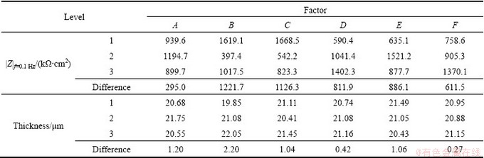
In the present work, the orthogonal experiment of six factors including Na2SiO3 concentration, NaAlO2 concentration, Na2B4O7 concentration, NaOH concentration, C3H8O3 concentration and C6H5Na3O7 concentration with three levels was used to comprehensively investigate the effects of concentration of each element in the electrolyte on the corrosion resistance and thickness of coatings fabricated on AZ91D magnesium alloys. The concentrations of Na2SiO3, NaAlO2, Na2B4O7, C6H5Na3O7, C3H8O3 and NaOH were marked by A, B, C, D, E and F, respectively. The orthogonal experimental array and experimental results are listed in Table 1. In order to systematically investigate the effects of each factor on the characteristics of the coating, the experimental data were treated by the method of variation analysis. The maximum difference between the average data at two levels for each factor indicated the remarkable effect of that factor. The value of the impedance in low frequency (e.g., 10-1 Hz) can be considered an indication of the corrosion resistance (R, approximately equal to |Z|f=0.1 Hz) of the coatings [19]. Consequently, the corrosion resistances of the coatings were determined from the magnitude of the impedance data at 0.1 Hz. Based on the differences, the effect order of factors on the impedance (|Z|f=0.1 Hz) of the coatings could be found. It was obvious that the NaAlO2 concentration was the major factor affecting the impedance, which is listed in Table 2. The decreasing sequence of factors affecting the impedance of the coatings was Na2B4O7 concentration, C3H8O3 concentration, NaOH concentration, C6H5Na3O7 concentration and Na2SiO3 concentration. Similarly, the data about the coating thickness were dealt by the same method as the corrosion resistance and it was easy to find that the NaAlO2 concentration was also the major factor affecting the coating thickness, as shown in Table 2. The decreasing sequence of factors affecting the coating thickness of the coatings was Na2SiO3 concentration, C3H8O3 concentration, Na2B4O7 concentration, C6H5Na3O7 concentration and NaOH concentration. Because the impedance (|Zf=0.1Hz) was the main evaluation index to select the optimized level of each factor, the constitutes of the optimized electrolyte (marked by a symbol * in Table 1)was 15 g/L Na2SiO3, 9 g/L NaAlO2, 2 g/L Na2B4O7, 7 g/L C6H5Na3O7, 5 mL/L C3H8O3 and 3 g/L NaOH.
Table1 Results of orthogonal experiment
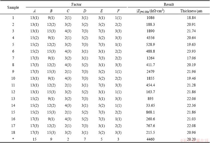
Table 2 Variation analysis of orthogonal experiments
3.2 Growth characteristic
The voltage��time response for microarc oxidation of Mg alloy in the optimized dual electrolyte is shown in Fig. 1, which displays three regions. In the first region, stage I (0-73 s), the voltage increased linearly with time at a slope of 3.29 V/s, indicating the formation of anodic oxidation. Meanwhile, a slightly thin dielectric film began to form on the surface of Mg alloy during the initial stage, which resulted in the rapid raising of voltage [20]. After the initial stage, the voltage continually increased with time, but the voltage��time response decreased to 0.66 V/s in stage II (73-284 s), and a large number of silvery white sparks with small size distributed evenly over the whole surface of the sample when the cell voltage reached breakdown voltage (240 V). CHANG [21] showed that the total current density consisted of the ionic current density and the electron current density; in the first region, the current was only represented by the ionic current, but the total current in the second region was represented by the sum of the ionic current and electron current caused by the sparking; so a relatively low voltage was needed to maintain the same current compared with the first region. In the third region, stage III (284-900 s), the voltage��time response slop dropped rapidly, close to 0, indicating that the cell voltage reached a relatively stable value, meanwhile, white sparks changed to a lot of separate orange ones which moved slowly across the surface.
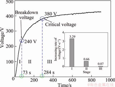
Fig. 1 Voltage��time responses for microarc oxidation process
3.3 Surface and cross-sectional morphology
The surface and cross-sectional morphologies of the coating obtained in the optimized electrolyte are shown in Fig. 2. Typical porous coating surface was obtained, and there were many micropores (marked by arrow 1) and some micro-cracks (marked by arrow 2) on the surface of the coating, as shown in Fig. 2(a). Micropores were formed by the molten oxide and gas bubbles thrown out of microarc discharge channels, while the appearance of micro-cracks resulted from thermal stress owing to the rapid solidification of molten oxide in the relatively cool electrolyte [22]. Furthermore, the width of micro-cracks was small and the size of the micropores (Fig. 2(a)) was less than 3.2 ��m, indicating a dense and smooth surface of the coating, which can prevent the corrosive medium from penetrating into the magnesium alloy effectively. The cross-sectional morphology in Fig. 2(b) showed that the coating was characterized with a typical outer loose layer and inner dense layer, also with some micropores (marked by arrow 3) and tiny micro-cracks (marked by arrow 4) in the cross-sections. However, these micropores and micro-cracks did not connect with each other and penetrate through the whole coating.
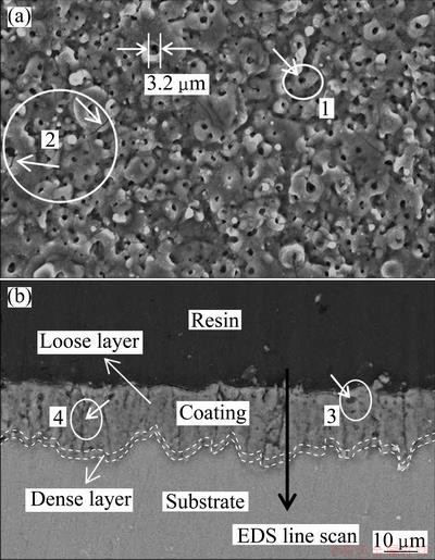
Fig. 2 Surface (a) and cross-sectional (b) morphologies of coating obtained in optimized electrolyte

Fig. 3 XRD pattern of optimized MAO coating
3.4 Phase and elemental compositions
Figure 3 shows the X-ray diffraction pattern of the coating obtained in the optimized electrolyte. It can be concluded that the coating was mainly composed of MgO, Mg2SiO4 and MgAl2O4. The intensities of peaks corresponding to the substrate were very strong, suggesting that X-ray can easily penetrate through the coating and reach the substrate. The formation mechanism of the phases may be described according to the chemical reaction formulas (1)-(6) as follows:
Mg-2e��Mg2+ (1)
 ��
�� (2)
(2)
Mg2++2OH-��Mg(OH)2 (3)
Mg(OH)2��MgO+H2O (4)
Mg2++2[Al(OH)4]-��MgAl2O4+4H2O (5)
(n+2)Mg2++2[Aln(OH)4n+2](n+2)-��nMgAl2O4+2Mg(OH)2+4NH2O (6)
During the MAO process, negative ions  and OH- were pushed forward towards the molten substrate by the force of electric field, and a chemical reaction occurred among , OH- and Mg2+, and then transformed into Mg2SiO4 phase. Moreover, the formation of MgO phase was due to the dehydration of Mg(OH)2 because of the high temperature during the sparking discharge process [23]. YEROKHIN et al [24] reported that complex-ion [Al(OH)4]- or [Aln(OH)4n+2](n+2)- existed in the electrolyte instead of
  anion. The presence of MgAl2O4 phase was due to the reaction between Mg2+ and [Al(OH)4]- or [Aln(OH)4n+2](n+2)-.
Figure 4 represents the cross-sectional elements distribution of the optimized MAO coating detected by EDS line scan. It was found that the optimized MAO coating mainly contained Mg, Al, O and Si elements. The distributions of Mg and O were similar, which exhibited relative concentrations in the out loose layer and inner dense layer. The concentrations of Al and Si in the outer loose layer were higher than those in the inner dense layer, which showed MgAl2O4 and Mg2SiO4 phase mainly distributed in the outer loose layer. The diffusion resistance of , [Al(OH)4]- and [Aln(OH)4n+2](n+2)- anions transport in the inner layer was stronger than that in the outer layer, so the concentrations of Al and Si elements in the inner layer were less than those in the outer layer. In a word, from Fig. 3 and Fig. 4, it can be inferred that MgAl2O4 and Mg2SiO4 phases mainly distributed in the outer loose layer; MgO phase evenly distributed in the whole coating.
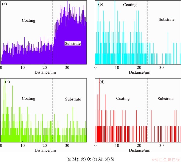
Fig. 4 Cross-sectional element distribution of optimized MAO coating detected by EDS
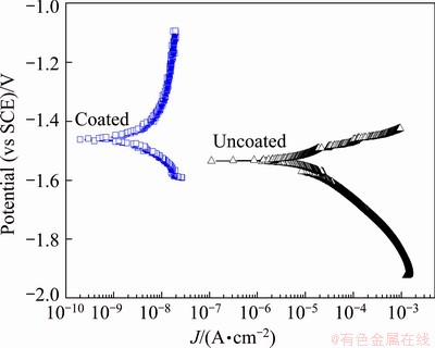
Fig. 5 Potentiodynamic polarization curves of AZ91D alloy with and without coating in 3.5% NaCl solution
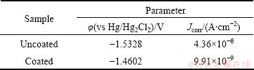
Table 3 Fitted electrochemical parameters from potentio- dynamic polarization curves
3.5 Corrosion resistance
Figure 5 demonstrates the polarization curves of the coating formed in the optimized electrolyte. The polarization curve of the substrate is also given in this figure. The corrosion potential and corrosion current density derived from the polarization curves by way of Tafel fitting using the software named Corrview in Fig. 5 are listed in Table 3. The corrosion potential and corrosion current density of coated samples are often used to characterize the corrosion resistance of the coating. The higher corrosion potential and lower corrosion current density suggest that it exhibits a good corrosion resistance. Similarly, it was obvious that the coated sample exhibited a more positive corrosion potential and a lower corrosion current density than the magnesium alloy substrate. The corrosion potential of the coated sample increased nearly by 73 mV, while the corrosion current density decreased by more than two orders of magnitude compared with the substrate. This demonstrated that the coating formed in the optimized electrolyte could provide an effective corrosion protective property for the substrate. The excellent corrosion resistance of the coating may be due to its relatively uniform and compact microstructure as well as its stable chemical thermodynamic compositions, as shown in Fig. 2 and Fig. 3.
Electrochemical impedance spectroscopy (EIS) was employed to investigate the corrosion characteristics of the MAO coating fabricated on AZ91D Mg alloy in the optimized electrolyte. The radius of the capacitive loop represents the corrosion resistance of the coating. As shown in Fig. 6, the coating obtained in the optimized electrolyte exhibited a much larger capacitive loop, indicating that it provided a better effective corrosion protection as compared with magnesium substrate. Moreover, from the partial enlarged detail in Fig. 6(a), the appearance of inductive loop indicated that the corrosive medium (e.g., Cl-1) had already induced the corrosion of substrate [20], which proved that pitting occurred on the surface of magnesium substrate easily. Based on the characteristics of corrosive process in the electrochemical reaction system, an appropriate equivalent circuit employed for curve fitting of the MAO optimized coating is illustrated in Fig. 7. The indicated equivalent circuit gave the best fitting results with the lowest error. As shown in Fig. 7, the equivalent circuit for the MAO optimized coating consisting of two time constants exhibits two different resistances in the coating, namely the outer loose layer and inner dense layer. Rs, R1 and R2 represent the resistance of the solution, the outer loose layer and inner layer, respectively. Constant phase elements (CPE) were used in the electrochemical circuit instead of capacitors in order to account for the surface heterogeneity and diffusion factors, and the admittance of CPE is expressed as following formula [25]:
 (7)
(7)
where T is CPE constant; j is the imaginary unit; �� is the angular frequency; n is the CPE exponent. According to the value of n, CPE can represent resistance when n=0, capacitance when n=1 and Warburg impedance when n=0.5. In Fig. 7, CPE1 and CPE2 represent the capacitances of the outer loose layer and inner layer, respectively. Figure 6 demonstrates the experimental and fitted results. Moreover, the corresponding fitted data are listed in Table 4. As shown in Fig. 2(a) above, the MAO coating exhibited a porous surface and there were some micro-cracks on the surface of the coating, therefore, the value of R1 was low. The obtained data of R1 and R2 are 6.782��104 and 6.454��106 ����cm2, respectively. Therefore, a low R1 and a much higher R2 value exhibited that the outer loose layer was not able to provide high resistance against the corrosion and the corrosion resistance of the coating was mainly determined by the inner dense layer.
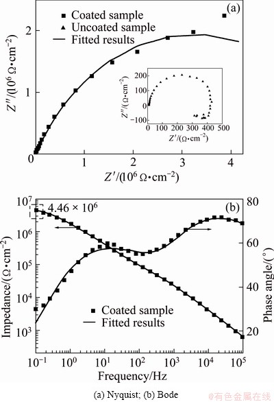
Fig. 6 Electrochemical impedance behaviors of coated sample and uncoated sample
Table 4 Data of equivalent circuits of coated sample

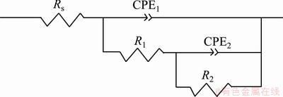
Fig. 7 Equivalent circuits for fitting experimental data of coated sample
4 Conclusions
1) An optimized electrolyte containing 15 g/L Na2SiO3, 9 g/L NaAlO2, 2 g/L Na2B4O7, 3 g/L NaOH, 5 mL/L C3H8O3 and 7 g/L C6H5Na3O7 is developed.
2) The MAO process is divided into three stages according to the voltage��time response. The coating formed in the optimized electrolyte exhibits a top porous surface with some micro-cracks, but both the size of the micropores and the width of micro-cracks are small. The mean coating thickness is 20.2 ��m and the coating is compact and uniform to be seen in the cross-sections. Moreover, the optimized coating primarily contains Mg, Al, O and Si elements and is mainly composed of MgO, Mg2SiO4 and MgAl2O4 phases.
3) According to the results of EIS and potentiodynamic polarization test, the coating obtained in the optimized electrolyte demonstrates an effective protection for the magnesium substrate. Compared with the substrate, the corrosive potential of the coated samples increased nearly by 73 mV, while the corrosion current density decreased by two orders of magnitude. Electrochemical impedance spectroscopy data of R1 and R2 are 6.782��104 and 6.454��106 ����cm2, indicating that the corrosion resistance of the coating was mainly determined by the inner dense layer.
References
[1] CATON P D. Magnesium��An old material with new applications [J]. Materials & Design, 1991, 12(6): 309-316.
[2] MORDIKE B L, EBERT T. Magnesium: Properties-applications- potential [J]. Materials Science and Engineering A, 2001, 302(1): 37-45.
[3] GRAY J E, LUAN B. Protective coatings on magnesium and its alloys��A critical review [J]. Journal of Alloys and compounds, 2002, 336(1-2): 88-113.
[4] YANG K H, GER M D, HWU W H, SUNG Y, LIU Y C. Study of vanadium-based chemical conversion coating on the corrosion resistance of magnesium alloy [J]. Materials Chemistry and Physics, 2007, 101(2-3): 480-485.
[5] WU Li-ping, ZHAO Jing-jing, XIE Yong-ping, YANG Zhong-dong. Progress of electroplating and electroless plating on magnesium alloy [J]. Transactions of Nonferrous Metals Society of China, 2010, 20(s2): s630-s637.
[6] LIU Yan, WEI Zhong-ling, YANG Fu-wei, ZHANG Zhao. Environmental friendly anodizing of AZ91D magnesium alloy in alkaline borate-benzoate electrolyte [J]. Journal of Alloys and Compounds, 2011, 509(22): 6440-6446.
[7] YEROKHIN A L, NIE X, LEYLAND A, MATTHEWS A, DOWEY S J. Plasma electrolysis for surface engineering [J]. Surface and Coatings Technology, 1999, 122(2-3): 73-93.
[8] LIANG J, SRINIVASAN P B, BLAWERT C, DIETZEL W. Comparison of electrochemical corrosion behaviour of MgO and ZrO2 coatings on AM50 magnesium alloy formed by plasma electrolytic oxidation [J]. Corrosion Science, 2009, 51(10): 2483-2492.
[9] SRINIVASAN P B, BLAWERT C, DIETZEL W. Dry sliding wear behaviour of plasma electrolytic oxidation coated AZ91 cast magnesium alloy [J]. Wear, 2009, 266(11-12): 1241-1247.
[10] CAKMAK E, TEKIN K C, MALAYOGLU U, SHRESTHA S. The effect of substrate composition on the electrochemical and mechanical properties of PEO coatings on Mg alloys [J]. Surface and Coatings Technology, 2010, 204(8): 1305-1313.
[11] TANG Yu-ming, ZHAO Xu-hui, JIANG Kui-sheng, CHEN Jun, ZUO Yu. The influences of duty cycle on the bonding strength of AZ31B magnesium alloy by microarc oxidation treatment [J]. Surface and Coatings Technology, 2010, 205(6): 1789-1792.
[12] GNEDENKOV S V, KHRISANFOVA O A, ZAVIDNAYA A G, SINEBRYUKHOV S L, EGORKIN V S, NISTRATOVA M V, YEROKHIN A, MATTHEWS A. PEO coatings obtained on an Mg�CMn type alloy under unipolar and bipolar modes in silicate-containing electrolytes [J]. Surface and Coatings Technology, 2010, 204(14): 2316-2322.
[13] ZHANG R F, ZHANG S F, DUO S W. Influence of phytic acid concentration on coating properties obtained by MAO treatment on magnesium alloys [J]. Applied Surface Science, 2009, 255(18): 7893-7897.
[14] LUO Hai-he, CAI Qi-zhou, WEI Bo-kang, YU Bo, LI Ding-jun, HE Jian, LIU Ze. Effect of (NaPO3)6 concentrations on corrosion resistance of plasma electrolytic oxidation coatings formed on AZ91D magnesium alloy [J]. Journal of Alloys and Compounds, 2008, 464(1-2): 537-543.
[15] ZHAO Fang, LIAO Ai-di, ZHANG Rong-fa, ZHANG Shu-fang, WANG Hai-xia, SHI Xing-mei, LI Ming-jie, HE Xiang-ming. Effects of sodium tungstate on properties of micro-arc coatings on magnesium alloys [J]. Transactions of Nonferrous Metals Society of China, 2010, 20(s2): s683-s687.
[16] WANG Li, CHEN Li, YAN Zong-cheng, WANG Hong-lin, PENG Jia-zhi. Effect of potassium fluoride on structure and corrosion resistance of plasma electrolytic oxidation films formed on AZ31 magnesium alloy [J]. Journal of Alloys and Compounds, 2009, 480(2): 469-474.
[17] WU Di, LIU Xiang-dong, LU Kai, ZHANG Ya-ping, WANG Huan. Influence of C3H8O3 in the electrolyte on characteristics and corrosion resistance of the microarc oxidation coatings formed on AZ91D magnesium alloy surface [J]. Applied Surface Science, 2009, 255(16): 7115-7120.
[18] LEE K M, SHIN K R, NAMGUNG S, YOO B, SHIN D H. Electrochemical response of ZrO2-incorporated oxide layer on AZ91 Mg alloy processed by plasma electrolytic oxidation [J]. Surface and Coatings Technology, 2011, 205(13-14): 3779-3784.
[19] LIANG J, SRINIVASAN P B, BLAWERT C, DIETZEL W. Influence of pH on the deterioration of plasma electrolytic oxidation coated AM50 magnesium alloy in NaCl solutions [J]. Corrosion Science, 2010, 52(2): 540-547.
[20] LIU Feng, SHAN Da-yong, SONG Ying-wei, HAN En-hou. Formation process of composite plasma electrolytic oxidation coating containing zirconium oxides on AM50 magnesium alloy [J]. Transactions of Nonferrous Metals Society of China, 2011, 21(4): 943-948.
[21] CHANG Li-min. Growth regularity of ceramic coating on magnesium alloy by plasma electrolytic oxidation [J]. Journal of Alloys and Compounds, 2009, 468(1-2): 462-465.
[22] DUAN Hong-ping, YAN Chuan-wei, WANG Fu-hui. Effect of electrolyte additives on performance of plasma electrolytic oxidation films formed on magnesium alloy AZ91D [J]. Electrochimica Acta, 2007, 52(11): 3785-3793.
[23] MA Y, NIE X, NORTHWOOD D O, HU H. Systematic study of the electrolytic plasma oxidation process on a Mg alloy for corrosion protection [J]. Thin Solid films, 2006, 494(1-2): 296-301.
[24] YEROKHIN A L, LEYLAND A, MATTHEWS A. Kinetic aspects of aluminium titanate layer formation on titanium alloys by plasma electrolytic oxidation [J]. Applied Surface Science, 2002, 200(1-4): 172-184.
[25] SRINIVASAN P B, LIANG J, BLAWERT C,  M, DIETZEL W. Effect of current density on the microstructure and corrosion behaviour of plasma electrolytic oxidation treated AM50 magnesium alloy [J]. Applied Surface Science, 2009, 255(7): 4212-4218.
���Ż���˫���Һ�Ʊ�AZ91Dþ�Ͻ�������Ĥ
������1,2������ƽ1
1. ���տƼ���ѧ ���Ͽ�ѧ�빤��ѧԺ���� 212003��
2. ���տƼ���ѧ ����ʡ�Ƚ����Ӽ����ص�ʵ���ң��� 212003
ժ Ҫ���ں���Na2SiO3��NaAlO2��Na2B4O7��NaOH��C3H8O3��C6H5Na3O7�ĵ��Һ�У����ý��������Դ��AZ91Dþ�Ͻ��������������������SEM��Ĥ�����ǡ�EDS��XRD�ֱ��о�Ĥ��ı���ͽ�������ò����ȡ��ɷּ���ṹ�����ý����迹�Ͷ���λ���������������Ĥ����3.5%NaCl������Һ�е���ʴ���ܡ������������������õ���˫���Һ�ɷ�Ϊ15 g/L Na2SiO3��9 g/L NaAlO2��2 g/L Na2B4O7�� 3 g/L NaOH�� 5 mL/L C3H8O3 ��7 g/L C6H5Na3O7�������������������õ���Ĥ������ܣ��丯ʴ�����ܶȽ�þ�Ͻ����Ľ�����2�����������Ը�ʴ��λ����˽�73 mV��EIS�����ΪĤ�����ʴ��ȡ�����ڲ����ܲ㡣������Ĥ��Ҫ���Ԫ��ΪMg��Al��O��Si����Ҫ�����ΪMgO��Mg2SiO4��MgAl2O4��
�ؼ��ʣ�þ�Ͻ���������˫���Һ����ʴ��
(Edited by Hua YANG)
Foundation item: Project (12504230006) supported by the Priority Academic Program Development of Jiangsu Higher Education Institutions, China
Corresponding author: Shu-yan WANG; Tel: +86-511-84426291; E-mail: wsy101010@126.com
DOI: 10.1016/S1003-6326(13)62478-4

