J. Cent. South Univ. Technol. (2009) 16: 0608-0613
DOI: 10.1007/s11771-009-0101-8

Control strategy for pneumatic rotary position servo systems based on feed forward compensation pole-placement self-tuning method
MAO Xin-tao(毛新涛), YANG Qing-jun(杨庆俊), WU Jin-jun(吴晋军), BAO Gang(包 钢)
(Pneumatic Center, Harbin Institute of Technology, Harbin 150001, China)
Abstract: The pneumatic rotary position system, in which an electro-pneumatic proportional flow valve controled a rotary cylinder, was studied, and its mathematical model was built. The model indicated that the controlled pneumatic system had disadvantages such as inherent non-linearity and variations of system parameters with working points. In order to improve the dynamic performance of the system, feed forward compensation self-tuning pole-placement strategy was adopted to place the poles of the system in a desired position in real time, and a recursive least square method with fixed forgetting factors was also used in the parameter estimation. Experimental results show that the steady state error of the pneumatic rotary position system is within 3% and the identified system parameters can be converged in 5 s. Under different loads, the controlled system has an excellent tracking performance and robustness of anti-disturbance.
Key words: pneumatic servo system; adaptive control; parameter identification; pole-placement
1 Introduction
Pneumatic servo control is always a popular research topic for many scholars. Many control theories such as adaptive control, fuzzy and neural network control, variable structure control and robust control have been applied in pneumatic servo systems and great progress has been made. But, because of the influence of gas compressibility and friction in pneumatic components, it is difficult to obtain a high precision position control in pneumatic systems. BOBROW and MCDONELL [1] established a pneumatic system model and developed a hybrid position/force control algorithm for the pneumatically robotic manipulator with three degrees of freedom. YANG et al [2-3] presented the feedback linearization of pneumatic servo systems and achieved the high precision position control. TANAKA et al [4] used an adaptive pole-placement control method to study a linear pneumatic position servo system with constant disturbances and achieved good results.
Previously, most of the research work paid more attention to the position control for linear cylinders. The structure of a rotary cylinder is the same as that of a direct motor in electric drives. Rotary cylinder can directly transform linear piston movement into rotary movement without a decelerator. In the fields of industrial automation and robotics, pneumatic rotary position servo system can be applied to robot rotary joint actualization and material transmission. Therefore, it is of practical significance to control the revolving angle of a pneumatic rotary actuator accurately. FU et al [5] established a mathematic model of a pneumatic rotary position servo system and carried out the simulation to validate the model. BAI and LI [6] established a dual-loop control strategy with a friction compensation for the pneumatic rotary position servo system. The experiment showed that the strategy had improved the steady state precision and the performance of the system.
In this work, an electro-pneumatic flow proportional valve was used as the control component to drive the rotary cylinder. The feed forward compensation pole-placement self-tuning control strategy was adopted to realize a high precision position control for the pneumatic rotary system.
2 Description of system
The composition of a pneumatic rotary position servo system is shown in Fig.1. In Fig.1, thick lines represent the pneumatic circuits, and thin lines represent the electrical circuit. The system is mainly composed of five parts: gear-rack pneumatic rotary cylinder, electro-pneumatic flow proportional valve, sensor part, data acquisition and control part, and industrial computer. The rotary encoder detects the angular displacement of
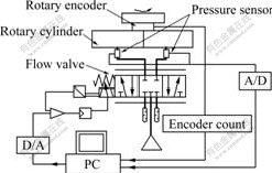
Fig.1 Configuration of pneumatic rotary position system
the rotary cylinder, which is the system-controlled object. Pressure sensors detect the pressure of the inlet and outlet of the rotary cylinder, which approximately equals the pressure of the two cylinder chambers. Using the electro-pneumatic flow proportional valve as a control component, we can adjust the flow of gas in the two chambers of actuator and change the chambers’ pressure. The pressure difference between the two cylinder chambers pushes the rack of the actuator to move, so the axis of the actuator can revolve to the required angle at last.
3 Mathematic models of system
3.1 Flow equation of system
Considering the complexity of gas flowing, in order to analyze and solve the problems easily, the following assumptions are made.
(1) The gas is ideal gas, which meets the ideal gas state equation.
(2) The process is isoentropic adiabatic process when the gas flows through the valve ports.
(3) The temperature variation in the rotary cylinder chambers can be ignored.
(4) The leakage is ignored.
The equation of mass flow continuity for compressible fluids can be written as
 (1)
(1)
with  , the mass flow continuity equation
for gas in the rotary cylinder cavities can be obtained as follows:
 (2)
(2)
where p is the pressure, T is the thermodynamic temperature, V is the volume of the chamber, Vi is the initial volume of the chamber, and y is the piston displacement.
When the gas flows through the proportional valve port, mass flow continuity equations can be established as:
 (3)
(3)
 (4)
(4)
where 


 , W is the port
width, xv is the valve spool displacement, Ts and ps are the thermodynamic temperature and the pressure of the air supply, and p0 is the atmospheric pressure, kc is adiabatic coefficient.
3.2 Cross section equation of valve
Because the bandwidth of the valve is much larger than that of the system, we can take the flow valve as a proportional component.
 (5)
(5)
where Uv is the voltage command signal, and KU is the gain of the valve opening area to the command voltage.
3.3 Dynamic equation of rotary cylinder

 (6)
(6)
where A is the piston effective area of the cylinder, m is the mass of piston, J is the gear moment of inertia, df is the gear pitch circle diameter, θ is the revolving angle of rotary cylinder, B is the coefficient of piston viscosity damping, Mf is the load torque, and Fc is the coulomb friction.
The relationship between revolving angle of rotary cylinder and piston displacement can written as
 (7)
(7)
From the mathematic model of the pneumatic rotary position servo system, we can see that there is serious nonlinearity in the system and the model parameters change with the working point of the system. In order to improve the system performance, a feed forward compensation pole-placement self-tuning control method is adopted as the system control strategy due to its simplicity and good robustness.
4 Design of system controller
The essence of pole-placement method is to determine feedback control law which can make the poles of the closed-loop transfer function in desired positions. The diagram of a pole-placement self-tuning control system is shown in Fig.2 [7-11].
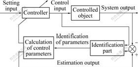
Fig.2 Diagram of pole-placement self-tuning system
4.1 Principle of feed forward compensation pole- placement self-tuning control
The controlled object can be described as the following mathematical model:
 (8)
(8)
where U(t) is the system control input, y(t) is the system output, and k is the delay factor.
 ,
,
 .
.
The desired closed-loop transfer function that satisfies the required performance is
 (9)
(9)
where  is the desired transfer function, and
 ,
,
 .
.
The objective of the control method is to find the control law u(t) that can make the system closed-loop transfer function equal to the desired transfer function. The control principle meeting the requirement is shown in Fig.3.
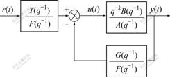
Fig.3 Diagram of feed forward compensation pole-placement self-tuning control system
The control law equation can be described as
 (10)
(10)
where r(t) is the desired system input and
 ,
,
 .
.
According to the control law u(t), the closed-loop transfer function of the system can be made equal to the desired transfer function.
Substituting Eqn.(10) into Eqn.(8), we obtain the closed-loop transfer function of the obtained system that is equal to the desired transfer function:
 (11)
(11)
The pole-zero of the closed-loop system will be the same as the desired transfer function according to the properly selecting F(q-1), G(q-1) and T(q-1) based on Eqn.(10).
If the system is non-minimum phase one, B(q-1) can be written as
 (12)
(12)
where B+(q-1) is the stable characteristic polynomial, and B-(q-1) is the unstable one. Because B(q-1) is the zero point of the open-loop system, the zero point that is not the one of the closed-loop system must be eliminated. As B(q-1) and A(q-1) are coprime, B+(q-1) must be one of the factors of F(q-1).
 (13)
(13)
As the unstable factors of the open-loop system cannot be eliminated, the desired transfer function zero point Bm(q-1) must include the unstable factor B-(q-1).
 (14)
(14)
and T(q-1) must include B′m(q-1). So
 (15)
(15)
Substituting Eqns.(12)-(14) into Eqn.(10), the identity, i.e., the characteristic polynomial of closed-loop of the controlled system can be obtained as follows:

(16)
 (17)
(17)
Under the condition of Eqn.(17), the control law can be calculated.
4.2 Design of feed forward compensation pole- placement self-tuning controller for system
The pneumatic rotary position servo system is an SISO system. Considering that the bandwidth of the pneumatic flow proportional valve is much larger than that of the system, the amplitude―frequency characteristics of the second order pneumatic position servo system at low frequency is similar with that of the third order one. The design of controller is easier if the model order of the system is lower. So the order of the controlled system is presumed as the second [12-15].
 (18)
(18)
where A(q-1) and B(q-1) are both the system characteristic polynomials; a1, a2, b1 and b2 are the system parameters that can be acquired by the on-line identification.
Define T0=1 and Am=1+p1q-1+ p2q-2
where p1 and p2 are parameters of the desired system characteristic polynomial.
If the system is non-minimum phase one and no process zero is eliminated, the following equations can be obtained:
Bm=aB=a(b+b1q-1) (19)
T=aT0=a (20)
As the pneumatic rotary position system is a servo system, the input is determined. Thus the gain of the transfer function of the desired closed-loop system at low
frequency is 1, that is to say,  . The following equations can be obtained:
 ,
,
 .
.
According to the condition for the unique solutions of Diophantine function:
 ,
,
 .
.
we can define G=g0+g1q-1 and F=f0.
Substituting the above into Eqn.(16), we obtain

 .
.
By solving the equations
 ,
,  , and
, and
 , the time series of the system control law can be described as
 (21)
(21)
4.3 parameters identification for controller
In the system identification, the performance of the identification arithmetic influences the accuracy of the discrete mathematical model directly and then affects the precision of the control system [16].
The least square method is one of the common parameter identification methods. General least square method may generate data saturation phenomenon with data increasing and lead to the decrease of the system control ability. But the least square method with fixed forgetting factors can make full use of the new data information and decrease the influence of old data so as to acquire the estimation of tracking parameters in real-time. The recursive least square method with fixed forgetting factors is used in the parameter estimation of the system controller in this work.
Substituting the observation vector φ and estimated parameter vector θ into the recursive least square formula with fixed forgetting factors, the control parameters can be estimated. The method can be described as follows:
θ(n+1)=θ(n)+K(n+1)[y(n+1)-φT(n+1)θ(n)] (22)
 (23)
(23)
P(n+1)=P(n)-K(n+1)KT(n+1)×[φT(n+1)P(n)φ(n+1)+ ] (24)
where y(n+1) is the rotation angle acquired by sample (n+1), ρ is the forgetting factor, K(n+1) is the gain matrix, and P(n) is the covariance matrix.
Using this identification method, the forgetting factor ρ is determined by the time-varying characteristics of parameters, the order of the system model and the disturbance type. In this system, let ρ=0.985. The observation vector and unknown parameter vector are, respectively, defined as follows:
φT(n)=[-y(n-1)-y(n-2)u(n-2)u(n-3)],
θ=[a1 a2 b1 b2]T.
5 Experiments
Based on the feed forward pole-placement self-tuning controller, the experimental research was carried out. The working flow chart of the control system is shown in Fig.4.
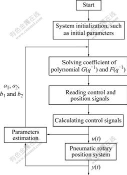
Fig.4 Flow chart of working of control system
When the controlled system tracks input signals, the system will be unstable if only PID control method is adopted. Because the pressure changes in the two rotary cylinder chambers are not synchronous and the friction of pneumatic cylinder piston is uncertain, all the factors above have great impacts on the system performance. But by applying the feed forward compensation pole-placement self-tuning method, the controlled pneumatic system can achieve good performance. This method has good on-line identification ability and can adjust the parameters adaptively. System responses under no load and 10 kg mass load to the square-wave signal (f=0.5 Hz, As=30?) are all good. The system steady state error is less than 1? and identified system parameters can be converged in 5 s. The experimental results are shown in Figs.5 and 6, showing that the number of shocks and energy consumption are both larger in the initial stage of the system than those in other stages. When the control parameters of identified system are converged and the system is stable, the system energy consumption is less than that at the beginning.
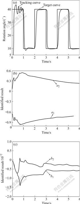
Fig.5 Responses of square-wave input without load: (a) System output and desired system input; (b) Identified system parameters a1 and a2; (c) Identified system parameters b1 and b2
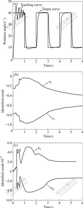
Fig.6 Responses of square-wave input under 10 kg mass load; (a) System output and desired system input; (b) Identified system parameters a1 and a2; (c) Identified system parameters b1 and b2
6 Conclusions
(1) Mathematical models for the pneumatic rotary position servo system with the electro-pneumatic flow proportional valve controlling rotary cylinder are built.
(2) The controller of feed forward compensation pole-placement self-tuning for the system is designed. As the controller has good ability to estimate the system parameters in real-time, it can improve the system performance and reduce the influence of factors that are not considered in the system models. Thus the controller system has good robustness of parametric anti- disturbance.
(3) Due to the influence by the controller system initial parameters, the controlled system output in the starting stage is not stable. But when the system is in the steady working state, the parameters of the adaptive control system tend to be convergent, and the output of the system tends to be stable. The identified method also has the advantages of fast convergence and high efficiency.
References
[1] BOBROW J E, MCDONELL B W. Modeling, identification, and control of pneumatically actuated robot [C]// Proceedings of the 1997 IEEE International Conference on Robotics and Automation. Piscataway: IEEE, 1997: 124-129.
[2] YANG Qing-jun, BAO Gang, NIE Bo-xun, WANG Zu-wen. Modeling of pneumatic cylinder controlled by electronic proportional directional valve [J]. Journal of Harbin Institute of Technology, 2001, 33(4): 495-498. (in Chinese)
[3] YANG Qing-jun, WANG Zu-wen, LU Jian-ping. Pneumatic servo system control via nonlinear H∞ control and direct feedback linearization [J]. Journal of Nanjing University of Science and Technology, 2002, 26(1): 52-56. (in Chinese)
[4] TANAKA K, SHIMIZU A, SAKATA K. Adaptive pole-placement control for pneumatic servo system with constant disturbances [J]. Trans on Society of Instrument and Control Engineers, 1994, 30(4): 1069-1076.
[5] FU Xiao-yun, LIU Hao, LI Bao-ren. Modeling and simulation of swing cylinder servo position system [J]. Machine Tool and Hydraulic, 2004, 33(8): 48-49. (in Chinese)
[6] BAI Yan-hong, LI Xiao-ning. Dual-loop control strategy with friction compensation for pneumatic rotary actuator position servo system [J].Journal of Nanjing University of Science and Technology, 2006, 30(2): 216-222. (in Chinese)
[7] FANG Chong-zhi, XIAO De-yun. Process identification [M]. Beijing: Tsinghua University Press, 1988. (in Chinese)
[8] WU Zhen-shun, JI Yong-tao, XU Wen-bo. Numeric zero-pole placement self-tuning adjuster dispersed with δ transposition and its application in hydraulic system [J]. Chinese Journal of Mechanical Engineering, 2002, 38(3): 127-130. (in Chinese)
[9] WU Shi-chang, WU Zhong-qiang. Adaptive control [M]. Beijing: China Machine Press, 2005. (in Chinese)
[10] WU Zhen-shun. Theory and application of adaptive control [M]. Harbin: Harbin Institute of Technology Press, 2005. (in Chinese)
[11] ZHANG You-wang, GUI Wei-hua. Compensation for secondary uncertainty in electro-hydraulic servo system by gain adaptive sliding mode variable structure control [J]. Journal of Central South University of Technology, 2008, 15(2): 256-263.
[12] REFAAT S, NAHAVANDI S. Nonlinear identification of pneumatic servo-drive [J]. International Journal of Modeling and Simulation, 2006, 26(1): 11-16.
[13] PENG Hui, WU Shao-cheng. Identification and control of typical industrial process [J]. Journal of Central South University of Technology, 2000, 7(3): 165-169.
[14] WANG Y T, CHANG M K. Comparative studies of simplified models of a two-axial pneumatic actuating system [J]. International Journal of Modeling and Simulation, 2000, 20(2): 130-135.
[15] BAI Yan-hong, LI Xiao-ning. Identification and modeling method for pneumatic position servo system [J]. Journal of Nanjing University of Science and Technology, 2007, 31(6): 710-714. (in Chinese)
[16] CHANG Che-hang, LIU Guan-jun. Hysteresis identification and compensation using a genetic algorithm with adaptive search space [J]. Mechatronics, 2007, 17(7): 391-402.
(Edited by CHEN Wei-ping)
Foundation item: Project(50375034) supported by the National Natural Science Foundation of China
Received date: 2008-12-18; Accepted date: 2009-03-12
Corresponding author: MAO Xin-tao, Doctoral candidate; Tel: +86-451-86413446-233; E-mail: maoxintao.hit@163.com

