Abstract: Hf films were synthesized by ion beam assisted deposition(IBAD). The influence of ion bombardment during deposition on the preferred orientation of films was studied. Hf film grains exhibit preferred (110) orientation when the growing film is bombarded by 500eV Ar+ ions at an incident angle of 75° and a current density of 0.9A/m2. When the current density is beyond 1.2A/m2, the Hf films exhibit mixed (002) and (100) orientation and which is not concerned with the ion incident angle. The reason for the preferred orientation of Hf film was discussed. It is considered that the preferred orientation of Hf films does not simply depend on the channeling effects of ions, or the grain surface energy, but it is the result of mutual competition and actions of several factors, which influences the crystallographic orientation of thin films in the non-equilibrium growth conditions.
Preferred crystal orientation of Hf films prepared by ion beam assisted depostion
Abstract:
Hf films were synthesized by ion beam assisted deposition(IBAD). The influence of ion bombardment during deposition on the preferred orientation of films was studied. Hf film grains exhibit preferred (110) orientation when the growing film is bombarded by 500 eV Ar+ions at an incident angle of 75° and a current density of 0.9 A/m2. When the current density is beyond 1.2 A/m2, the Hf films exhibit mixed (002) and (100) orientation and which is not concerned with the ion incident angle. The reason for the preferred orientation of Hf film was discussed. It is considered that the preferred orientation of Hf films does not simply depend on the channeling effects of ions, or the grain surface energy, but it is the result of mutual competition and actions of several factors, which influences the crystallographic orientation of thin films in the non-equilibrium growth conditions.
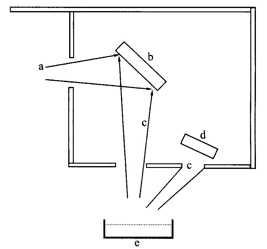
图1 高能离子束辅助沉积设备示意图 Fig.1 Schematic diagram of high energy ion beam assisted deposition system a―Xe+ ion beam; b―Sample; c―Hf vapor; d―Thickness monitor; e―Electron beam evaporator
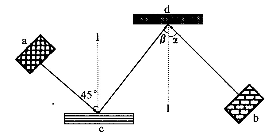
图2 低能离子束辅助沉积设备的工作示意图 Fig.2 Schematic diagram of low energy ion beam assisted deposition system a―Sputtering ion source; b―Bombardment ion source; c―Hf target; d―Sample; l―Normal line; α―Incidence angle of Ar+ ions; β―Incidence angle of sputted Hf atoms
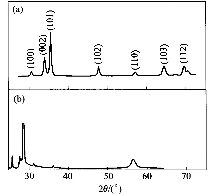
图3 纯金属铪材料和Ar+离子束 溅射方法沉积铪膜的X射线衍射谱 Fig.3 XRD patterns of pure Hf material and Hf films deposited on Si(111) substrates by sputtering method (a)― Pure Hf material; (b)―Hf films deposited by sputtering method
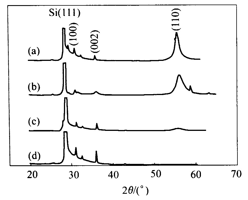
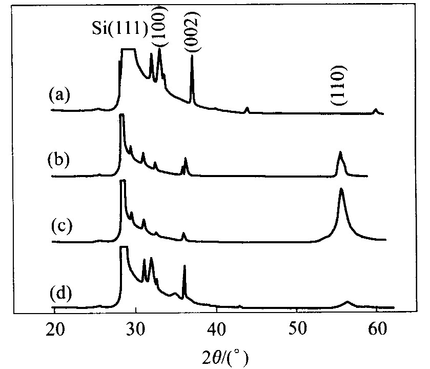
图4 Si(111) 衬底上不同Ar+离子入射角时低能离子束 辅助沉积铪膜的X射线衍射谱 Fig.4 XRD patterns of low energy IBAD Hf films deposited on Si (111) substrates with 500 eV Ar+ ions,0.9 A/m2 current density and different incidence angles (a)―75°; (b)―60°; (c)―45°; (d)―0°
图5 不同束流密度时低能离子束辅助沉积 铪膜的X射线衍射谱 Fig.5 XRD patterns of low energy IBAD Hf films deposited on Si (111) substrates with 500 eV Ar+ ions, 75° incidence angles and different current densities (a)―1.8 A/m2; (b)―1.2 A/m2; (c)―0.9 A/m2; (d)―0.6 A/m2
图6 不同电流密度时低能离子束 辅助沉积铪膜的X射线衍射谱 Fig.6 XRD patterns of low energy IBAD Hf films deposited on Si (111) substrates with 500 eV Ar+ ions, 0° incidence angles and different current densities (a)―0.9 A/m2; (b)―0.48 A/m2; (c)―0.36 A/m2; (d)―0.18 A/m2
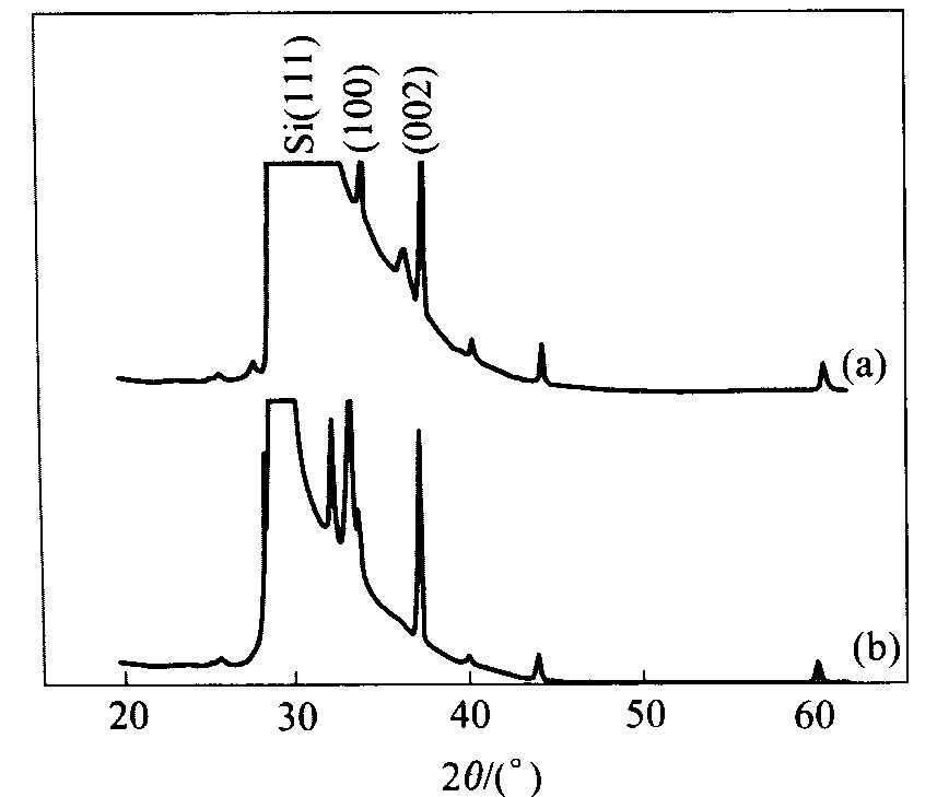
图7 高能(a)和低能(b)离子束 辅助沉积铪膜的X射线衍射谱 Fig.7 XRD patterns of Hf films on Si(111) substrate deposited by IBAD with high energy(a) and low energy(b)