
J. Cent. South Univ. (2020) 27: 3733-3743
DOI: https://doi.org/10.1007/s11771-020-4573-x

Research on improved active disturbance rejection control of continuous rotary motor electro-hydraulic servo system
WANG Xiao-jing(王晓晶), FENG Ya-ming(冯亚铭), SUN Yu-wei(孙宇微)
Key Laboratory of Advanced Manufacturing and Intelligent Technology (Ministry of Education),
Harbin University of Science and Technology, Harbin 150080, China
 Central South University Press and Springer-Verlag GmbH Germany, part of Springer Nature 2020
Abstract: In order to meet the precision requirements and tracking performance of the continuous rotary motor electro-hydraulic servo system under unknown strong non-linear and uncertain strong disturbance factors, such as dynamic uncertainty and parameter perturbation, an improved active disturbance rejection control (ADRC) strategy was proposed. The state space model of the fifth order closed-loop system was established based on the principle of valve-controlled hydraulic motor. Then the three parts of ADRC were improved by parameter perturbation and external disturbance; the fast tracking differentiator was introduced into linear and non-linear combinations; the nonlinear state error feedback was proposed using synovial control; the extended state observer was determined by nonlinear compensation. In addition, the grey wolf algorithm was used to set the parameters of the three parts. The simulation and experimental results show that the improved ADRC can realize the system frequency 12 Hz when the tracking accuracy and response speed meet the requirements of double ten indexes, which lay foundation for the motor application.
Key words: continuous rotary electro-hydraulic servo motor; active disturbance rejection control (ADRC); fast tracking differentiator (TD); non-linear state error feedback (NLSEF); extended state observer (ESO); grey wolf algorithm
Cite this article as: WANG Xiao-jing, FENG Ya-ming, SUN Yu-wei. Research on improved active disturbance rejection control of continuous rotary motor electro-hydraulic servo system [J]. Journal of Central South University, 2020, 27(12): 3733-3743. DOI: https://doi.org/10.1007/s11771-020-4573-x.
1 Introduction
As the core equipment of the simulation turntable for aerospace, continuous rotary electro-hydraulic servo motor has advantages of high frequency, high precision and super low speed [1, 2]. However, it is difficult for hydraulic motors to build accurate mathematical models, because the low-speed performance is affected by friction disturbance, internal and external leakage, noise interference and other non-linear uncertainties in the process of continuous rotation [3, 4]. It is necessary to design a controller to improve the control accuracy of continuous rotary motor electro- hydraulic servo system.
The active disturbance rejection control (ADRC) is improved on the basis of non-linear proportional-integral-derivative (PID) controller. It has absorbed the thought essence of classical PID control theory “based on the error to eliminate the error” [5-7], but also has overcome its unreasonable error method, integral feedback side effects and other shortcomings. A large number of numerical simulations [8, 9] and practical applications [10-12] have shown that the ADRC does not rely on the precise mathematical model of the controlled object, and can guarantee the control accuracy under the action of unknown strong non-linearity and uncertain strong disturbance. Both the internal uncertainty and the external disturbance of the model are considered a “total disturbance”, and the observer is used to estimate it in real time, then the disturbance is quickly eliminated because it is used in the feedback control. The ADRC has strong robustness and anti-interference, and less control quantity, so it is very suitable for engineering application [13, 14].
However, limited by the nonlinear and non-smooth feedback structure in ADRC, it is difficult to conduct theoretical analysis, and multiple parameters need to be adjusted and affect each other [15-17]. Some tuning methods [18-22] (linear programming algorithm, genetic algorithm, chaos particle swarm optimization algorithm, etc.) are used by researchers in ADRC, but they are only limited to low-order systems [23-25]. If the control of the high-order system of the electro-hydraulic servo motor is realized, the high-order ADRC is needed. At this point, the problem of the impact of the initial signal on the system exists, and the contradiction between overshoot and rapidity, the parameters of the extended state observer are too large and difficult to be set [26].
According to the problems of the above controllers, in order to ensure the control accuracy of continuous rotary motor electro-hydraulic servo system under the action of unknown nonlinearity and uncertainty disturbance, and to meet the low-speed performance of the motor, an improved ADRC strategy is designed in this paper, the tracking differentiator, non-linear state error feedback and extended state observer are designed respectively. The parameters of the controller are adjusted by the gray wolf algorithm [27, 28]. The validity of the control method is proved by Simulink simulation and experiment.
2 Establishment of continuous rotary electro-hydraulic servo motor model
The continuous rotary motor electro-hydraulic servo system is established according to the principle of valve-controlled hydraulic motor [29, 30]. The linearized flow equation of electro- hydraulic servo valve port is obtained by Laplace transform:
 (1)
(1)
where QL is the load flow, m3/s; Kq is the flow gain, m2/s; Xv is the spool displacement, m; Kc is the flow pressure coefficient, m3/(s・Pa); PL is the external load pressure, Pa.
Formula of the motor total load flow after Laplace transformation is expressed as below:
 (2)
(2)
where Dm is the radian displacement, m3/rad; θ is the angular displacement, rad; Ctm is the total leakage coefficient, m3/(s・Pa); Vt is the total volume of connecting pipe, motor and electro-hydraulic servo valve chamber, m3; βe is the effective bulk modulus of elasticity, Pa.
Moment balance equation of motor and load after Laplace transformation is expressed as below:
 (3)
(3)
where Jt is the total moment of inertia after the motor and external load are converted, kg・m2; Bm is the viscous damping coefficient, N・m/(rad/s); G is the spring stiffness of the load, N・m/rad; and TL is the external load torque acting on the motor, N・m.
According to Eqs. (1)-(3), the transfer function of the continuous rotary electro-hydraulic servo motor can be obtained. Assuming that the external load is rigidly connected with the motor, the simplified transfer function of the motor can be obtained and is expressed as follows:
 (4)
(4)
where Kce is the total flow-pressure coefficient of the valve-controlled motor, m3/(s・Pa), Kce=Kc+Ctm;  is the undamped hydraulic natural frequency, rad/s; and
  is the hydraulic damping ratio.
Because the natural frequency of the electro- hydraulic servo valve is higher than that of the hydraulic system, the transfer function of the electro-hydraulic servo valve is simplified to a second order oscillation link [31, 32]:
 (5)
(5)
As the frequency band of servo amplifier was significantly higher than the hydraulic natural frequency, its dynamic influences on the system can be ignored when designing the continuous rotary electro-hydraulic servo system. So, the servo amplification step can be simplified as a proportional link:
 (6)
(6)
where Ka is the servo amplifier gain, A/V.
The block diagram of the system for the continuous rotary motor electro-hydraulic servo system is established, as shown in Figure 1.
In Figure 1, θi(s) is the given input motor angle; θ(s) is the systematic output motor angle; K1 is the transfer function of the main controller of the electro-hydraulic servo system; and TL(s) is the applied load torque.
The open-loop transfer function of the system is established according to the block diagram:


 (7)
(7)
where K is the open-loop gain of the system, 
The state space model has good mathematical mapping ability and can solve the problems of high order systems and multivariate variables. The continuous rotary motor electro-hydraulic servo system is a fifth order system, and the state space expression of the closed-loop system is established in this paper.
 (8)
(8)
where


 D=0,
D=0, 


3 Design of improved ADRC
The three components of ADRC are improved respectively: the fast tracking differentiator (TD) with linear and non-linear combination is introduced to accelerate the transition process of the input signal; the non-linear state error feedback (NLESF) with synovial control is proposed to improve the rapidity and robustness of system response; the extended state observer (ESO) with non-linear compensation is proposed to solve the problems of phase lag caused by disturbance. The improved ADRC schematic diagram is shown in Figure 2.
In Figure 2, v1, v2, v3, v4, v5 are differential signals; u1, u2, u3, u4, u5 are control laws; z1, z2, z3, z4, z5, z6 are state variables. Refer to the following for detailed design.
3.1 Design of tracking differentiator
The fast tracking differentiator combining linear function and non-linear function is designed, which can not only improve the fast convergence of the tracking differentiator, but also avoid the flutter phenomenon caused by system instability [33, 34]. The fast tracking differentiator is designed to switch between linear and non-linear regions automatically, which ensures that the system can rapidly converge near and far from the equilibrium point.
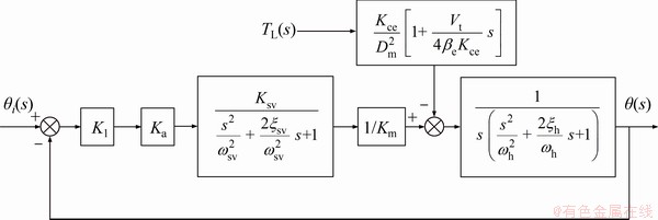
Figure 1 Block diagram of continuous rotary motor electro-hydraulic servo system
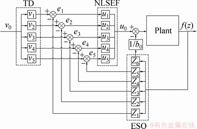
Figure 2 Structure diagram of improved ADRC
Take a second order system as follows:
 (9)
(9)
where a1>0, a2>0, b≥1; p and q are odd, and p>q>0.
The Lyapunov function is used to prove the stability of the tracking differentiator system proposed by Eq. (9).
 (10)
(10)
Take the derivative of Eq. (10), and then substitute in Eq. (9) to get Eq. (11).

 (11)
(11)
The stability of the system can be proved by Eq. (11). If meanwhile p>q, the nonlinear link plays a major role, and Eq. (10) can be simplified as follows:
 (12)
(12)
when  and
and  and p>q, the linear element plays a major role, and Eq. (10) can be simplified as follows:
 (13)
(13)
For the continuous rotary motor electro- hydraulic servo system, the formula of the fifth- order tracking differentiator with linear part and non-linear part can be designed as follows:
 (14)
(14)
where v0 is the system input angle signal; v1, v2, v3, v4, v5 are the differential speed signals of each order; a1, a2, b1, R are the parameter waiting for setting.
3.2 Design of non-linear state error feedback
The control law is introduced into the fast terminal sliding surface, which can avoid the influence of singular problems on the convergence rate of the system [35]. A fast terminal sliding surface is proposed as follows:
 (15)
(15)
where α>0, β>1 and 1<σ<2. The system state variable x1 and its first derivative x2 are considered here.
The difference between the system differential tracking signal and the extended state observation result is taken as the state variable.
 (16)
(16)
The derivative formula of terminal sliding surface with respect to error e is designed as follows:
 (17)
(17)
In order to shorten the approach time and ensure the low speed when the system reaches the sliding mode switching surface, the exponential approach law is selected as follows:
 (18)
(18)
where k1>0 and k2>0.
Combined with Eq. (15)-(18), the control law is obtained as follows:

 (19)
(19)
where k1, k2, α, β, b are variables.
The fifth-order nonlinear state error feedback is further derived as follows:
 (20)
(20)
where k1, k2, α, σβ, b2 are the parameters to be set.
3.3 Design of extended state observer
For the continuous rotating motor electro- hydraulic servo system, the non-linear uncertain objects with unknown interference are constructed as follows:
 (21)
(21)
where f(・)+w(t) is the non-linear function of the state variable and unknown interference; u(t) is the control amount; x(t) is the system state variables; x(t), x(1)(t), x(2)(t), x(3)(t), x(4)(t), x(5)(t) are the expanded state variable; and z1, z2, z3, z4, z5, z6 are the tracking amounts of the expanded state variables.
Since the disturbance of the system is unknown, the performance of the state variable of the system running process can be estimated. Therefore, the non-linear functions of state variables and unknown disturbances are replaced by dynamic compensation linearization:
 (22)
(22)
The non-linear system is established without considering the expanded state variable f(x, x(1), x(2), x(3), x(4), t) and w(t):
 (23)
(23)
where f(z1-x(t)), f(z2-x(1)(t)), f(z3-x(2)(t)), f(z4-x(3)(t)), f(z5-x(4)(t)), f(z6-x(5)(t)) are non-linear functions of independent variables z1-x(t), z2-x(1)(t), z3-x(2)(t), z4-x(3)(t), z5-x(4)(t), z6-x(5)(t), respectively.
Suppose:

 (24)
(24)
Then:
 (25)
(25)
The selection of nonlinear functions requires the following three conditions:
1) The non-linear function f is continuously differentiable.
2) f (0)=0.
3) The derivative is not equal to 0, namely, 
In order to solve this problem and reduce chattering, the hyperbolic tangent function is taken as the non-linear function:
 (26)
(26)
where e is constant.
The improved smooth extended state observer is presented as follows:
 (27)
(27)
Assume: δx1=z1-x1(t), δx2=z2-x2(t), δx3=z3- x3(t), δx4=z4-x4(t), δx5=z5-x5(t) and δx6=z6-x6(t).
The non-linear system can be obtained as follows:
 (28)
(28)
It is assumed that (i=1, 2, 3, 4, 5, 6) is dynamic compensation.
The state space equation of the system is expressed as follows:
 (29)
(29)
where which is the compensation matrix.
The selection of parameters l1, l2, l3, l4, l5, l6 is transformed into the selection of parameters η1, η2, η3, η4, η5, η6. Therefore, the nonlinear extended state observer with dynamic compensation can be obtained as follows:
 (30)
(30)
where η1, η2, η3, η4, η5, η6 are the parameters to be set.
4 Grey wolf optimization algorithms
Because the three parts of active disturbance rejection control (ADRC) work independently, the parameters of the three parts can be adjusted separately [36, 37]. The adaptability of traditional swarm intelligence algorithm to solve multi- objective optimization problem is not strong, so the gray wolf algorithm is used to solve high- dimensional and multi-objective optimization problems, due to its better flexibility, robustness and strong search ability.
The grey wolf algorithm is a new swarm intelligence optimization algorithm proposed by MIRJALILI et al in 2014 [38]. It is an iterative optimization algorithm by simulating the way of wolves management and predation. Compared with traditional particle swarm optimization and other artificial intelligence algorithms, the gray wolf algorithm has faster convergence speed and higher solution accuracy [39, 40].
The hunting process of gray wolf colony is simulated by the gray wolf algorithm, including two processes of surrounding prey and attacking prey.
1) Surround the prey
The distance between the wolves and their prey is shown as follows:
 (31)
(31)
 (32)
(32)
where X is the position vector of the wolf; Xp is the position vector of the prey; t is the current iteration step; and A, C are the coefficient vector, given by the following formula:
 (33)
(33)
where 
In order to avoid the parameter falling into the local optimal problem, the grey wolf algorithm is improved from the convergence factor. The value range of convergence factor a is known to be 0≤a≤2, and the value is obtained by linear decreasing method with the number of iterations. To improve the convergence speed of the optimization algorithm in the early stage and the optimization precision in the late stage, the non-linear function is selected to update the value of a.
 (34)
(34)
2) Attack the prey
Gray wolves gradually move closer to attack prey through individual position updates, and the formula for determining the distance between prey and α, β, δ is expressed as below:
 (35)
(35)
Then, update the position of α, β, δ:
 (36)
(36)
The position of the progeny wolves is obtained by Eq. (35):
 (37)
(37)
The objective function selection 
 is used to judge individual fitness of the gray wolf.
Specific steps of the grey wolf algorithm are as follows:
1) Initialize the population size N. Given the total number of iterations tmax, the initial value of the convergence factor 2, r1 and r2 are random, A and C are generated.
2) According to the objective function, the fitness values of all grey wolf individuals in the population were given and ranked; the first three good gray wolf positions Xα, Xβ, Xδ and the corresponding fitness values f (Xα), f (Xβ), f (Xδ) were selected.
3) Update a, A, C according to Eqs. (32) and (33).
4) Update the positions of other gray wolf instances according to Eq. (36), when the number of iterations is less than the total number of iterations.
5) The fitness of the other wolves is calculated and ranked, the positions and fitness values of the first three good gray wolves are selected as the Xα, Xβ, Xδ of the next optimization, and the number of iterations is increased by one.
6) The optimization is stopped and the best term Xα is output, when the number of iterations reaches the maximum number of iterations; otherwise, repeat steps 3 to 5.
The parameter setting results of ADRC are obtained as: a1=0.8466, a2=13.5694, b1=2.1510, R= 17.9157, k1=0.7671, k2=13.9781, α=5.0022, σβ= 8.5475, b2=8.5475, η1=0.8948, η2=10.5986, η3= 31.1455, η4=54.0129, η5=4.8654, η6=20.2919.
5 Study of simulation and experiment
5.1 Simulation
According to the Section 4, the controller parameter values based on gray wolf algorithm are obtained. Then, the controller is built in Simulink as Figure 3. The experimental results are compared with the simulation results to verify the rationality and effectiveness of the controller.
The simulation results show that when the slope of signal decreases, the response speed becomes slower and the tracking performance becomes worse. Figure 4 shows that under the condition of the error band formed by two straight lines of 0.0005°, using a slope input signal of 0.001°/s can make the controller basically meet the low-speed performance of the motor.
Good performance is required by simulator with the continuous rotary motor electro-hydraulic servo system, and the double-ten index as the specific quantitative scale means that amplitude error is less than 10%, and phase error is less than 10°. The responses of sinusoidal signal with the input amplitude of 1° and different frequencies are shown in Figure 5.
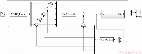
Figure 3 Simulation diagram of improved ADRC
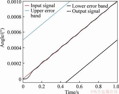
Figure 4 Slope response diagram of 0.001°/s
As shown in Table 1, with the increasing of sinusoidal signal frequency, the control effect will become worse. It still meets the requirement of double ten indexes at 12 Hz. It is proved that the improved ADRC is suitable for the continuous rotating motor electro-hydraulic servo system.
5.2 Experiment
The experiment platform was set up and C++ Builder software is used for the experiment. The simulation accuracy can be verified by the experiment. Experimental conditions are as follows: the oil temperature is 20-25 °C, the inertia of the load is 10 kg・m2, the oil source pressure is 10 MPa, and the outlet pressure of the reducing valve is 5 MPa.
The experimental images of slope signal and sinusoidal signal are obtained as follows.
The comparison results of sinusoidal experimental data and simulation data are shown in Table 2 and Figures 6 and 7.
The amplitude error and phase error values of the experimental results are both larger than the simulation results at the same frequency because of the existence of nonlinear factors such as leakage and friction interference, which has an impact on the tracking performance of the system. Both the experimental results and the simulation results can reach 12 Hz under the requirements of double ten indexes, which fully verify that the improved ADRC is suitable for the continuous rotating motor electro- hydraulic servo system.
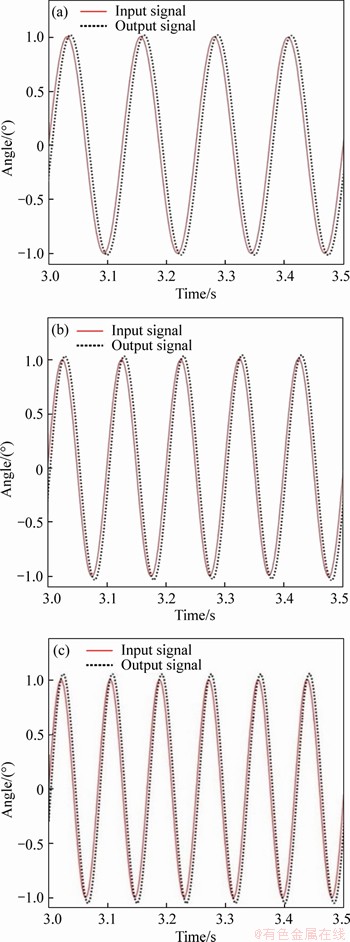
Figure 5 Sinusoidal response diagram of 8 Hz and 1° (a),10 Hz and 1° (b) and 12 Hz and 1° (c)
Table 1 Tracking performance of improved ADRC
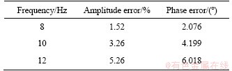
Table 2 Comparison results of sinusoidal response data
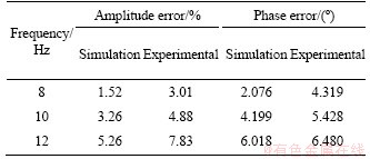
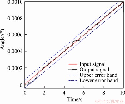
Figure 6 Experiment results of 0.001°/s
6 Conclusions
Based on the ADRC principle, the improved ADRC is designed for the continuous rotating motor electro-hydraulic servo system. The fast tracking differentiator is improved by combining linear and non-linear functions, which can improve the quick response of the system and speed up the transition process. The non-linear state error feedback is improved based on the terminal sliding mode surface, which can increase the stability of the experimental system and solve singular problems. The extended state observer is improved by means of compensation, which can reduce system tracking lag problems. The grey wolf algorithm is used to reduce the complexity of parameter setting of ADRC. According to the simulation and experiment, the system frequency of the controller is increased to 12 Hz when the tracking accuracy and response speed both meet the requirements of double ten, it is proved that the controller is suitable for precise control of electro-hydraulic position servo system.
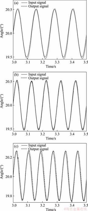
Figure 7 Experiment results of 8 Hz and 0.5°(a), 10 Hz and 0.5°(b) and 12 Hz and 0.25°(c)
Contributors
The overarching research goals were developed by WANG Xiao-jing, FENG Ya-ming, and SUN Yu-wei. WANG Xiao-jing established the mathematical model of the valve controlled motor, compiled the experimental program, calculated and analyzed the measured data. FENG Ya-ming and SUN Yu-wei designed the improved ADRC and adjusted the parameters to get the simulation curve. The initial draft of the manuscript was written by WANG Xiao-jing, FENG Ya-ming and SUN Yu-wei. All authors replied to reviewers’ comments and revised the final version.
Conflict of interest
WANG Xiao-jing, FENG Ya-ming and SUN Yu-wei declare that they have no conflict of interest.
References
[1] WANG Xiao-jing, LIU Mei-zhen, CHEN Shuai, LI Song. Predictive function and sliding model controller of continuous rotary electro-hydraulic servo motor applied to simulator [J]. Journal of Jilin University (Engineering and Technology Edition), 2019, 49(5): 1547-1557. DOI: 10.13229/j.cnki. jdxbgxb20180507. (in Chinese)
[2] YUAN Li-peng, CUI Shu-mei, LU Hong-ying, LI Shang-yi. Research on low speed performance of electro-hydraulic servomotor based on improved simulated annealing genetic algorithm [J]. Journal of Shanghai Jiao Tong University, 2010, 44(12): 1741-1746. DOI: 10.16183/j.cnki.jsjtu.2010. 12.022. (in Chinese)
[3] CAO Jian, MA Yu-hua, WU Xiao-feng. Application of QFT in continuous rotary electro-hydraulic servo motor [J]. Journal of Harbin Institute of Technology, 2009, 41(11): 69-72, 128. DOI: CNKI:SUN:HEBX.0.2009-11-014. (in Chinese)
[4] YUAN Li-peng. Structure optimization for improving low speed performance of continuous rotary electro-hydraulic servomotor based on the improved genetic algorithm [J]. Journal of Mechanical Engineering, 2010, 46(12): 166-174. DOI: CNKI:SUN:JXXB.0.2010-12-029.
[5] LI Min-zhao. Simulation Analysis of Disturbance suppression by ADRC [J]. Scientific and Technological Innovation, 2019(23): 47-48.
[6] LI Min-zhao. Simulation analysis of active disturbance rejection control technology based on simulink [J]. China Computer & Communication, 2019(1): 167-168, 171. DOI: CNKI:SUN:XXDL.0.2019-01-075. (in Chinese)
[7] ZHAO Zhi-liang. Active disturbance rejection control technology and theoretical analysis [M]. Beijing: Science Press, 2019.
[8] MA Zhuang, LIU Peng, WANG Jian-long. Simulation study on classical RLC system based on active disturbance rejection control [J]. Journal of Tangshan University, 2019, 32(6): 5-8, 42. DOI: 10.16160/j.cnki.tsxyxb.2019.06.002. (in Chinese)
[9] TIAN Gang, GAO Zhi-qiang. Frequency response analysis of active disturbance rejection based control system [C]// Proceedings of the 16th IEEE International Conference on Control, Applications Part of IEEE Multi-conference on Systems and Control. Singapore: IEEE, 2007: 1595-1599. DOI: 10.1109/CCA.2007.4389465.
[10] XIA Yuan-qing, FU Meng-yin, DENG Zhi-hong, REN Xue- mei. Recent developments in sliding mode control and active disturbance rejection control [J]. Control Theory & Applications, 2013, 30(2): 137-147. DOI: 10.7641/CTA. 2013.20498. (in Chinese)
[11] SHEN Wei, CUI Xia. Study on hydraulic motor speed servo system controlled by proportional servo valves with active disturbance rejection controller [J]. Computer Simulation, 2016, 33(8): 317-321. DOI: 10.3969/j.issn.1006-9348.2016. 08.069. (in Chinese)
[12] MA Shun-jian, SUN Ming-wei, CHEN Zeng-qiang. Interactive ADRC design for flight attitude control [C]// Proceedings of 2017 IEEE 6th Data Driven Control and Learning Systems Conference(DDCLS’17). IEEE Beijing Section. Beijing: IEEE Industrial Electronics Society, 2017. DOI: 10.1109/ddcls.2017.8068142.
[13] ZHANG Xi-dan, YIN Da-yi. Simulation study of active disturbance rejection controller for high order systems [J]. Aerospace Control, 2018, 36(1): 3-7, 13. DOI: 10.16804/ j.cnki. issn1006-3242.2018.01.001. (in Chinese)
[14] CHEN Zeng-qiang, LIU Jun-jie, SUN Ming-wei. Overview of a novel control method: active disturbance rejection control technology and its practical applications [J]. CAAI Transactions on Intelligent Systems, 2018, 13(6): 865-877. DOI: 10.11992/tis. 201711029. (in Chinese)
[15] FU Cai-fen, TAN Wen. Parameters tuning of linear active disturbance rejection control based on high order controller design [J]. Control Theory & Applications, 2017, 34(2): 265-272. DOI: 10.7641/CTA.2017.60039. (in Chinese)
[16] GUO Bao-zhu, ZHAO Zhi-liang. Active disturbance rejection control: Theoretical perspectives [J]. Communications in Information and Systems, 2015, 15(3): 361-421. DOI: 10.4310/CIS.2015.v15.n3.a3.
[17] ZHANG Hua, ZHENG Jia-qiang. Study on the design method of an active disturbance rejection optimal controller [J]. Control Engineering, 2018, 25(12): 2219-2223. DOI: 10.14107/j.cnki.kzgc.161003.
[18] ZHANG Meng, YU Jian, PANG Qing-wen, ZHAO Mo-lin. Research on auto disturbance rejection parameter tuning based on multi target moth optimization algorithm [J]. Microelectronics & Computer, 2018, 35(11): 84-88. DOI: CNKI:SUN:WXYJ.0.2018-11-017. (in Chinese)
[19] LIU Chun-fang, ZANG Bin. Application and the parameter tuning of ADRC based on CPSO [C]// Proceedings of the 24th Chinese Control and Decision Conference. Taiyuan: IEEE, 2012: 3277-3281. DOI: 10.1109/CCDC.2012.6243 084.
[20] HU Yi, WANG Min-gang, YANG Yao. Parameters tuning of active disturbance rejection controller (ADRC) based on artificial fish swarm algorithm (AFSA) [J]. Command Control & Simulation, 2013, 35(2): 90-92, 107. (in Chinese)
[21] LI Jia-hao, SUN Hong-fei. Improvement and application of active disturbance rejection control [J]. Journal of Xiamen University (Natural Science Edition), 2018, 57(5): 695-701. DOI: CNKI:SUN:XDZK.0.2018-05-017. (in Chinese)
[22] SUN Yu-meng, ZHANG Xu-xiu. Parameter setting and application of ADRC by improved genetic algorithm [J]. Automation and Instrumentation, 2020, 35(3): 13-17, 45. DOI: 10.19557/j.cnki.1001-9944.2020.03.004.
[23] HAN Wen-jie, TAN Wen. Parameter tuning of linear ADRC based on PID parameter tuning [EB/OL]. [2020-06-16]. https://doi.org/10.13195/j.kzyjc.2019.1408.
[24] ZHOU Tao. Parameter optimization of linear ADRC based on differential evolution algorithm [EB/OL]. [2020-06-16]. http://kns.cnki.net/kcms/detail/41.1228.TJ.20200219.0959.002.html.
[25] BAI Jie, ZHU Ri-xing, WANG Wei, MA Zhen. Control method based on linear ADRC controller design [J]. Science, Technology and Engineering, 2020, 20(10): 4149-4153.
[26] GAO Yang, WU Wen-hai, GAO Li. Linear ADRC for high order uncertain nonlinear systems [J]. Control and Decision, 2020, 35(2): 483-491. DOI:10.13195/j.kzyjc.2018.0550.
[27] LIU Jun-feng, YANG Zhe, LI Ding-fang. A multiple search strategies based grey wolf optimizer for solving multi-objective optimization problems [J]. Expert Systems with Applications, 2020, 145: 113134. DOI: 10.1016/ j.eswa.2019.113134.
[28] RASHID T A, ABBAS D K, TUREL Y K. A multi hidden recurrent neural network with a modified grey wolf optimizer [J]. PloS One, 2019, 14(3). DOI: 10.1371/ journal.pone.0213237.
[29] ZHANG Hua, ZHENG Jia-qiang, XU You-lin. Study of auto disturbance rejection synchronous control for bilateral hydraulic motor of concept sprayer chassis [J]. Journal of China Agricultural University, 2017, 22(6): 135-143. DOI: 10.11841/j.issn.1007-4333.2017.06.16. (in Chinese)
[30] YANG Guo-lai, WANG Hao-ze, GUO Long, HUANG Su-dan, GONG Wen-na. Simulation research on dynamic characteristic control of hydraulic valve-controlled motor [J]. Hydraulics Pneumatics & Seals, 2017, 37(1): 27-30. DOI: 10.3969/j.issn.1008-0813.2017.01.006. (in Chinese)
[31] HE Han-lin. Research on frequency domain and time domain dynamic characteristics of servo valve [J]. Hydraulics Pneumatics & Seals, 2019, 39(11): 26-28, 32.
[32] SHENG Xi-zheng, ZHONG Xiao-qin, XU Yi, JI Qi-qiang. Design and simulation analysis of electro-hydraulic position servo system [J]. Laboratory Research and Exploration, 2019, 38(4): 85-89. DOI: CNKI:SUN:SYSY.0. 2019-04-022.
[33] YAO Zhi-ying, CAO Hai-qing. A novel tracking differentiator with good stability and rapidity and its application [J]. Transactions of Beijing Institute of Technology, 2018, 38(8): 861-867. DOI: CNKI:SUN:BJLG. 0.2018-08- 015. (in Chinese)
[34] LIU Zhi-gao. Design of improved tracking differentiator [J]. Navigation and Control, 2018, 17(4): 61-65. DOI: CNKI: SUN:DHKZ.0.2018-04-011.
[35] CHE Jian-feng. Research on control of four rotor UAV Based on sliding mode auto disturbance rejection technology [D]. Tianjin: Tianjin University of Technology, 2019. (in Chinese)
[36] CHEN De-min, GU Hong-yan, ZHANG Dong-dong, AN Yin-min. Active disturbance rejection control for steam temperature system of circulating fluidized bed boiler [J]. Journal of Guizhou University, 2019, 36(3): 91-95. DOI: 10.15958/j.cnki.gdxbzrb.2019.03.17. (in Chinese)
[37] ZHOU Zhi-gang. Application of active disturbance rejection control in superheated steam temperature and parameter optimization [D]. North China Electric Power University, 2019. (in Chinese)
[38] MIRJALILI S, MIRJALILI S M, LEWIS A. Grey wolf optimizer [J]. Advances in Engineering Software, 2014, 69: 46-61. DOI: 10.1016/j.advengsoft.2013.12.007.
[39] ESWARAMOORTHY S, SIVAKUMARAN N, SEKARAN S. Grey wolf optimization based parameter selection for support vector machines [J]. COMPEL-the International Journal for Computation and Mathematics in Electrical and Electronic Engineering, 2016, 35(5): 1513-1523. DOI: 10. 1108/COMPEL-09-2015-0337.
[40] JITKONGCHUEN D, PHAIDANG P, PONGTAWEVIRAT P, PIYALAK P. An adaptive elitism-based immigration for grey wolf optimization algorithm [C]// 2017 International Conference on Digital Arts, Media and Technology (ICDAMT). IEEE, 2017. DOI: 10.1109/ICDAMT.2017. 7904965.
(Edited by ZHENG Yu-tong)
中文导读
连续回转马达电液位置伺服系统的改进自抗扰控制
摘要:为满足连续回转电液伺服马达系统在动态不确定性、参数摄动等未知强非线性和不确定强扰动因素下的精度需求和跟踪性能,提出了一种改进自抗扰控制(ADRC)策略。在阀控液压马达原理的基础上,建立马达五阶闭环系统状态空间模型。利用参数摄动和外部扰动对自抗扰控制器三部分进行改进,引入线性与非线性组合的快速跟踪微分器,提出用滑膜控制改进非线性状态误差反馈控制律,确定非线性补偿的扩张状态观测器。利用灰狼算法分别对三个部分进行参数整定。结果表明,在跟踪精度和响应速度均满足双十指标要求下,改进自抗扰控制器能够使系统频率达到12 Hz,为马达的实际应用奠定了基础。
关键词:连续回转电液伺服马达;自抗扰控制;快速跟踪微分器;非线性状态误差反馈控制律;扩张状态观测器;灰狼算法
Foundation item: Project(51975164) supported by the National Natural Science Foundation of China; Project(2019-KYYWF-0205) supported by the Fundamental Research Foundation for Universities of Heilongjiang Province, China
Received date: 2020-02-06; Accepted date: 2020-06-14
Corresponding author: WANG Xiao-jing, PhD, Professor; Tel: +86-18903669159; E-mail: hitwangxiaojing@163.com; ORCID: https:// orcid.org/0000-0001-6285-9193

