
J. Cent. South Univ. (2020) 27: 621-628
DOI: https://doi.org/10.1007/s11771-020-4321-2

Crashworthiness of innovative hexagonal honeycomb-like structures subjected to out-of-plane compression
WANG Zhong-gang(���и�)1, 2, SHI Chong(ʩ��)2, DING San-san(������)1, LIANG Xi-feng(��ϰ��)2
1. CRRC Qingdao Sifang Co., Ltd., Qingdao 266111, China;
2. Key Laboratory of Traffic Safety on Track (Ministry of Education), School of Traffic and Transportation Engineering, Central South University, Changsha 410075, China
 Central South University Press and Springer-Verlag GmbH Germany, part of Springer Nature 2020
Abstract: Seeking for innovative structures with higher mechanical performance is a continuous target in railway vehicle crashworthiness design. In the present study, three types of hexagonal reinforced honeycomb-like structures were developed and analyzed subjected to out-of-plane compression, namely triangular honeycomb (TH), double honeycomb (DH) and full inside honeycomb (FH). Theoretical formulas of average force and specific energy absorption (SEA) were constructed based on the energy minimization principle. To validate, corresponding numerical simulations were carried out by explicit finite element method. Good agreement has been observed between them. The results show that all these honeycomb-like structures maintain the same collapsed stages as conventional honeycomb; cell reinforcement can significantly promote the performance, both in the average force and SEA; full inside honeycomb performs better than the general, triangular and double schemes in average force; meanwhile, its SEA is close to that of double scheme; toroidal surface can dissipate higher plastic energy, so more toroidal surfaces should be considered in design of thin-walled structure. These achievements pave a way for designing high-performance cellular energy absorption devices.
Key words: honeycomb-like structure; crashworthiness; basic fold element; structural reinforcement
Cite this article as: WANG Zhong-gang, SHI Chong, DING San-san, LIANG Xi-feng. Crashworthiness of innovative hexagonal honeycomb-like structures subjected to out-of-plane compression [J]. Journal of Central South University, 2020, 27(2): 621-628. DOI:https://doi.org/10.1007/s11771-020-4321-2.
1 Introduction
Train collision causes heavy casualties and huge economic losses. Exploiting train��s highly crashworthy devices is an effective way. Cellular honeycomb structure has been considered the main potential energy absorption material in engineering application circle [1-3], due to its excellent ratio in weight to cost and stable plateau stage, as shown in Figure 1(a). In recent years, besides kinds of lightweight structures [4-9], filled [10], embedded [11], tandem [12], hierarchical [13-15] and multi-cell patterns [16-18] were continually developed.
Although fruitful innovative structures were proposed, further investigation on this topic needs to be deeply conducted, particularly for its superiority in economy, simple as well as behavior stability. From the previous study [19-20], it has been confirmed that collapse mode of honeycomb cell mainly happens near foil wall when undergoing out-of-plane compression. After walls��folding, some considerable empty zone in the center of each cell can be observed clearly. Developing innovative honeycomb-like structure in reinforcing each cell could be as an effective way of sufficiently reusing the foil wall distribution, so as to increase the energy absorption capacities.
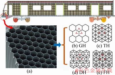
Figure 1 Honeycomb application (a) and novel structures (b-e)
In this study, three types of reinforced hexagonal honeycomb-like structures were theoretically and numerically analyzed subjected to out-of-plane compression, namely, triangular honeycomb, double honeycomb and full inside honeycomb, based on conventional general honeycomb. They are abbreviated as TH, DH, FH and GH, respectively, as shown in Figures 1(b) and (e) below.
2 Theoretical analyses
2.1 Geometric characterization
For any piece of honeycomb-like core block, it consists of lots of basic units. For instance, GH, it contains many ��Y�� sections (see Figure 2(a)). In each ��Y�� section, it can be described with the cell foil thickness t, cell edge length h, cell edge width l, and tilt angle ��. This study only discusses the case of h=l, ��=��/3. For DH and FH, the edge length of inside small hexagonal cell is exactly half of the original one. That means that the inside reinforced hexagons locate in the middle of original cell.
According to geometrical configuration, the weight Mc of the foil in red dashed triangular area (see Figure 1(b)) can be calculated as
 (1)
(1)
in which ��0is the density of foil material and T is the total height of specimen. Its volume Vc is
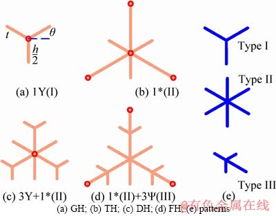
Figure 2 Scheme of basic unit:
 (2)
(2)
Hence, the relative density ��cg can be calculated as ��cg=Mc/Vcand is simplified as
 (3)
(3)
Following the same rule, the relative density ��ct, ��cd and ��cf respectively for TH, DH and FH can be expressed as
 (4)
(4)
 (5)
(5)
 (6)
(6)
Observing the basic units, there are three types of typical elements mentioned, including ��Y�� pattern (type I), ��*�� pattern (type II) and ������pattern (type III), as shown in Figure 2. Their lengths involved in each element are different from each other.
2.2 Theoretical formulas
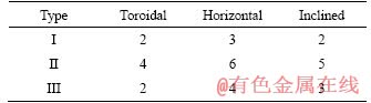
As widely known, for a basic unit, when undergoing out-of-plane compression, the dissipation region of localized energy contains the toroidal surface E1, horizontal hinge line E2, and inclined hinge line E3. In each fold, the plastic energy in 2H crush distance can be respectively calculated respectively as:
 (7)
(7)
 (8)
(8)
 (9)
(9)
where H is half-wave length; the unknown temporary parameter b is the small radius of the toroidal shell; c represents the wall length of each fold; M0 is the fully plastic bending moment calculated as M0=��0t2/4, in which ��0 stands for the yield strength of foil (in the case of idealized elastic-plastic material behavior); I1(f0)=1.05, I3(f0)=2.39 and f0=��/3. Generally, the energy dissipation can be regarded as the sum of the former three parts by calculating all localized regions listed in Table 1.
Table 1 Localized regions
Considering the full fold element subjected to out-of-plane static compression, energy dissipations can be calculated based on the energy minimal principle.
1) For the conventional honeycomb (GH), there is only ��Y�� pattern element (see Figure 2(a)), and its plastic internal energy Eg can be expressed by following equation and numbers listed in Table 1, as follows:

 (10)
(10)
while the external work Wext can be calculated as:
Wext=2PmgHg (11)
where Pmg is the average force in 2Hg folding distance. Therefore, according to the energy balance principle, the external work must be equal to the internal dissipation, i.e. Wext=Eg. Thus, the equation can be constructed as:
 (12)
(12)
The minimal energy principle tells that the least Pmg leads to collapse happening. Hence, Hg and bg can be determined by letting  Pmg/Hg=0, Pmg/bg=0. Consequently, Hg and Pmg can be obtained respectively as:
 (13)
(13)
 (14)
(14)
In this fold, the unit weight of foil walls is Mg=3��0htHg. Hence, the specific energy absorption smg in 2Hg distance can be obtained as follows:
 (15)
(15)
2) For TH, it can also be regarded as the sum of specific elements marked in Figure 2(b). This basic unit contains a ��*�� type element. In addition, the plastic energy Edp of the three marginal points should be added. Similarly, the total energy of the basic unit Et can be calculated as:
Et=E*+3Edp (16)
in which

 (17)
(17)

 (18)
(18)
where Ht is the half-wave length; bt is the unknown temporary parameter. Substituting Eqs. (17) and (18) into Eq. (16), Et can be re-written as:
 (19)
(19)
Thus, the equation can be built as
 (20)
(20)
Also letting Pmt/Ht=0, Pmt/bt=0, Ht and Pmt can be solved as:
 (21)
(21)
 (22)
(22)
For TH structure, its unit weight of foil walls is Mg=4.5��0htHt.Hence, the SEA smt can be expressed as:
 (23)
(23)
3) For DH, it can be divided into 3 type I elements and 1 type II element. They dissipate energy Eyand E*, respectively. The plastic energy absorption Ed in 2Hd can be calculated as:
Ed=E*+3Ey (24)
where

 (25)
(25)

 (26)
(26)
Likewise, bd is the unknown temporary parameter. Substituting Eq. (25) and (26) back into Eq. (24), then Ed can be re-written as:
 (27)
(27)
Likewise, the equation can be built as:
 (28)
(28)
In the same manner, the half wave-length and the mean crushing force can be expressed as follows:
 (29)
(29)
 (30)
(30)
As the same as the former derivation, its unit weight of foil walls is Md=4.5��0htHd. Hence, the specific energy absorption smd can be obtained as:
 (31)
(31)
4) For FH, this type of unit can be divided into 3 type III elements and 1 type II one. Besides the energy consumed by type III (E��) and type II (E*), as the former, the total dissipated energy Ef also contains the part consumed by three marginal points (Edq):
Ef=E*+3E��+3Edq (32)
in which

 (33)
(33)

 (34)
(34)
 (35)
(35)
where Hf is the half wave-length; bf is the temporary parameter. Hence, the total energy Ef can be summed by all parts in Eqs. (32)-(35) as:
 (36)
(36)
Thus, the equation of average force, Pmf, related to Hf and bf can be constructed as:
 (37)
(37)
Similarly, Pmf and Hf can be solved as:
 (38)
(38)
 (39)
(39)
and the specific energy absorption smf of this unit (Mf=6��0htHf) can be obtained:
 (40)
(40)
Table 2 summaries all the results obtained in the theoretical derivation for folding units presented in Figure 2.
3 Numerical simulations
3.1 Finite element model
For each numerical honeycomb specimen, the finite element model was built with commercial software package LS-DYNA [21]. Their cells were meshed with BT4 (Belytschko-Tsay-4node) shell elements and the mesh size was designed as 0.5 mm. Each model had 11 cells in L-direction and 11 cells in W-direction (see Figure 3), which completely satisfies the requirement of the minimum cell number (see Ref. [22]). For each cell, t=0.06 mm, h=l=4 mm. They were 40 mm in T-direction (see Figure 3). The foil material was AL 5052H18, and it was treated as an idealized elastic-plastic constitution model, with the mechanical properties: density 2680 kg/m3, elastic module 69.3 GPa, Poisson ratio 0.33, yield stress 215 MPa. Automatic single surface contact algorithm was applied to avoiding penetration between cell walls. The specimen was placed on a static rigid plate as a boundary and crushed by another moving rigid plate at a constant velocity 36 km/s, to meet the standard for railway vehicle crashworthiness design [23], as shown in Figure 3.
Table 2 Theoretical results
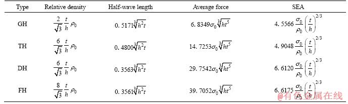
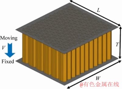
Figure 3 Loading situation
3.2 Validation
General honeycomb structure was employed representatively to validate the numerical finite element model, with the same t=0.06 mm, h=l=4 mm. Here, the top rigid plate moves at a constant speed 0.5 m/s. Corresponding compression history of nominal stress versus strain as well as theoretical derivation result (substituting corresponding parameters back into Eq. (14), the result is 1.0327 MPa) is given in Figure 4. Good agreement between them adequately validates the finite element model.
3.3 Results
Figure 5 shows the numerical results of the response force versus displacement of these four structures (GH, TH, DH and FH).
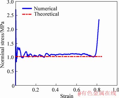
Figure 4 FEM model validation
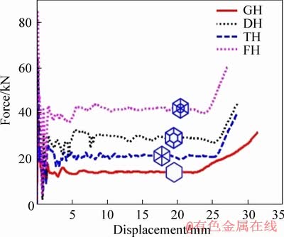
Figure 5 Resultant curves of different structures
From the curves shown in Figure 5, it can be clearly seen that, the reinforced honeycomb-like structures maintain the same four stages with conventional one, including elastic, initial collapsed, progressively folding and densification. Figure 6 gives the result of the average force in plateau stage and SEA. As the bar heights indicate that, compared with GH, significant increments have been achieved for TH, DH and FH. The average force increases from 14.14 kN of GH, to 21.11 kN of TH. 29.15 kN of DH and 42.05 kN of FH, respectively. Meanwhile, the SEA increases from 16.62 kJ/kg of GH, to 17.73 kJ/kg of TH, 24.56 kJ/kg of DH and 24.72 kJ/kg of FH, accordingly. These indicate evident increments through cell reinforcement.
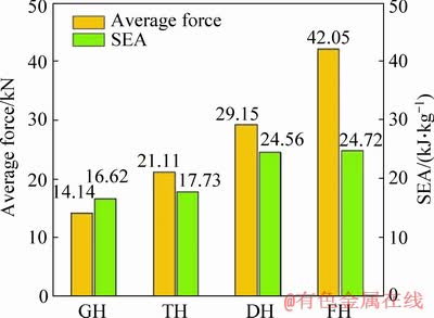
Figure 6 Increment of present structures
4 Discussion
4.1 Correlation analyses
SEA correlation was illustrated to validate the theoretical analyses. Differing from the theoretical equations derived under static situation, the numerical simulation was carried out under impact situation. Dynamic effect might influence the result. At the same time, the plastic energy dissipation is related to fold process, and heavily influenced by the folding ratio (usually be considered 0.73-0.75). Therefore, relative ratios are concentrated for these two cases. Figure 7 shows the SEA ration of TH, DH and FH compared with GH. The heights as well as values marks on the top of the bars sufficiently validate the outstanding agreement between theoretical derivation and numerical simulation.
4.2 Structural effect
From Table 2, it can be observed that, for these four types of structures, GH, TH, DH and FH, the average force and SEA have the same expression forms, but with different coefficients. The reasons for these mainly lie in their different half-wave lengths.
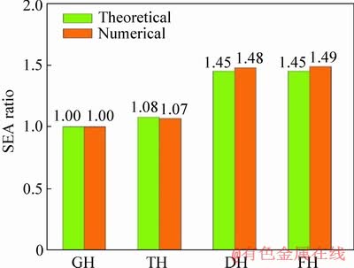
Figure 7 SEA ratio increments comparison
To illustrate these, Figure 8 shows the trends of half-wave length, the average force and SEA of the present structures. From figure, it can be seen that, FH has shorter half-wave length compared with GH, but performs the biggest average force and SEA. Both the DH and FH are stronger than GH and TH, because they have shorter half-wave lengths.
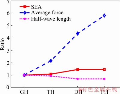
Figure 8 Influence of half-wave length on force and SEA
4.3 Formulas
For TH and DH, they have the same lengths of foil walls in each basic unit, also have the same relative densities. However, from Figures 5-8, it can be clearly found that the DH scheme is much better than TH, not only in average force, but also in SEA. This mainly owes to the folding localized energies from the toroidal surface and inclined hinge lines in each basic unit, because they have the same horizontal hinge lines.
From Eqs. (17)-(19) and Eqs. (24)-(27), Et and Ed can be re-written as:
 (41)
(41)
 (42)
(42)
Now that they have the same cell length of DH and TH, meeting
 (43)
(43)
It can be easily found that the coefficient of Ed in Eq. (42) is larger than that of Et in Eq. (41). This is the reason why Ed is much larger than Et. It indicates that toroidal surface can dissipate higher plastic energy. In design of lightweight energy absorption devices, more toroidal surfaces are recommended.
5 Conclusions
1) All these honeycomb-like structures maintain the same collapsed stages as conventional honeycomb structure. Based on these, they can be served as potential lightweight energy absorption devices.
2) Half-wave length of folding element heavily influences the mechanical performance. A honeycomb-like structure with shorter half-wave length has higher energy absorption capacity. Compared with general honeycomb, cell reinforcement can significantly promote the performance, not only in average force, but also in SEA. The reinforcement largely shortens half-wave length of the structure.
3) Compared with other structures, the half-wave length of FH is the shortest, but its average force and SEA are the biggest. DH and FH are both higher than GH and TH in load bearing ability. Considering the energy absorption capacity and lightweight, double reinforcement honeycomb scheme is recommended.
4) Toroidal surface can dissipate higher plastic energy. In design of lightweight energy absorption devices, more toroidal surfaces should be considered.
References
[1] WANG Z. Recent advances in novel metallic honeycomb structure [J]. Composites Part B, 2019, 166: 731-741.
[2] WANG Zhong-gang, WEI Zhou, LIU Jie-fu. Initial densification strain point��s determination of honeycomb structure subjected to out-of-plane compression [J]. Journal of Central South University, 2017, 24(7): 1671-1675.
[3] CUI C, WANG Z, ZHOU W, WU Y, WEI W. Branch point algorithm for structural irregularity determination of honeycomb [J]. Composites Part B, 2019, 162: 323-330.
[4] WANG Z, WANG X, SHI CHONG, ZHOU W. Mechanical behaviors of square metallic tube reinforced with rivets��Experiment and simulation [J]. International Journal of Mechanical Science, 2019, 163: 105118.
[5] JING L, SU X, CHEN D, YANG F, ZHAO L. Experimental and numerical study of sandwich beams with layered-gradient foam cores under low-velocity impact [J]. Thin-Walled Structures, 2019, 135: 227-244.
[6] XIAO Li-jun, SONG Wei-dong. Additively-manufactured functionally graded Ti-6Al-4V lattice structures with high strength under static and dynamic loading: Experiments [J]. International Journal of Impact Engineering, 2018, 111: 255-272.
[7] LI X, XIAO L, SONG W. Deformation and failure modes of Ti-6Al-4V lattice-walled tubes under uniaxial compression [J]. International Journal of Impact Engineering, 2019, 130: 27-40.
[8] XIAO L J, SONG W D, HU M L, LI P F. Compressive properties and micro-structural characteristics of Ti�C6Al�C4V fabricated by electron beam melting and selective laser melting [J]. Materials Science and Engineering A, 2019, 764: 138204.
[9] CHEN D, JING L, YANG F. Optimal design of sandwich panels with layered-gradient aluminum foam cores under air-blast loading [J]. Composites Part B, 2019, 166: 169-186.
[10] WANG Z, YAO S, LU Z, HUI D, FEO L. Matching effect of honeycomb-filled thin-walled square tube-experiment and simulation [J]. Composite Structures, 2016, 157: 494-505.
[11] LIU J, CHEN W S, HAO H, WANG Z. Numerical study of low-speed impact response of sandwich panel with tube filled honeycomb core [J]. Composite Structures, 2019, 220: 736-748.
[12] LI Meng, DENG Zong-quan, GUO Hong-wei, LIU Rong-qiang, DING Bei-chen. Optimizing crashworthiness design of square honeycomb structure [J]. Journal of Central South University, 2014, 21(3): 912-919.
[13] WANG Z, LI Z, SHI C, ZHOU W. Mechanical performance of vertex-based hierarchical vs square thin-walled multi-cell structure [J]. Thin-walled Struct, 2019, 134: 102-110.
[14] FANG J, SUN G, QIU N, PANG T, LI S, LI Q. On hierarchical honeycombs under out-of-plane crushing [J]. International Journal of Solids and Structures, 2018, 135: 1-13.
[15] WANG Z, LI Z, SHI CH, ZHOU W. Theoretical and numerical analysis of the folding mechanism of vertex-based hierarchical honeycomb structure [J]. Mechanics of Advanced Materials and Structures, 2019. DOI: 10.1080/ 15376494.2019.1665760.
[16] QIU N, GAO Y, FANG J, FENG Z, SUN G, LI Q. Crashworthiness analysis and design of multi-cell hexagonal columns under multiple loading cases [J]. Finite Elements in Analysis and Design, 2015, 104: 89-101.
[17] FANG J, GAO Y, SUN G, ZHENG G, LI Q. Dynamic crashing behavior of new extrudable multi-cell tubes with a functionally graded thickness [J]. International Journal of Mechanical Sciences, 2015, 103: 63-73.
[18] FANG J, GAO Y, SUN G, QIU N, LI Q. On design of multi-cell tubes under axial and oblique impact loads [J]. Thin-Walled Structures, 2015, 95: 115-126.
[19] WANG Z, LIU J. Numerical and theoretical analysis of honeycomb structure filled with circular aluminum tubes subjected to axial compression [J]. Composites Part B, 2019, 165: 626-635.
[20] WANG Z, LI Z, XIONG W. Numerical study on three-point bending behavior of honeycomb sandwich with ceramic tile [J]. Composites Part B, 2019, 167: 63-70.
[21] HALLQUIST J. LS-DYNA user��s manual[M]. Livemore Software Technology Corporation, 2003.
[22] WANG Z, LI Z, ZHOU W, HUI D. On the influence of structural defects for honeycomb structure [J]. Composites Part B, 2018, 142: 183-192.
[23] BS EN15227:2008. Railway applications��Crashworthiness requirements for railway vehicle bodies [S]. 2008.
(Edited by YANG Hua)
���ĵ���
������������ѽṹ������ѹ����������
ժҪ��̽Ѱ������ѧ���ܵ�������ӱ�ṹһֱ�ǹ��������ײ����Ƴ������Ŀ�ꡣΪ�ˣ�������������ǿ������ѽṹ������ѹ���������ԣ�����������ǿ�͡�˫����ǿ�ͺ�ȫ�����ǿ�͡�������С����ԭ�������˸�����ǿ���ѽṹ��ƽ�����������ܵ����۱���ʽ����������ʽ����Ԫ��ֵģ�ⷽ����֤������ǺϽϺá����ý������������������ѽṹά�����볣����ѽṹһ�µ�ѹ�����̣� ��Ԫ��ǿ��������������ѽṹ��ƽ̨�غ�������ܣ������������ǿ��ʽ��ȫ�����ǿ������ѽṹ��˫����ǿ�ͽṹ�����൱�ı����ܣ�����ƽ̨�غɸ��ߣ��۽ǵ�Ԫ��������ɺ�ɢ����������ܣ�Ӧ�������Ӹ����۽ǵ�Ԫ����������ˮƽ�����ý��Ϊ���ʶ��������������װ������ṩ�ο���
�ؼ��ʣ�����ѽṹ����ײ�ԣ������۵���Ԫ���ṹ��ǿ
Foundation item: Projects(51875581, 51505502) supported by the National Natural Science Foundation of China; Projects(2017M620358, 2018T110707) supported by China Postdoctoral Science Foundation; Project(kq1905057) supported by the Training Program for Excellent Young Innovators of Changsha, China
Received date: 2019-06-09; Accepted date: 2019-08-19
Corresponding author: SHI Chong, PhD Candidate; Tel: +86-731-82655294; E-mail: shichong@csu.edu.cn; ORCID: 0000-0001-9302- 3399

