Crashworthiness of double-cell conical tubes with different cross sections subjected to dynamic axial and oblique loads
��Դ�ڿ������ϴ�ѧѧ��(Ӣ�İ�)2018���3��
�������ߣ�PIRMOHAMMAD Sadjad Ekbatan Mohammad-Hossein Esmaeili-Marzdashti Sobhan
����ҳ�룺632 - 645
Key words��crashworthiness; dynamic axial and oblique load; double-cell conical tube; mean dynamic load
Abstract: Thin-walled tubes are increasingly used in automobile industries to improve structural safety. The present work deals with the collapse behavior of double-cell conical tubes subjected to dynamic axial and oblique loads. Crashworthiness of these tubes having different sections (e.g., circular, square, hexagonal, octagonal, decagonal) was numerically investigated by using an experimentally validated finite element model generated in LS-DYNA. Geometry of these tubes was then optimized by decreasing the cross section dimensions at the distal end while the weight remained unchanged. Octagonal conical tube was finally found to be more preferable to the others as a collision energy absorber. In addition, square and circular tubes showed diamond deformation mode, while the other tubes collapsed in concertina mode. A decision making method called TOPSIS was finally implemented on the numerical results to select the most efficient energy absorber.
Cite this article as: Pirmohammad Sadjad, Ekbatan Mohammad-Hossein, Esmaeili-Marzdashti Sobhan. Crashworthiness of double-cell conical tubes with different cross sections subjected to dynamic axial and oblique loads [J]. Journal of Central South University, 2018, 25(3): 632�C645. DOI: https://doi.org/10.1007/s11771-018-3766-z.

J. Cent. South Univ. (2018) 25: 632-645
DOI: https://doi.org/10.1007/s11771-018-3766-z

Pirmohammad Sadjad1, Ekbatan Mohammad-Hossein2, Esmaeili-Marzdashti Sobhan1
1. Department of Mechanical Engineering, University of Mohaghegh Ardabili, Ardabil 179, Iran;
2. Department of Mechanical Engineering, Azad University of Arak, Arak, Iran
 Central South University Press and Springer-Verlag GmbH Germany, part of Springer Nature 2018
Abstract: Thin-walled tubes are increasingly used in automobile industries to improve structural safety. The present work deals with the collapse behavior of double-cell conical tubes subjected to dynamic axial and oblique loads. Crashworthiness of these tubes having different sections (e.g., circular, square, hexagonal, octagonal, decagonal) was numerically investigated by using an experimentally validated finite element model generated in LS-DYNA. Geometry of these tubes was then optimized by decreasing the cross section dimensions at the distal end while the weight remained unchanged. Octagonal conical tube was finally found to be more preferable to the others as a collision energy absorber. In addition, square and circular tubes showed diamond deformation mode, while the other tubes collapsed in concertina mode. A decision making method called TOPSIS was finally implemented on the numerical results to select the most efficient energy absorber.
Key words: crashworthiness; dynamic axial and oblique load; double-cell conical tube; mean dynamic load
Cite this article as: Pirmohammad Sadjad, Ekbatan Mohammad-Hossein, Esmaeili-Marzdashti Sobhan. Crashworthiness of double-cell conical tubes with different cross sections subjected to dynamic axial and oblique loads [J]. Journal of Central South University, 2018, 25(3): 632�C645. DOI: https://doi.org/10.1007/s11771-018-3766-z.
1 Introduction
Simultaneous increase of the number and speed of automobiles in recent years led to higher demands for improving the crashworthiness capability of the automobiles to decrease the injuries in crash occurrences. Thus, there has been a growing interest in utilizing the high capacity energy absorbers. Several methods have been proposed in the past years to improve energy absorption capacity of these columns. Expanding metal tubes by rigid tubes [1], foam filled tubes [2], externally reinforcing by composite materials [3] and progressive folding formations [4�C7] are rarely mentioned. However, the last case is known to be the best method for absorbing the collision energy [8].
Weight is considered as a critical factor in automobile design and must be minimized. Saving in weight using lightweight materials such as aluminum can lead to reduction in fuel consumption and environmental pollution. Aluminum alloys stand out as attractive material for body constriction being about one third lighter than steel but possessing comparable strength. Aluminum also has superior corrosion resistance and recyclability when comparing to mild or high strength steels. Usage of aluminum would, however, undoubtedly have a negative impact on cost; although it may be possible to meet the cost objectives by using extruded members, optimizing design by using computer-aided engineering, and minimizing expenses related to manufacturing. From the lightening and crashworthiness point of view, an aluminum space frame is regarded as a very promising type of car body structure [9]. Another advantage of the structure made of aluminum is that any arbitrary cross-section can be manufactured by the extrusion process.
In addition to the use of aluminum materials to minimize the weight, a tube with better design in terms of the crashworthiness capability is the popular choice for the researchers. Energy absorption efficiency of a thin-walled column depends on numerous factors like material property, cross-section configuration and thickness. Many researches have focused on cross-section configurations for example circular [10�C12] and polygonal (i.e., square, rectangle, etc) tubes [13�C15]. Moreover, thin-walled columns with multiple cells have demonstrated desirable energy absorption efficiency [16, 17]. For example, numerical simulations performed by ZHANG et al [18] showed that the energy absorption efficiency of multi-cell columns was higher than that of foam- filled ones. Among the mentioned factors, the cross- section configuration is one of the most important issues.
Tapered thin-walled tubes are relatively new energy absorber. These structures are considered more preferable to straight tubes. In other words, the tapered tubes appear more advantageous as energy absorbers against axial and oblique impacts. For example, HOSSEINI-TEHRANI et al [19] showed that the tapered tubes with square cross-section dissipated more collision energy than straight tubes while both had the same weight. Compared with the traditional straight tubes, relatively few studies have been reported in the literature to optimize the tapered tubes in terms of energy absorption capacity. Some experimental works have been done to compare the load- deformation and collapse mode responses of none- tapered and tapered circular tubes subjected to axial quasi-static crushing [20�C23]. Recent investigations on these tubes have focused on different axial deformation modes [24�C26]. NAGEL et al [27�C29] compared the energy absorption capability of straight and tapered rectangular tubes under quasi- static and dynamic impact loading. They showed the advantages of using tapered tubes for energy absorption under oblique impact loading.
In this work, crashworthiness performance of conical tubes with various cross section shapes including square, hexagonal, octagonal, decagonal and circular were investigated numerically. A large number of numerical simulations, using explicit finite element code LS-DYNA, were made to find the best cross-section configuration possessing the highest energy absorption capacity. Moreover, dimensions of the conical tubes were optimized in order to achieve the minimum weight without compromising crashworthiness capacity of the conical tubes.
2 Problem descriptions
Based on an investigation performed by HOSSIENI-TEHRANI et al [30], straight tubes absorb more collision energy than S-shaped tubes. Consequently, a straight tube with square shaped cross section was chosen as the base model in this research for comparison purposes in terms of crash absorbing ability. In this research, crashworthiness potentiality of double-cell conical tubes was studied and compared with the mentioned base model. Geometry of these double-cell conical tubes was then optimized to improve their energy absorption ability. Figure 1(a) shows the schematic of the double-cell conical tubes together with a rigid wall impacting on them. As seen, the small cross-section of the conical tubes is free, while the large cross-section is clamped and fixed in all directions.
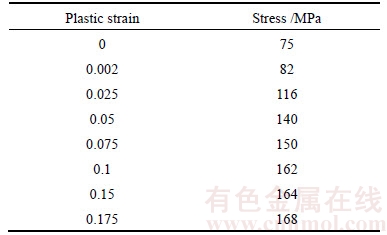
All the tubes studied in this research had the same length of 310 mm and material of aluminum alloy AA6060-T4. Stress�Cstrain data for this material is given in Table 1. The density ��, elastic modulus E, and Poisson ratio �� of the aluminum alloy AA6060-T4 are taken 2800 kg/m2,68200 MPa and 0.3, respectively. A rigid wall of mass m=55.9 kg and of velocity V=13.2 m/s impacted on the conical tubes with different angles ��=0��, 5��, 10��, 15��, 20�� and 30��.
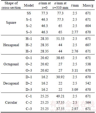
Five different cross section shapes (i.e., square, hexagonal, octagonal, decagonal and circular) and a stiffener in the middle are considered in the present task (see Figure 1(b)). Geometrical specifications of the tubes including side length a and thickness t are presented in Table 2. The parameter x in Table 2 is defined in Figure 1(a), whereas x=0 and 310 mm correspond to the free and clamped ends, respectively.
For more convenient designation of the tubes studied in this research, they are labeled as S�Cr, H�Cr, O�Cr, D�Cr and C�Cr which correspond to square, hexagonal, octagonal, decagonal and circular conical tubes, respectively (see Table 2). Furthermore, r in these designations takes three values of 1, 2 and 3 (more information on this issue has been presented in section 4). The base model mentioned above (straight tube with square cross section) is also labeled as SS (see Table 2).
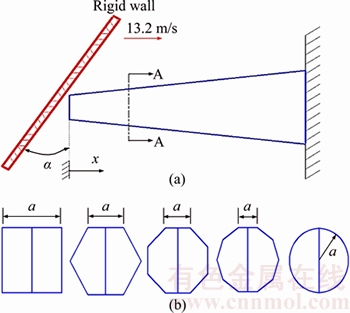
Figure 1 Configuration conical tubes (a) and cross- section (A�CA) shapes (b) of conical tubes subjected to rigid wall
Table 1 Stress�Cstrain data for aluminum alloy AA6060- T4
3 Finite element modeling
Finite element code LS-DYNA was used to study impact analyses of the conical tubes. Before starting the collapse analyses, it was necessary to validate the finite element model. For this purpose, the experiments tested by NAGEL et al [31] on the rectangular tubes under two oblique loadings 10��
Table 2 Geometry specifications of conical tubes
and 30�� were simulated in LS-DYNA. These tubes had length of 199 mm, sectional dimensions of 48.31 mm��79.88 mm and wall thickness of 1.93 mm. The experimental and LS-DYNA results are shown in Figure 2. As seen, the FE analysis correctly predicts the collapse modes, and also the collapse load�Cdisplacement curves obtained from the simulations match well with those of the experiments for both of the impact angles 10��and 30��.
In order to further validate the numerical simulations, the experiments performed by LANGSETH et al [32] on the square tubes with three different thicknesses under various dynamic axial impacts were modeled and analyzed in LS- DYNA, as well. Table 3 indicates both experimental and finite element results in terms of mean dynamic load (Pmd) and rigid wall displacement (��P) together with the error of these results. Mass of the rigid wall used in the experiments is 55.9 kg. The boundary constraints were such that one end of the square tubes was fixed and the other end was attached to the rigid body. As seen in Table 3, the finite element simulations carried out in LS-DYNA are able to predict the rigid wall displacement (��P) and the mean dynamic load (Pmd) with averaged errors of 2.19% and 1.22%, respectively compared to the experimental results. This indicates that the numerically determined mean dynamic load (Pmd) and rigid wall displacement (��P) reasonably agree with the experimental ones. High consistency between the finite element and experimental results allow the authors to run numerical simulations for the conical tubes with different cross sections explained in the section above. All the tubes studied in this research were modeled using Belytschko- Tsay four-node shell elements with nine integration points through the thickness and one integration point in the element plane with the optimal mesh density for all the models being in the order of 4 mm��4 mm.
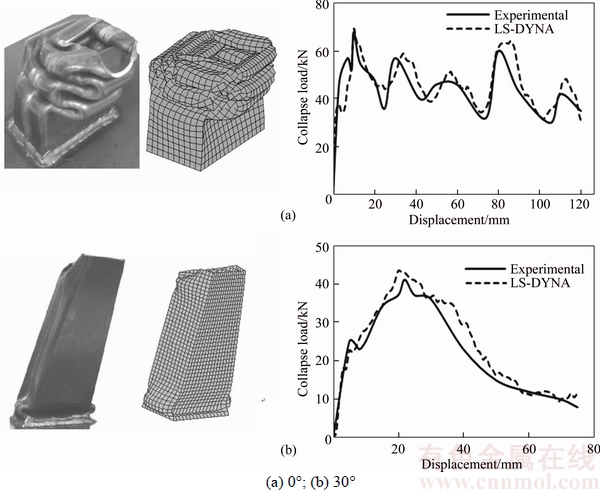
Figure 2 Deformation modes and collapse load�Cdisplacement curves resulted from experiments [31] and LS-DYNA under impact angles:
Table 3 Experimental and LS-DYNA results for square tubes

The rigid body was modeled with one degree of freedom and moved towards the conical tubes along x-axis while its orientation was varied from 0�� to 30��. The rigid-wall velocity was similar to that used in the experimental data [32] and was incorporated into the LS-DYNA model by defining nodal velocities to the rigid body elements. The ��single surface�� type of contact interface was selected to simulate the conical tubes. This contact type uses nodal normal projections and prevents elements from penetrating the wall surfaces during the collapsing of the tube which is dominated by dynamic progressive buckling that manifests itself by the formation of various folds (lobes). In order to define the material properties in LS-DYNA, the material type 24 called MAT_PIECEWISE_ INEAR_PLASTICITY is used. This material type is used to model the elastic-plastic materials.
4 Numerical results and discussion
Collapse behavior of the conical tubes with different sectional configurations described in section 2 was successfully simulated in LS-DYNA. To facilitate the study in forming comparative assessments from the numerical results, it was decided to introduce additional geometric constraints, i.e. all the studied tubes had equal sectional area A and wall thickness t. In addition, the length of all extruded conical tubes was assumed to be 310 mm. Aside from comparing the crashworthiness capacity of these tubes, the main objective of this research was to find their optimum geometries for minimizing their weight. For this purpose, after simulating the tubes labeled as S�C1, H�C1, O�C1, D�C1 and C�C1 (see Table 4), the side length a of these tubes at the distal end (i.e. at x=310mm) was gradually reduced and analyzed in LS-DYNA (considering this important point that their energy absorbing capacity is not significantly compromised) to find the optimum value of the side length a. The results for the optimized tubes labeled as S�C2, H�C2, O�C2, D�C2 and C�C2 are given in Table 4 (only the final results are given for brevity). As is clear, these tubes are lighter than those labeled as S�C1, H�C1, O�C1, D�C1 and C�C1. The obtained optimum values of the side length a together with the values of weight have been presented in Table 2. In the next step, in order to compensate the reduced mass, thickness of these tubes is enhanced to have the tubes with optimum dimensions as well as the same mass. They are labeled as S�C3, H�C3, O�C3, D�C3 and C�C3 (see Table 2). LS-DYNA results for these tubes for different impact angles are presented in Table 4. The change (��Pa (%)) between the obtained mean dynamic load (Pmd) for the conical tubes and square straight tube (labeled as SS) is also given in Table 4. As is clear from Table 4, by employing the conical tubes rather than straight one, energy absorption capacity (Pmd) can be averagely increased by 60%�C123%, dependent on the shape of cross-section. Moreover, the results of ��Pa (%) that the conical tubes are more efficient when they are subjected to oblique loads.
Figure 3 displays the averaged values of mean dynamic load (Pmd) to simply compare the tubes studied in this research in terms of crashworthiness capability. As seen, the double-cell conical tubes work very well for absorbing collision energy compared to the straight tube (SS). In addition, the optimized conical tube with octagonal cross-section (labeled as O-3) is found to absorb more collision energy than other tubes. From Figure 3, it can be also deduced that crashworthiness capacity (Pmd) of the conical tubes with square, hexagonal, octagonal, decagonal and circular cross-sections has been enhanced 19.3%, 14.9%, 33.3%, 39.4% and 28.4%, respectively by optimizing their geometries without changing (or increasing) the mass.
Load�Cdisplacement responses of the optimized structures are given in Figures 4�C8. As is evident in these figures, all the columns have the same behavior, i.e., for the axial loading, the collapse load initially increases with steep slope to reach its peak value, then suddenly decreases and fallows in a number of fluctuations which finally drops to zero due to complete dissipation of the kinetic energy of the rigid-wall by plastic deformations formed in the tubes. As the tubes undergo the oblique crash, the load gradually increases with deflection (which was prominent by increasing the oblique angle) to reach its peak value, and thereafter oscillated several times which finally drops to zero similar to the axial impact. It is worth mentioning that as the impact angle increases, the number of oscillations reduces due to changing the collapse mode from progressive buckling to global buckling. It is well known that each load oscillation corresponds to forming one fold in the tubes. It is also noticed that in comparison to the straight tubes [33], the conical tubes with any cross section are more preferable as they have a stable load�Cdisplacement response and minimize the chances of deformation by buckling.
Table 4 LS-DYNA results for conical tubes with different cross-sections and their comparisons with results of square straight tube

Continued
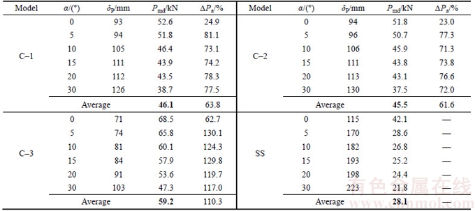
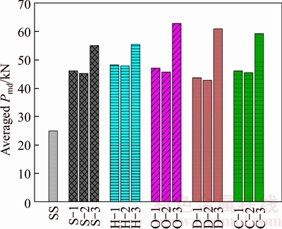
Figure 3 Averaged values of Pmd for tubes
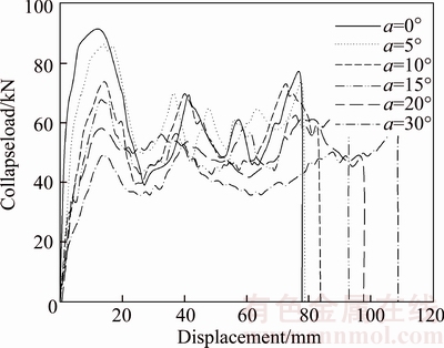
Figure 4 Collapse load�Cdisplacement curves for conical tubes with square section
Deformation modes for the studied double-cell conical tubes with different cross-sections are depicted in Figures 9�C13, from which all of the tubes exhibit progressive folding mode under impact angles 0�� to 10��, while for over impact angle 10��, the global bending mode was gradually added to the folding mode. Such that when the tubes were subjected to 30��, they mostly collapsed in global bending mode. In addition, square and circular tubes show diamond deformation mode; while, the other tubes collapse in concertina mode.
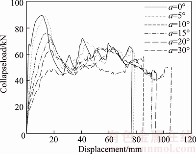
Figure 5 Collapse load�Cdisplacement curves for conical tubes with hexagonal section
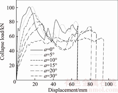
Figure 6 Collapse load�Cdisplacement curves for conical tubes with octagonal section
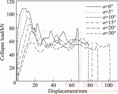
Figure 7 Collapse load�Cdisplacement curves for conical tubes with decagonal section.
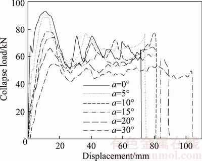
Figure 8 Collapse load�Cdisplacement curves for conical tubes with circular section
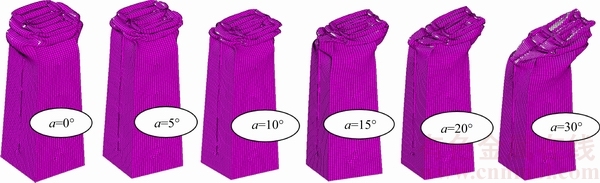
Figure 9 Samples of collapse modes for conical tubes with square cross-section
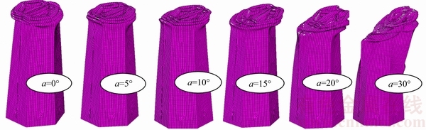
Figure 10 Samples of collapse modes for conical tubes with hexagonal section
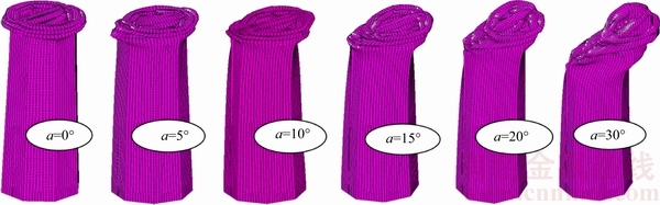
Figure 11 Samples of collapse modes for conical tubes with octagonal section
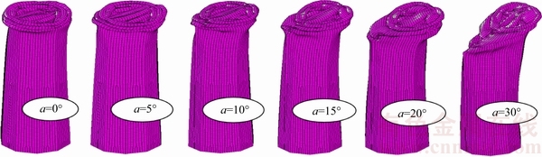
Figure 12 Samples of collapse modes for conical tubes with decagonal section

Figure 13 Samples of collapse modes for conical tubes with circular section
5 Selection of crashworthy energy absorber using TOPSIS
Technique for ordering preferences by similarity to ideal solution (TOPSIS) method was finally used to select the most efficient energy absorbers among the tubes considered in this task. The TOPSIS is known to be a powerful tool for making decision when there are multiple criteria. The mean dynamic load Pmd and the peak force Pmax obtained from the numerical analyses are considered as design criteria herein.
In the TOPSIS method, two artificial alternatives are assumed; ideal alternative and negative ideal alternative. TOPSIS selects the alternative closest to the ideal solution and farthest from the negative ideal alternative. Steps of the TOPSIS method have been explained below:
Step 1: Provide the decision matrix Xij as below:
 (1)
(1)
where, there are m alternatives and n criteria in this matrix, Xij is score of the alternative i with respect to the criterion j.
Step 2: Provide normalized decision matrix Rij as below:
 (2)
(2)
where  for i=1, ��, m; j=1, ��, n; k=1, ��, m. Indeed, this step transforms various criteria dimensions into non-dimensional criteria, which allows comparisons between criteria.
Step 3: Provide the weighted normalized decision matrix Vij as below:
 (3)
(3)
where wi (for i=1, ��, n) is the weight of each criteria, and is determined such that the important criterion takes higher value; meanwhile,
Step 4: Determine the ideal and negative ideal solutions as:
Ideal solution
 (4)
(4)
where vj*={max(vij) if j��J; min (vij) if j��J'}, Moreover, J is the set of benefit criteria (more is better) and J' is the set of negative criteria (less is better).
Negative ideal solution:
 (5)
(5)
where v'={ min (vij) if j��J ; max (vij) if j��J'}.
Step 5: Calculate the separation measures for each alternative. The separation from the ideal alternative is
 , i=1, ��, m (6)
Similarly, the separation from the negative ideal alternative is:
 i=1, ��, m (7)
Step 6: Compute the relative closeness to the ideal solution Ci* as:
 0
0
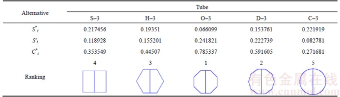
Select the alternative with Ci* closest to 1. In other words, the alternative with highest value of Ci* is selected as the best choice. It is reminded that ranking of the studied tubes by considering only one criterion (or the mean dynamic load Pmd) is given in Figure 2. As well known, the peak force Pmax is another important crashworthiness indicator that is frequently used in the comparative investigations (see Refs.[34, 35]). These two crashworthiness indicators have been calculated at six impact angles; therefore, there exist 12 criteria. Since there are more than one criterion; hence, a method for analyzing the data with various criteria is required. TOPSIS method is therefore implemented on the numerical results for the optimized conical structures. According to the steps mentioned above for the TOPSIS, the decision matrix is constructed as seen in Table 5. It is clear from Table 5 that there exist 5 alternatives and 12 criteria. It is noticed that the peak forces Pmax shown in Table 5 are the first peak loads observed in the load�Cdisplacement curves (Figures 4�C8). The normalized and weighted normalized decision matrixes have been presented in Table 6, respectively. The ideal and negative ideal solutions are calculated in Table 7, and the results of separation measures for each alternative are presented in Tables 8 and 9. The TOPSIS results are shown in Table 10, from which ranking of the studied structures is finally obtained as O�C3, D�C3, H�C3, S�C3 and C�C3. Consequently, applying the tubes with octagonal and decagonal cross-sections in the vehicle structures can significantly contribute to the automobile safety.
6 Conclusions
In this work, numerical study of double-cell conical structures with different sectional configurations for comparing them with square straight tube under dynamic axial and oblique loads is carried out. Many simulations are performed in LS-DYNA, and the following important results are drawn.
Table 5 Decision matrix constructed for optimized conical tubes
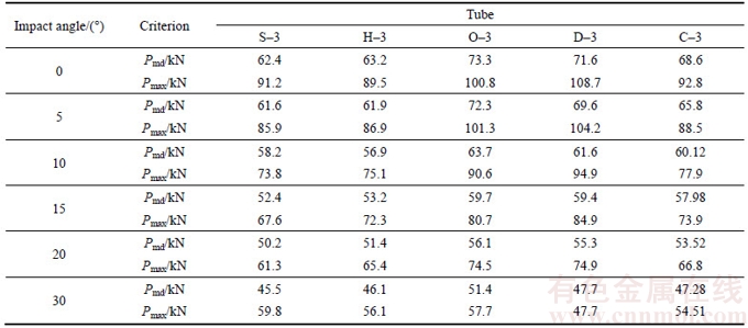
Table 6 Weighted normalized decision matrix
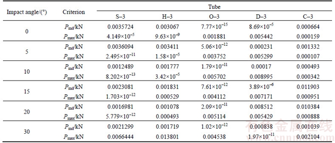
Table 7 Ideal and negative ideal solutions
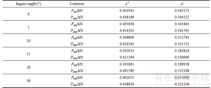
Table 8 Separation measures for ideal alternative negative ideal alternative
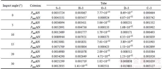
Table 9 Separation measures for negative ideal alternative
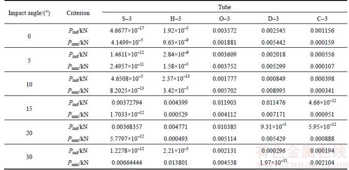
Table 10 TOPSIS results
By employing the conical tubes rather than straight one, energy absorption capacity can be averagely increased 60%�C123% depended on the shape of cross-section. Moreover, the conical tubes are more efficient when they are subjected to oblique loads. Geometry of the conical tubes is optimized by decreasing the cross section dimensions at the distal end while the weight remains unchanged. Energy absorption efficiency is significantly improved further by this optimization. The optimized conical tube with octagonal cross- section is found to absorb more collision energy than other tubes. The tubes exhibit progressive folding mode under impact angles 0��C10��, while a mixed folding and buckling mode is observed for larger impact angles. Furthermore, square and circular tubes display diamond deformation mode; while the other tubes collapse in concertina mode. Based on the TOPSIS results, ranking of the studied structures are finally obtained as O�C3, D�C3, H�C3, S�C3 and C�C3.
References
[1] Shakeri M, Salehghaffari S, Mirzaeifar R. Expansion of circular tubes by rigid tubes as impact energy absorbers: Experimental and theoretical investigation [J]. International Journal of Crashworthiness, 2007, 12: 493�C501.
[2] Kavi H, Toksoy A K, Guden M. Predicting energy absorption in a foam-filled thin-walled aluminum tube based on experimentally determined strengthening coefficient [J]. Material and Design, 2006, 27: 263�C269.
[3] Wang X G, Bloch J A, Cesary D. Axial crushing of tubes made of multi-materials [J]. Mechanics and mechanisms of damage in composites and multi materials. 1991, 1: 351�C361.
[4] Qiu N, Gao Y, Fang J, Feng Z, Sun G, Li Q. Theoretical prediction and optimization of multi-cell hexagonal tubes under axial crashing [J]. Thin Walled Structure, 2016, 102: 111�C121.
[5] Wu S, Zheng G, Sun G, Liu Q, Li G, Li Q. On design of multi-cell thin-walled structures for crashworthiness [J]. International Journal of Impact Engineering, 2016, 88: 102�C117.
[6] Song J, Guo F. A comparative study on the windowed and multi-cell square tubes under axial and oblique loading [J]. Thin Walled Structure, 2013, 66: 9�C14.
[7] Abramowicz W, Jones N. Dynamic axial crushing of square tubes [J]. International Journal of Impact Engineering, 1984, 2: 179�C208
[8] Salehghaffari S, Rais-Rohani M, Najafi A. Analysis and optimization of externally stiffened crush tubes [J]. Thin Walled Structure, 2011, 49: 397�C408.
[9] Chung T E, Lee Y R, Kim C S, Kim H S. Design of aluminum space frame for crashworthiness improvement [J]. SAE Technical Paper, 1996, No.960167. https://doi.org/ 10.4271/960167.
[10] Alexander J. An approximate analysis of the collapse of thin cylindrical shells under axial loading [J]. Mechanics and Applied Mathematics, 1960, 13: 10�C15.
[11] Abramowicz W, Jones N. Dynamic progressive buckling of circular and square tubes [J]. International Journal of Impact Engineering, 1986, 4: 243�C270.
[12] Guillow S, Lu G, Grzebieta R. Quasi-static axial compression of thin-walled circular aluminium tubes [J]. Int Journal of Mechanical Science , 2001, 43: 2103�C2123.
[13] Mamalis A, Manolakos D, Baldoukas A, Viegelahn G. Energy dissipation and associated failure modes when axially loading polygonal thin-walled cylinders [J]. Thin Walled Structure, 1991, 12: 17�C34.
[14] Abramowicz W, Jones N. Dynamic axial crushing of square tubes [J]. International Journal of Impact Engineering, 1984, 2: 179�C208.
[15] Wierzbicki T, Abramowicz W. on the crushing mechanics of thin-walled structures [J]. J Applied Mechanics, 1983, 50: 727�C734.
[16] Chen W, Wierzbicki T. Relative merits of single-cell, multi-cell and foam-filled thin-walled structures in energy absorption [J]. Thin Walled Structure, 2001, 39: 287�C306.
[17] Kim H S. New extruded multi-cell aluminum profile for maximum crash energy absorption and weight efficiency [J]. Thin Walled Structure, 2002, 40: 311�C327.
[18] Zhang X, Cheng G. A comparative study of energyabsorption characteristics of foam-filled andmulti- cell square columns [J]. International Journal of Impact Engineering, 2007, 34: 1739�C1752.
[19] Hosseini-Tehrani P, Pirmohammad S, Golmohammadi M. Study on the collapse of tapered tubes subjected to oblique loads [J]. Journal of Automobil Engineering, 2008, 222(11): 2025�C2039.
[20] Mamalis A G, Johnson W. The quasi-static crumpling of thin-walled circular cylinders and frusta under axial compression [J]. International Journal of Mechanical Science, 1983, 25(9, 10): 713�C732.
[21] Mamalis A G, Johnson W, Viegelahn G L. The crumpling of steel thin walled tubes and frusta under axial compression at elevated stain rates: Some experimental results [J]. International Journal of Mechanical Science, 1984, 26: 537�C548.
[22] Mamalis A G, Manolakos D E, Saigal S, Viegelahn G I, Johnson W. Extensional plastic collapse of thin-walled frusta as energy absorbers [J]. International Journal of Mechanical Science, 1986, 28: 219�C229.
[23] MAMALIS A G, Manolakos D E, Viegelahn G L, Vaxevanidis N M, Johnson W. On the inextensional axial collapse of thin PVC conical shells [J]. International Journal of Mechanical Science, 1986, 28(5): 323�C335.
[24] ALGHAMDI A A A. Reinversion of aluminium frustra [J]. Thin Walled Structure, 2002, 40(12): 1037�C1049.
[25] Alghamdi A A A. Folding-crumpling of thin-walled aluminum frusta [J]. International Journal of Crashworthiness, 2002, 7(1): 67�C78.
[26] ALGHAMDI A A A, ALJAWI A A N, ABU-MANSOUR T M N. Modes of axial collapse of unconstrained capped frusta [J]. International Journal of Mechanical Science, 2002, 44(6): 1145�C1161.
[27] NAGEL G M, Thambiratnam D P. A numerical study on the impact response and energy absorption of tapered thin-walled tubes [J]. International Journal of Mechanical Science, 2004, 46(2): 201�C216.
[28] Nagel G M, Thambiratnam D P. Computer simulation and energy absorption of tapered thin-walled rectangular tubes [J]. Thin Walled Structure, 2005, 43(8): 1225�C1242.
[29] Nagel G M, Thambiratnam D P. Dynamic simulation and energy absorption of tapered thin-walled tubes under oblique impact loading [J]. International Journal of Impact Engineering, 2006, 32(10): 1595�C1620.
[30] Hosseini-Tehrani P, Pirmohammad S. Crashworthiness improvement of longitudinal rail in vehicle structure [C]// 16th Int Conference on Mech Eng. Iran, 2008.
[31] Negal G M, Thambiratnam D P. Dynamic simulation and energy absorption of tapered thin-walled tubes under oblique impact loading [J]. International Journal of Impact Engineering, 2006, 32(10): 1595�C1620.
[32] Langseth M, Hopperstad O. Static and dynamic axial crushing of square thin-walled aluminum Crashworthiness of aluminum extrusions [J]. International Journal of Impact Engineering, 1996, 18(7, 8): 949�C968.
(Edited by FANG Jing-hua)
���ĵ���
��ͬ����˫�����ڶ�̬�����б���غ������µ���ײ��
ժҪ��Ϊ��߽ṹ�İ�ȫ�ԣ����ڹ�Խ��Խ���Ӧ����������ҵ�������о�˫�����ڶ�̬�����б���غ������µ�ʧЧ��Ϊ��������LS-DYNA��֤������Ԫģ�ͶԲ�ͬ����(Բ�Ρ����Ρ������Ρ��˽��Ρ�ʮ����)�ܲĵ���ײ�Խ�������ֵ������Ȼ��ͨ������Զ�˽���ߴ����Ż��ܵļ�����״��ͬʱ�����������䡣����������˽���Բ�ιܱ������ܸ��ʺ�����ײ���������������ܺ�Բ�ܳ��ֽ��ʯ����ģʽ���������ܳ��߸�ʽʧЧ������TOPSIS���߷���������ֵ�������ѡ������Ч����������
�ؼ��ʣ���ײ�ԣ���̬�����б���غɣ�˫���ܣ�ƽ�����غ�
Foundation item: Project(660) supported by University of Mohaghegh Ardabili, Iran
Received date: 2016-12-13; Accepted date: 2017-03-23
Corresponding author: Pirmohammad Sadjad, PhD, Assistant Professor; Tel: +98�C45�C3351�C7030 ; E-mail: s_pirmohammad@uma.ac.ir; ORCID: 0000-0003-1988-1058

