J. Cent. South Univ. Technol. (2010) 17: 1087-1094
DOI: 10.1007/s11771-010-0601-6

Simplified design of rock cavern concrete lining to resist shock loading
ZHAO P J1, LOK T S2, YIN Zhi-qiang(��־ǿ)3, ZHOU Zi-long(������)3
1. Butler Partners Pty Ltd, Queensland 4006, Australia;
2. Protective Technology Research Centre, School of Civil and Environmental Engineering,
Nanyang Technological University, Singapore 639798, Singapore;
3. School of Resources and Safety Engineering, Central South University, Changsha 410083, China
? Central South University Press and Springer-Verlag Berlin Heidelberg 2010
Abstract: A simplified method was proposed for the design of concrete lining in underground rock cavern/tunnel against shock loading. The loading may result from the detonation of explosives on ground surface or ground penetration projectiles exploding adjacent to the cavern/tunnel. The resulting problem necessitates the solution of the dynamics of a beam loaded by a transient pressure uniformly distributed over the span. According to mechanical characteristics of the system with rock bolt and shotcrete, a dynamic support design method based on equivalent single degree of freedom (SDOF) was put forward. The SDOF method was applied to obtaining the maximum displacement at the mid-span of the beam, which is often the controlling factor in the blast-resistant design. In the formulation of the problem, the proposed method combines the phenomena of spalling and structural dynamics theory. An example is provided to demonstrate the applicability of this simplified method.
Key words: tunnel lining design; shock loading; dynamic response; rock cavern
1 Introduction
Most of the countries in the world try to exploit more resources from their scarce lands. The optimum option for overcoming the demand for lands and space is to construct underground rock caverns. The major problem in underground space development is the design of support system aiming to stabilize the surrounding rock mass to resist various expected loadings in the long run.
Wire mesh (or steel fibre, or both) reinforced shotcrete in combination with rock bolts or rock cables is widely used as the support system in rock caverns and tunnels. Conceptually, the rock bolts provide global reinforcement by keeping the integrity of the surrounding rock by forming a self-supporting arch in heavily-jointed rock mass, while the shotcrete layer provides support to the unstressed loose rock fragments between the adjacent rock bolts [1]. An approach was suggested by BARRET and MCCREATH [2] to design rock bolt and shotcrete support system by assuming a triangular loose rock zone between the rock bolts and four possible failure mechanisms of shotcrete. Their analyses showed that shotcrete failure was always due to excessive bending moment instead of shear stress.
Because of numerous complexities, current design methods are primarily based on engineering practive [3]. For example, BIENIAWSKI [4] commented shotcrete thickness for different rock mass ratings (RMR), and GRIMSTAD and BARTON [5] proposed a design chart relating different support systems to the tunnelling quality index (Q value). Conversely, numerical methods have been used to study the complicated interaction between surrounding rock and support system. HOEK and DIEDERICHS [3] presented simulation from a numerical code (PHASES) of a 4-m span tunnel. The results confirm that the support system does not prevent rock failure, but it has the ability of containing the dead weight of the fragmented rock. CHRYSSANTHAKIS et al [6] adopted the universal distinct element code (UDEC) to investigate the overall stability and the effect of combined application of rock bolts and steel fibre reinforced shotcrete for a 3-lane traffic tunnel with 16 m in span and 10 m in height, while LOK et al [7] used the UDEC code to analyse the effect of steel fibre reinforced shotcrete lining on the stability of a rock cavern subjected to explosive load. In general, numerical analysis is a complicated process which can yield useful results, only when detailed and accurate input data are provided. Especially, the situation becomes more complicated when the loading is caused by the detonation of explosives on ground surface or ground penetration projectiles exploding adjacent to the support system. Therefore, it is not often treated as a practical design approach.
At present, in the method of structural aseismic design, the pushover analysis is introduced into the structural aseismic design code for many countries. In this analysis, it is the problem that the confirmation of the target displacement of the structure needs to be solved. The target displacement of structural refers to the equivalent single degree of freedom (SDOF) system in the impact loading obtained from non-linear time-history analysis of the maximum displacement. The judgment of structural instability or complete fracture is accepted by engineers through method of maximum displacement response of an equivalent SDOF elasto-plastic system. FISCHER and HARING [8] studied the factors influencing SDOF system based on the impacts on structures caused by shock loading. In terms of energy, TERAN et al [9] comprehensively took the factors, related with the design of structure seismic, affecting structure stress and deformation into consideration. Based on Timoshenko��s beam theory and finite difference methods, KRAUTHAMMER et al [10] put forward the numerical analysis for various failure modes of reinforced concrete beams and simplified analysis for single degree of freedom. RUIZ-GARCIA and MIRANDA [11], and CHOPRA and CHINTANAPAKDEE [12] presented a series of results of statistical studies aiming at increasing engineering comprehension of the implications and effectiveness of the ratio of the maximum inelastic to the maximum elastic displacement for SDOF systems to analyse the structural behaviour in the short period range.
This work focused on analysing the design of support system consisting of rock bolts and reinforced shotcrete lining against the spalling induced by shock loading. After simplification, the problem was converted into a simple beam subjected to uniformly distributed transient pressure, and solved by using an equivalent SDOF method. It overcomes the shortcoming that carrying-capacity-based design cannot include the factor of elastic-plastic displacement and can fully reflects the influence exerted by shock loading on structures.
2 Description of design model
For the current rock bolt and shotcrete support system, the rock bolts provided the global reinforcement by keeping the integrity of the rock mass, while the shotcrete lining provided support to the broken rock blocks between the adjacent rock bolts [13]. Since the shear resistance of shotcrete lining is higher than the bending resistance, it is assumed that the failure mechanism in the design is the bending mode.
Consider the design model shown in Fig.1, which is subjected to a one-dimensional shock wave loading. The assumed one-dimensional triangular compressive wave propagates towards a typical segment of rock bolts and shotcrete support system which is simplified as a beam but simply-supported at the ends by rock bolts. This is a conservative assumption because in a real system, the beam is stiff without rotation at the supports. The incident compressive wave is transformed into a tensile wave by reflection on the free surface of the shotcrete lining layer. The tensile wave is superimposed into the incident compressive wave as it propagates back into the rock mass. The total stress is the sum of the incident and reflected stresses.
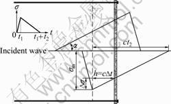
Fig.1 Design model of rock bolts and shotcrete lining system
Consider the stress state near the free surface. In the initial stage of reflection, the incident compressive stress is stronger than the reflected tensile stress. Therefore, the total stress is compressive. No damage will occur provided the strength of rock mass is higher than the loading. After the incident stress reaches the peak value on the free surface, the peak tensile stress of the reflected wave meets the fading incident compressive wave during its propagation in the rock mass. The rock mass is now applied with resultant tensile stress as the reflected wave propagates further into the rock mass. A layer of rock mass will spall when the tensile stress exceeds the tensile strength of the rock. The thickness of the spalled rock layer is determined by the characteristics of both the incident wave and the rock mass.
The spalled rock layer has a certain initial velocity and will separate from the rest of the rock mass. The motion of this rock layer must be resisted by the ��beam element�� consisting of the shotcrete lining supported by the rock bolts.
One-dimensional wave theory gives a flat fracture surface parallel to the lining layer. As a result, the spalled rock layer and the lining layer form a composite beam with possible shear slip along their interface. This problem is beyond the practical manipulation in design process. Therefore, to simplify the problem, it is assumed that the spalled rock layer is fragmented into small pieces with zero flexural stiffness and strength. However, it increases the mass density of the beam and applies an additional inertial load to the beam. Although this assumption is conservative, it is applicable to the heavily-jointed rock mass.
The reinforced shotcrete beam carrying the spalled rock mass continues to move, but it is decelerated by the resistance of the bolts; the supporting ends are assumed to remain intact. If the beam remains intact when its motion terminates, the support system is considered to be adequate. Then, the design criterion is developed according to the capacity of the beam subjected to the prescribed dynamic load.
3 Formulation of dynamic problem for simple beam
The first stage is to determine the thickness of the spalled rock layer and the initial velocity of the beam. The shotcrete lining layer is relatively thin and its normal stress is low, so it is assumed that the interface between the rock mass and the lining layer is a free surface. This assumption decouples the interaction between the rock mass and the lining layer. It enables the calculation of the location of the fracture surface without considering the presence of the lining layer.
Referring to Fig.1, angle a is calculated as:
 (1)
(1)
where sm is the peak stress of the incident wave; t2 is the time duration of the decreasing portion of the incident wave; and c is the wave velocity of the rock mass.
The maximum tensile stress  is the difference between the reflected stress and the incident stress where the peak reflected stress occurs. It is calculated as:
 (2)
(2)
where Dt is the time interval from the time when the peak stress reaches the free surface to the current time.
When the maximum tensile stress reaches the tensile strength of the rock mass, failure of the rock occurs and the outer rock layer is detached. Time interval Dt may be calculated as:
 (3)
(3)
where  is the tensile strength of the rock mass.
The thickness of spalled rock layer h is therefore determined as:
 (4)
(4)
From Eq.(4), it is seen that the thickness of the spalled rock is a function of parameters t2, and sm. This thickness will become very large for the combination of large t2,and low sm. In the practice, complete detachment of a very thick planar rock layer is unlikely to occur because of two-dimensional effect. So this design method is applicable to a relatively thin layer of spalled rock mass.
The particle velocity in the rock mass is the sum of the contributions from both the incident wave and the reflected wave:
 (5)
(5)
where r is the density of the rock mass, sR and sI are the absolute stresses of the reflected and incident waves, respectively.
On the fracture surface, sR and sI are known to be:
 (6)
(6)
 (7)
(7)
Substituting Eqs.(6) and (7) into Eq.(5) gives the initial velocity of detached rock mass as:
 (8)
(8)
It is assumed that the rock bolts are strong and the connection between the rock bolts and the lining layer is rigid. Therefore, the velocity of the supporting ends of the beam will simultaneously be with the rock bolts, while the beam body will develop inertial motion. The support velocity is a function of time expressed as:
 (9)
(9)
where the origin of t is taken as the time when the fracture surface is formed, and td is the time difference of the time duration of the decreasing portion of the incident wave and the time interval from the time when the peak stress reaches the free surface to the current time, which is calculated from:
 (10)
(10)
The above derivation shows that the key to the problem is to study the beam motion under initial velocity v0 and subjected to the deceleration of the support ends. This problem can be resolved into two components as shown in Fig.2. The first component is the rigid-body motion with uniform velocity v0 over the whole beam. The second is the beam motion caused by the support movement while the initial beam velocity is zero. The velocity of the support movement, which is in the opposite direction of v0, is the difference between v0 and v1(t), defined by Dv(t) and is expressed as
 t��td (11)
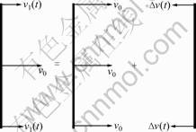
Fig.2 Decomposition of beam motion
Furthermore, beam motion due to the support movement can be solved by further decomposing it into two parts: the quasi-static motion, which is a rigid-body motion at the support velocity, and the deformational motion due to an equivalent uniform pressure determined by support acceleration. The deformational motion is illustrated in Fig.3.
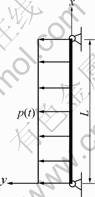
Fig.3 Equivalent distributed load in deformational motion
Equivalent distributed load p(x, t) can be determined from conventional structural dynamic principles.
The assumption of the static influence functions may be written as
 (12)
(12)
 (13)
(13)
where x is the spatial coordinate starting from the bottom end, and L is the full length of the beam (equal to the bolt spacing).
The equivalent load density is calculated according to

 (14)
(14)
where p0 is defined as:
 (15)
(15)
m is the mass per unit length of the beam including the spalled rock layer and calculated from:
 (16)
(16)
in which hB and rB are the thickness and density of the lining, respectively.
The equivalent load is negative, indicating that this load points to the right. Clearly, the inertial effect of the beam maintains the beam at a constant velocity rightwards while the two ends are decelerated with the rock bolts. This action gives rise to deflection and bending in the beam. The first two motions are both rigid-body motion and do not cause any bending moment in the beam. Therefore, failure of the beam is controlled by the deformational response, which is characterized by an equivalent pressure given by Eq.(14).
The deformational motion is described by the following governing equation, boundary conditions and initial condition:
 (17)
(17)
where u=u(x, t) is the deflection, E and I are the elastic modulus and the second moment of area of the beam cross-section, respectively.
4 Solution of mid-span deflection�CSDOF method
The problem described by Eq.(17) can be solved by the standard modal decomposition method if the beam remains linear elastic. However, the solution is relatively complex if the beam yields during motion. For design purpose, we only need to know the maximum deflection at mid-span. So, the detailed variation of deflection in the time domain is unnecessary and an approximate maximum mid-span deflection can be conveniently obtained by the simplified equivalent SDOF method when the beam is subjected to a uniformly distributed pressure existing for a short duration.
As shown in Fig.4, the dynamic response of the beam is approximated by the forced motion of an equivalent SDOF system. Its displacement represents the deflection at mid-span of the beam. Equivalent parameters are determined by appropriate transformation factors obtained by solving the beam motion governed by certain assumed mode shapes. Often, the dynamic mode shape for shock-type loading is the same as the static mode shape under the same support and load conditions.
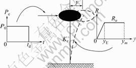
Fig.4 Equivalent SDOF system
The parameters of the equivalent SDOF system depend on the structure type, and load and support conditions. For a simply-supported beam under uniform pressure load, the equivalent parameters can be determined from Table 1 [14]. In Table 1, Mp, I and L are the ultimate bending moment, moment of inertia of the cross-section and span of the beam, respectively; and KL and KM are the load factor and mass factor, respectively. For the simply-supported beam, KL and KM have values of 0.64 and 0.50 in the elastic range, and 0.50 and 0.33 in the plastic range.
Table 1 Parameters of equivalent SDOF system
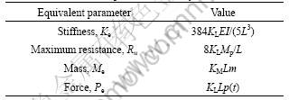
Using these equivalent parameters, the equation of motion of the equivalent SDOF can be written as
 (18)
(18)
where Me is the lumped mass; R(y) is the restoration force and Pe(t) is the external force. Assuming elastic-perfectly plastic response of the beam in flexure, the equivalent spring resistance R=R(y) in the above equation is linearly proportional to the displacement with stiffness Ke for y��yE and takes a constant Ru thereafter, which may be written as
 (19)
(19)
where yE is the maximum elastic displacement and can be calculated as
 (20)
(20)
The external force Pe(t) follows the same variation with time as the equivalent pressure, namely:
 (21)
(21)
where P0 is the peak equivalent external force, which is calculated, according to Eq.(14), as:
 (22)
(22)
The motion of the equivalent SDOF system can be solved and the maximum displacement determined. The solution is often expressed in terms of the ductility ratio, which is defined as the ratio of the maximum displacement to the maximum elastic displacement. It can be shown that the ductility ratio is a function of two non-dimensional parameters and can be written as
 (23)
(23)
where ym is the maximum displacement and T is the natural period of the system and calculated from:
 (24)
(24)
The ductility ratio is solved and presented in the form of a design chart shown in Fig.5 for different non-dimensional system parameters. Thus, the maximum deflection at mid-span, which is equal to the maximum displacement of the equivalent SDOF system, can be determined according to the maximum elastic displacement and ductility ratio.
In reinforced concrete design, the controlling parameter is the support rotation angle calculated from
 (25)
(25)
The beam is considered as unsatisfactory if the support rotation exceeds a critical value.
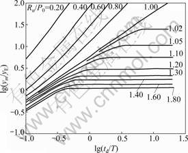
Fig.5 Solution of ductility ratio for uniformly distributed constant transient load
5 Example
An example is given to show the step-by-step procedure of the proposed method to design reinforced shotcrete lining of a certain thickness and rock bolt spacing. The parameters are shown in Table 2.
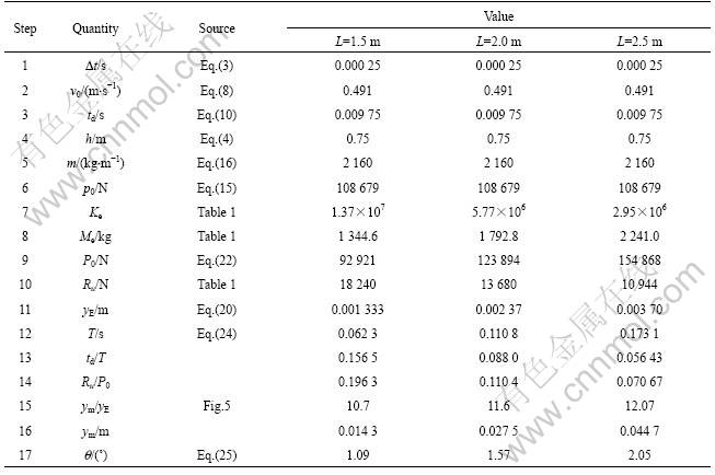
Three lining thicknesses of 75 100 and 150 mm are considered for a spacing of 2.5 m. In addition, three spacing of 1.5, 2.0 and 2.5 m are considered for the fixed beam thickness of 75 mm. The given ultimate bending moment is close to the theoretical value of the reinforced concrete beam of the particular depth with reinforcement
Table 2 Parameters of example
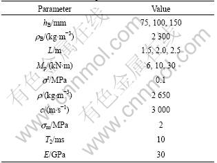
ratio of about 0.5%. The results are shown in Tables 3 and 4.
The support rotation angle decreases with increase in lining thickness and reduction in rock bolt spacing [15]. This is consistent with the physical nature of the problem. The 2.05? support rotation of the 75 mm-thick lining of 2.5 m spacing is acceptable according to the design criterion for reinforced concrete elements. At this rotation angle, the beam is in the medium response region and will not collapse completely. Clearly, the 75 mm-thick reinforced shotcrete lining is acceptable according to the commonly accepted criterion in blast- resistant design of reinforced concrete members.
Table 3 Design calculation results for various parameters at 2.5 m spacing
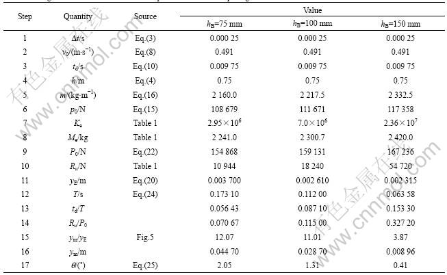
Table 4 Design calculation results for various parameters at 75 mm thick lining
6 Conclusions
(1) A rational design method is proposed for the current rock bolt and shotcrete support system of a rock cavern against spalling caused by shock loads based on a simplified mechanical model, relevant assumptions on characteristics of rock damage mechanism and interactions of support system.
(2) This shotcrete/rockbolt support system design method combines two most important structural design parameters about the loading and displacement based on a simplified mechanical model analysis of the shock loading. The calculation steps of the design method are demonstrated. An example is provided. The results indicate that the proposed method provides a reasonable estimate of the response.
(3) This design method is able to account for the primary failure mechanism of the support system and adhere to a step-by-step procedure for engineers to consider at each phase. Complex numerical calculations are avoided in the design methods. So, it is a simplified design method which can fully satisfy the accuracy in engineering.
Acknowledgement
The authors wish to acknowledge the financial support provided by the Defense Science and Technology Agency (DSTA) of Singapore. They are also grateful to the Director, DSTA, for permission to publish the paper.
References
GLAMHEDEN R, CURTIS P. Excavation of a cavern for high-pressure storage of natural gas [J]. Tunnelling and Underground Space Technology, 2006, 21(1): 56-67.
BARRETT S V L, MCCREATH D R. Shotcrete support design in blocky ground: Towards a deterministic approach [J]. Tunnelling and Underground Space Technology, 1995, 10(1): 79-89.
HOEK E, DIEDERICHS M S. Empirical estimation of rock mass modulus [J]. International Journal of Rock Mechanics and Mining Sciences, 2006, 43(2): 203-215.
BIENIAWSKI Z T. Engineering rock mass classifications [M]. New York: John Wiley and Sons Inc, 1989: 51-72.
GRIMSTAD E, BARTON N. Updating the Q-system for NMT [C]// BERG K O. Proceedings of the International Symposium on Sprayed Concrete��Modern use of wet mix sprayed concrete for underground support. Oslo: Norwegian Concrete Association, 1993: 46-66.
CHRYSSANTHAKIS P, BARTON N, LORIG L, HRISTIANSON M, Numerical simulation of fiber reinforced shotcrete in a tunnel using discrete element method [J]. International Journal of Rock Mechanics and Mining Science, 1997, 34(3/4): 578-588.
LOK T S, ZHAO P J, LI XI-BING, LIM C H. Discrete element modeling of shotcrete-lined rock cavern subjected to shock loading [C]// Proceeding of the 8th East Asia-Pacific Conference on Structural Engineering and Construction. Singapore: 2001: 839-845.
FISCHER K, HARING I. SDOF response model parameters from dynamic blast loading experiments [J]. Engineering Structures, 2009, 31(8): 1677-1686.
TERAN G A, AVILA E, RANGEL G. On the use of plastic energy to establish strength requirements in ductile structures [J]. Engineering Structures, 2003, 22(7): 965-980.
KRAUTHAMMER T, ASSADI-LAMOUKI A, SHANAA H M. Analysis of impulsively loaded reinforced concrete elements��I theory [J]. Computers and Structures, 1993, 48(5): 851-860.
RUIZ-GARCIA J, MIRANDA E. Inelastic displacement rations for design of structures on soft soil sites [J]. Structural Engineering,2004, 130(12): 2051-2061.
CHOPRA A K, CHINATANAPAKDEE C. Inelastic deformation ratios for design and evaluation of structures: Single-degree-of- freedom bilinear systems [J]. Journal of Structural Engineering, 2004, 130(9): 1309-1319.
MALMGREN L, NORDLUND E. Interaction of shotcrete with rock and rock loolts��A numerical study [J]. International Journal of Rock Mechanics and Mining Science, 2008, 45(4): 538-553.
FERTIS, D G. Dynamics and vibration of structures [M]. New York: John Wiley and Sons Inc, 1973.
AS/NZS 1170.4. Structural design actions, Part 4: Earthquake actions. Volume 2��Commentary [S].
(Edited by YANG You-ping)
Foundation item: Projects(50934006, 50904079) supported by the National Natural Science Foundation of China; Project(2010CB732004) supported by the National Basic Research Program of China
Received date: 2010-01-05; Accepted date: 2010-04-13
Corresponding author: ZHAO P J, PhD, Senior Engineer; Tel: +61-7-38523800; E-mail: pzhao@butlerpartners.com.au

