
Surface behavior of pasted nickel electrodes with
electrodeposited Co-Ce on substrate
WANG Dian-long(王殿龙), WANG Chun-yu(王春雨), DAI Chang-song(戴长松), JIANG Zhao-hua(姜兆华)
Department of Applied Chemistry, Harbin Institute of Technology, Harbin 150001, China
Received 9 November 2005; accepted 6 April 2006
Abstract: MH/Ni battery for electro-vehicle has become a hot topic of studies. The Co-Ce alloys were electrodeposited on the nickel substrate to modify pasted nickel electrode substrate. SEM and XRD results show that the surface of the substrate contains Co(OH)2 and CoOOH film, and CV shows that modified film can improve electron conductivity capability. The state of charge (SOC) or state of discharge (SOD) curves indicate that Co-Ce modified substrate can enhance Ni electrode charge and discharge performance at high rate. The surface analysis by XPS shows that, the Co(Ⅱ)/Co(Ⅲ) ratio is 76.80/23.19 at the SOD, but the Co(Ⅱ)/Co(Ⅲ) ratio is 57.79/42.21 at the SOC, which indicates that the conductibility of electrodeposited Co-Ce alloys on the nickel substrate is enhanced because CoOOH and Co(OH)2 are created on the substrate surface. The modified surface with CoOOH and Co(OH)2 can enhance the conductibility of electrons between the substrate and active materials, and improve the high rate SOC and SOD ability.
Key words: nickel electrode; substrate modification; Co-Ce alloys; surface
1 Introduction
MH/Ni batteries have supper specific energy density, better performance of charging and discharging, and are friendly to the surroundings. So, MH/Ni batteries have been applied widely in power tools[1]. The design of MH/Ni batteries is limited by positive electrode, and Ni electrode performance restricts the enhancement of batteries capability. From the reports on Ni electrodes modification, there are lots of studies focused on active materials and additive of Ni electrode[2, 3], but few are focused on substrate modification. The consumed layer near the nickel foam and the inborn Ni(OH)2/NiOOH semiconductor film on the surface of nickel foam restrict the performance of discharging at high rate[4]. The literatures[5-7] show that the Ni electrode modification is focused on active materials surface, but substrate modification has been rarely researched. In order to enhance the MH/Ni battery’s discharging performance at high rate, the nickel foam needs to be modified. Improving collection conductibility is an efficient method to improve the MH/Ni battery’s specific energy density and specific power density[8, 9].
Adding rare earth can realize the Ni electrode modification[10, 11], and Ni electrode modification with electrodeposited cobalt on the substrate has already been reported[12]. This paper explained a modified method that electrodeposited Co-Ce alloys on the substrate to modify Ni electrode. In order to investigate the mechanism of Co-Ce alloys, we adopted bare nickel board to simulate bare nickel foam electrodeposited Co-Ce, and the crystal microscopy, species, chemical composition of cobalt at the state of charge (SOC) or state of discharge(SOD) surface were analyzed, and the transformation laws were studied. The process of electrodepositing Co-Ce is referred to Ref.[12].
2 Experimental
The size of nickel substrate in this experiment was 35 mm×35 mm×0.25 mm. The mass ratio of active materials Ni(OH)2?CoO?Ni powder: CMC (3.1%)? PTFE(2.6%)=150?10.5?7?4?3. The deion water was used. The active material quantities of every Ni electrode samples are similar after drying, pressing, cranking out the pasted nickel electrode. The two sintered cadmium electrodes were prepared for negative ones, whose theoretical capacities are more than 150% that of positive ones, in order to eliminate negative impaction. The electrolyte was 6 mol/L KOH and 15 g/L LiOH. The positive and negative electrodes were secluded by septum, clamped with splints, prepared into the similar simulated batteries. The battery was aged in the electrolyte for more than 12 h.
The formation test and charge-discharge cycle test were carried out by the BTS-5 V/10 A precision battery testing system. The formation rule was: charging at 0.1C rate to 150% theoretical capacity, holding for 10 min, then discharging at 0.1 C rate to 1.0 V (vs Cd/Cd(OH)2), cycling for 5 times; then charging at 0.2 C rate to 150% theoretical capacity, holding for 10 min, discharging at 0.2 C rate to 1.0 V(vs Cd/Cd(OH)2), cycling for 10 times.
After formation, one battery was charged by 100% and the other was discharged to 0%. The Ni electrodes were off-loaded, and the substrate was cleared up with ultrasonic, then dried in the air. The substrate sample was prepared. Scanning electron microscope (SEM) images were collected using a Japanese HITA CHI S-4700; X-ray photoelectron spectroscopy (XPS) patterns were taken using an American PIH5700 ESCA; X-ray diffraction(XRD) patterns were tasted using an England Bede D’ with Cu Kα radiation.
3 Results and discussion
3.1 First formation contrast curves and charge- discharge performance of Ni electrode
There are various redox reactions in the process of formation, and the Ni electrode of porosity substrate with electrodeposited Co-Ce has more reactions than the Ni electrode of bare nickel substrate. We can observe contrast curves of the first charge at 0.1 C rate during formation.
Fig.1 indicates that the substrate with electro- deposited Co-Ce has three voltage stages: the first stage around 0.2 V (vs Cd/Cd(OH)2), the second stage around 1.0 V(vs Cd/Cd(OH)2), and the third stage around 1.45 V (vs Cd/Cd(OH)2); but the Ni electrode of bare nickel substrate only appears in one stage at 1.45 V (vs Cd/ Cd(OH)2).
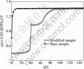
Fig.1 First formation charge curves of Ni electrode at 0.1 C rate on Co-Ce modified substrate and bare nickel substrate
As the redox reaction voltage on the positive and negative electrodes in the alkalescency is 
 and the excessive voltage of electrode polarization is falling potential on the resistance. We can conclude that the first voltage stage corresponds to the reversible redox reactions:

The second charging stage is the same as that of CoO additive in the active materials oxygenated to the CoOOH[13], and the electrochemical reaction is

The second stage descends from 1.0 V, because the created CoOOH improves the electron conductivity. That phenomenon is the same as additive CoO in the active materials. The third charging stage corresponds to the Ni(OH)2 transformation of NiOOH in the active materials.
The cobalt oxidation stage vanishes after many charge-discharge cycles, which indicates that the reaction is not reversible in this experiment. That phenomenon is validated in the experiment of cyclic voltammetry (CV). The CV curves of Co-Ce modificated nickel foam can approach SOC or SOD of battery. Fig.2 shows the CV curve of the 110 PPI nickel foam with electrodeposited Co-Ce as electrode, in the electrolyte 6 mol/L KOH and LiOH 15 g/L, with the scanning rate of 2 mV/s. The CV curve indicates that it has Co/Co(OH)2 oxidation peak and deoxidation peak. The Co(OH)2/CoOOH oxidation peak appears, but the Co(OH)2/CoOOH deoxidation peak does not appear. This phenomenon indicates that the ability of CoOOH deoxidizing Co(OH)2 is very weak. The amount of CoOOH can be increased along with the charge-discharge cycles.
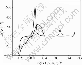
Fig.2 CV curve of nickel substrate with electrodeposited Co-Ce
The charge and discharge curves of the bare nickel electrode are contrasted with those of the modified nickel electrode by electrodepositing Co-Ce at 7 C rate, as shown in Fig.3. The curves indicate that the charge acceptance ability of the modified Ni electrode at high rate and discharge specific capacity are improved clearly.
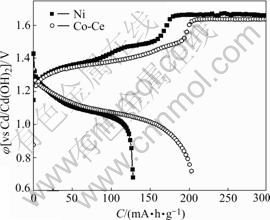
Fig.3 Charge-discharge curves of nickel electrodes at 7 C rate after formation
The result shows that the cobalt chemical composition is changed on the electrodeposited Co-Ce substrate during charge and discharge. The interface between the substrate and active materials creates Co(OH)2 and CoOOH film, which improves electron conductivity capability, enhancing charge or discharge ability at high rate.
3.2 Surface morphology and compositions
3.2.1 SEM examination
The content of cerium is 0.19%(mass fraction) in the electrodeposited Co-Ce alloys film, and the morphology of the crystal grain is spicular, as shown in Fig.4. Compared with bare nickel foam, the modified substrate has more interface area between the active materials and substrate, as shown in Fig.5. After the formation of the modified Ni electrode, it has spicular grain still; and the amount of spicular grain at SOC is more than that at SOD, as shown in Fig.6 and Fig.7. The variety of crystal grain microscopy indicates that substrate surface has phase transformation during charge and discharge processes. We can conclude that this phase transformation improves the performance of nickel electrode.
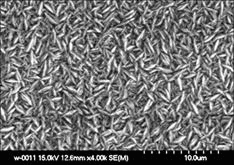
Fig.4 SEM image of electrodeposited Co-Ce
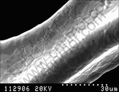
Fig.5 SEM image of bare nickel foam
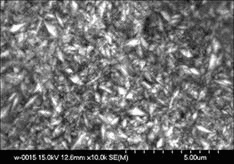
Fig.6 SEM image of electrodeposited Co-Ce on substrate at SOD
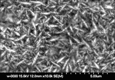
Fig.7 SEM image of electrodeposited Co-Ce on substrate at SOC
3.2.2 XPS characterization
X-ray photoelectron spectra are collected by using a Leybold LH X1 spectrometer using unmonochromatized Mg Kα radiation(1253.6 eV) operating at 13 kV and 20 mA. The binding energy (BE) is calibrated with respect to the Co 2p signals. Spectra are recorded only after the wide scan showing that no feature arises from the cobalt tape and from the sample rod. Wide spectra are collected in fixed analyzer transmission mode with a passing energy of 187.85 eV, and detailed spectra are collected in fixed analyzer transmission mode with a passing energy of 29.35 eV. The Ar+ ion bombardment at 4 keV is used for the depth profile measurement and SiO2/Si is used as a reference to estimate the sputtering rate. The C 1s peak at 284.62 eV is used to calibrate peak positions. All samples after formation are washed thoroughly with ultrasonic in distilled water and dried before executing the spectroscopic analysis.
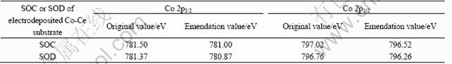
After formation, the Co-Ce substrate has peak of Co and Ni, as shown in Fig.8 and Fig.9. The Co 2p detailed spectra are shown in Fig.10 and Fig.11, respectively. The C 1s peak is at 285.12 eV, and the peak displacement is 0.5 eV. Table 1 lists the XP spectra data.
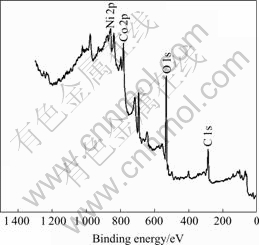
Fig.8 XP spectrum for discharge on electrodeposited Co-Ce substrate

Fig.9 XP spectrum for charge on electrodeposited Co-Ce substrate

Fig.10 XP detailed spectrum of Co 2p region for discharge on electrodeposited Co-Ce substrate
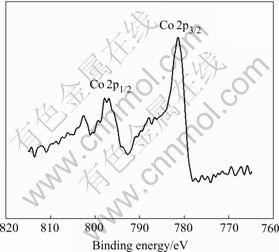
Fig.11 XP detailed spectrum of Co 2p region for charge on electrodeposited Co-Ce substrate
Table 1 Binding energy of Co 2p peaks of SOC or SOD
To examine the chemical composition of the oxide layer, and a relative amount of Co(Ⅱ) or Co(Ⅲ), the curve fitting of the Co 2p1/2 spectra shows an intense peak and a distinct satellite, but a detailed analysis of the Co2p1/2 shake-up structure [14], as shown in Fig.12 and Fig.13.
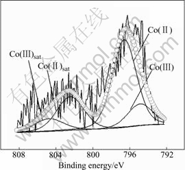
Fig.12 XP detailed spectra of Co 2p1/2 region for SOD on electrodeposited Co-Ce substrate
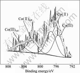
Fig.13 XP detailed spectra of Co2p1/2 region for SOC on electrodeposited Co-Ce substrate
Detailed XPS experiment and the relevant curve fitting are performed. The ratio, which is the main peak area of Co(Ⅱ) adding to its satellite area and the main peak area of Co(Ⅲ) adding to its satellite area, can discriminate the repetitive amount of Co(Ⅱ) and Co(Ⅲ). At the SOD, the Co(Ⅱ)/Co(Ⅲ) ratio is 76.80/23.19, but at the SOC, the Co(Ⅱ)/Co(Ⅲ) ratio is 57.79/42.21.
The result shows that the amount of Co(Ⅱ) of SOD is excessive compared with that of SOC, which indicates that the phase transformation takes place during charge and discharge processes. However, on the first charging curve of formation, when Co(OH)2 reacts to CoOOH, the relative dispersion voltage of the Ni electrode and the negative voltage must exceed 1.0 V (vs Cd(OH)2). So we can conclude that Co is transformed to Co(OH)2 and continuously transformed to CoOOH at SOC; but at SOD, Co can be transformed to Co(OH)2 at lower voltage of 1.0 V and Co(OH)2 can not be transformed to CoOOH. When at the end of discharging the voltage is at 0.7V (vs Cd(OH)2), the amount of Co(OH)2 at SOD is more than that at SOC.
The Ar+ ion bombardment at 4keV was used for the depth profile measurement and SiO2/Si was used as a reference to estimate the sputtering rate around 3 nm/min. In Fig.14, the Co 2p spectrum observed on the substrate before and after sputtering is shown. When the sputtering depth of the film is about 60 nm, the amount of Co oxidation is not detected, and only the bare cobalt spectrum appears. After sputtering for 10 min, the chemistry displacement of cobalt is almost vanished, but the spectrum is widened, and the oxide film has a small quantity of oxidation. It is concluded that the depth of oxide film is greater than 30 nm.
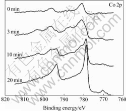
Fig.14 XP spectra of Co 2p region on Co-Ce with different sputtering times
3.2.3 XRD measurements
The Ni electrodes on Co-Ce modified substrates were prepared for the SOC and SOD sample after formation to analysis XRD patterns, and the results are shown in Fig.15 and Fig.16.
In Fig.15, the bare cobalt peaks, CoOOH and Co(OH)2 peaks appear. In Fig.16, the peaks of the CoOOH are predominant, which indicates that the film includes distinct CoOOH. YUAN et al[15] and FU et al[16] indicate that, the conductance value of CoOOH is 12.8 Ω-1?cm-1 but that of the NiOOH is 0.15 Ω-1?cm-1, and the value of CoOOH is 100 times more than that of NiOOH, 108 times more than that of Ni(OH)2. So we can conclude that the CoOOH on the substrate with electrodeposited Co-Ce modification can enhance the electron conductivity on the interface between substrate and active materials, and improve the charge-discharge performance of Ni electrode at high rate.
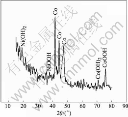
Fig.15 XRD pattern of electrodeposited Co-Ce at SOD
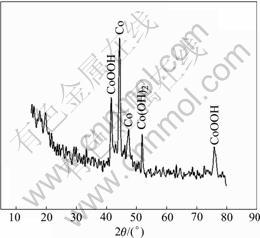
Fig.16 XRD pattern of electrodeposited Co-Ce at SOC
According to the mechanism of CoO dissolve- deposition in the active materials of Ni electrode[17], through dissolve-deposition process on the deposited Co-Ce substrate, CoOOH can be separated from the surface of sphere Ni(OH)2 which contacts on the substrate. The surface of substrate and sphere Ni(OH)2 is the same as CoOOH, which increases combining intensity between substrate and active materials and decrease the contacting resistance of interface between surface and active materials, furthermore improving nickel electrode charging and discharging performance.
4 Conclusions
1) The spicular grains on the nickel electrode substrate with electrodeposited Co-Ce alloys increase the contacting area between substrate and active materials, and the active materials can not break off easily.
2) After Ni electrode formation, the film is formed on the substrate surface with electrodeposited Co-Ce, and the depth is about 30 nm, containing the CoOOH and Co(OH)2.
3) The CoOOH on the electrodeposited Co-Ce substrate increases combining intensity between substrate and active materials, enhance electron conductivity, and improve electricity transmission ability and high rate charging or discharging ability.
References
[1] PYUN S I, KIM K H, HAN J N. Analysis of stresses generated during hydrogen extraction from and injection into Ni(OH)2 /NiOOH film electrode[J]. J Power Sources, 2000, 91(2): 92-98.
[2] CHEN H, WANG J M, PAN T, PAN T, XIAO H M, ZHANG J Q, CAO C N. Effect of high-energy ball milling (HEBM) on the structure and electrochemical performance of nickel hydroxide[J]. Int J Hydrogen Energy, 2003, 28 (1): 119-124.
[3] PRALONG V, DELAHAYE-VIDAL A, BEAUDOIN B, LERICHE J B, TARASCON J M. Electrochemical behavior of cobalt hydroxide used as additive in the nickel hydroxide electrode[J]. J Electrochem Soc, 2000, 147 (4): 1306-1313.
[4] Zimmerman A H. Technological implications in studies of nickel electrode performance and degradation[J]. J Power Sources, 1984, 12(3): 233-245.
[5] WANG F, WU F. Effects of iron phthalocyanine on performance of MH/Ni battery[J]. Trans Nonferrous Met Soc China, 2004, 14(2): 227-231.
[6] CHEN Hui, WANG Jian-ming, PAN Tao, XIAO Hui-ming, ZHANG Jian-qing. Structure and electrochemical performance of Al and Zn substituted α-Ni(OH)2[J]. The Chinese Journal of Nonferrous Metals, 2003, 13(1): 85-90. (in Chinese)
[7] ZHANG Q, XU Y H, WANG X L, HE G R. Effect of preparation conditions on properties of Al-substituted α-Ni(OH)2 prepared by homogeneous precipitation[J]. Trans Nonferrous Met Soc China, 2005, 15(3): 653-660.
[8] PRALONG V, DELAHAYE-VIDAL A, CHABRE Y, BEAUDOIN B, TARASCON J M. The outcome of cobalt in the nickel-cobalt oxyhydroxide electrodes of alkaline batteries[J]. J. Journal of Solid State Chemistry, 2001, 162(7): 270-281.
[9] LI L, WU F, YAN G K. Degradation analysis of nickel/metal hydride battery and its electrodes materials[J]. Trans Nonferrous Met Soc China, 2004, 14(3): 446-450.
[10] CHANG Zhao-rong, REN Xing-tao, PENG Peng, LI Bao. The effect of Ce on the properties of nickel hydroxide electrode[J]. J Functional Materials, 2002, 33(3): 291-293. (in Chinese)
[11] PRALONG V, DELAHAYE-VIDAL A, BEAUDOIN B, LERICHE J B, SCOYER J, TARASCON J M. Bismuth-enhanced electrochemical stability of cobalt hydroxide used as an additive in Ni/Cd and Ni/Metal hydride batteries[J]. J Electrochemical Soc, 2000, 147(6): 2096-2103.
[12] WANG D L, DAI C S, JIANG Z H. Performance of nickel electrode using Co-Ce alloy electrodeposited nickel foam[J]. J Battery Bimonthly, 2005, 35(2): 111-112.
[13] PENG Mei-xun, WANG Ling-sen, SHEN Xiao-qian, WEI Ya-hui, HE Wan-ning. Microstructures and formation mechanism of spherical β-Ni(OH)2[J]. The Chinese Journal of Nonferrous Metals, 2003, 13 (5): 1130-1135. (in Chinese)
[14] FOELSKE A, STREHBLOW H H. Structure and composition of electrochemically prepared oxide layers on Co in alkaline solutions studied by XPS[J]. J Surf Interface Anal, 2002, 34(1): 125-129.
[15] YUAN A B, XU N X. Electrochemical studies of the nickel electrode with cobalt modification [J]. J Appl Electrochem, 2001, 31(2): 245-250.
[16] FU Zhong-zhen, JIANG Wen-quan, YU Li-min. Preparation of nickel hydroxide coated by cobalt hydroxide[J]. The Chinese Journal of Nonferrous Metals, 2005, 15(11): 175-179. (in Chinese)
[17] OSHITANI M, YUFU H, TABASHLMA K. Development of a pasted nickel electrode with high active material utilization [J]. J Electrochemical Soc, 1989,136(6): 1590-1593.
Corresponding author: WANG Dian-long; Tel: +86-451-86413751; E-mail: dlwang@hit.edu.cn
(Edited by YANG Bing)

